Vega VEGAPOINT 31 Operating Instructions Manual
Capacitive level switch, transistor with io-link
Hide thumbs
Also See for VEGAPOINT 31:
- Operating instructions manual (52 pages) ,
- Operating instructions manual (56 pages)

Related Manuals for Vega VEGAPOINT 31


Summary of Contents for Vega VEGAPOINT 31
- Page 1 Operating Instructions Capacitive level switch VEGAPOINT 31 Transistor with IO-Link Document ID: 62325...
-
Page 2: Table Of Contents
Connecting ........................29 Sensor parameter adjustment ..................30 Setup with PC/notebook (Bluetooth) ................... 31 Preparations ........................31 Connecting ........................31 Sensor parameter adjustment ..................32 10 Diagnostics and servicing ....................33 10.1 Maintenance ........................33 VEGAPOINT 31 • Transistor with IO-Link... - Page 3 13.1 Technical data ........................ 39 13.2 Device communication IO-Link ..................42 13.3 Maße ..........................48 13.4 Industrial property rights ....................50 13.5 Licensing information for open source software ............. 50 13.6 Trademark ........................50 Editing status: 2021-02-08 VEGAPOINT 31 • Transistor with IO-Link...
-
Page 4: About This Document
Symbols used Document ID This symbol on the front page of this instruction refers to the Docu- ment ID. By entering the Document ID on www.vega.com you will reach the document download. Information, note, tip: This symbol indicates helpful additional infor- mation and tips for successful work. -
Page 5: For Your Safety
During work on and with the device, the required personal protective equipment must always be worn. Appropriate use The VEGAPOINT 31 is a sensor for point level detection. You can find detailed information about the area of application in chapter " Product description". Operational reliability is ensured only if the instrument is properly used according to the specifications in the operating instructions manual as well as possible supplementary instructions. -
Page 6: Safety Instructions For Ex Areas
USA and Canada. Safety instructions for Ex areas For Ex applications, only devices with corresponding Ex approval may be used. Observe the Ex-specific safety instructions. These are an integral part of the operating instructions and are enclosed with every device with Ex approval. VEGAPOINT 31 • Transistor with IO-Link... -
Page 7: Product Description
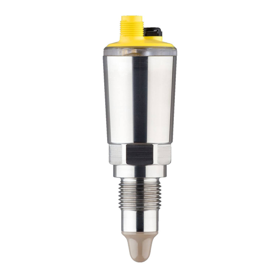
This operating instructions manual applies to the following instrument instructions versions: • Hardware version from 1.0.0 • Software version from 1.3.0 Constituent parts The VEGAPOINT 31 consists of the components: • Housing with integrated electronics • Process fitting • Plug (optional) Fig. 1: VEGAPOINT 31... -
Page 8: Principle Of Operation
Alternatively, you can find all via your smartphone: • Scan the QR-code on the type label of the device or • Enter serial number manually in the VEGA Tools app (available free of charge in the respective stores) Principle of operation Anwendungsbereich Der VEGAPOINT 31 ist ein kapazitiver Grenzstandsensor zur Grenz- standerfassung. -
Page 9: Adjustment
Buildup is ignored to a certain degree and therefore has no influence on the measurement. Adjustment Local adjustment The switching status of VEGAPOINT 31 can be checked from outside (LED illuminated ring). Note: The LED illuminated ring is not available for device versions with full metal housing. -
Page 10: Packaging, Transport And Storage
Unless otherwise indicated, the packages must be stored only under the following conditions: • Not in the open • Dry and dust free • Not exposed to corrosive media • Protected against solar radiation • Avoiding mechanical shock and vibration VEGAPOINT 31 • Transistor with IO-Link... -
Page 11: Accessories
The instructions for the listed accessories can be found in the down- load area on our homepage. Threaded and hygienic Various threaded and hygienic sockets are available for devices with socket threaded version. You can find further information in the "Technical data" Schutzhaube Bei Geräten mit Staub-Ex-Zulassung muss das Gehäuse vor äußerer Beschädigung geschützt werden. Verwenden Sie dazu die optionale Schutzhaube. VEGAPOINT 31 • Transistor with IO-Link... -
Page 12: Mounting
• Chemical properties of the medium • Abrasion and mechanical influences Schaltpunkt Der VEGAPOINT 31 kann in jeder beliebigen Lage eingebaut werden. Das Gerät muss lediglich so montiert werden, dass sich der Sensor auf Höhe des gewünschten Schaltpunktes befindet. Fig. 4: Einbaubeispiele Obere Füllstandsdetektion (max.) als Überlaufschutz Untere Füllstandsdetektion (min.) als Trockenlaufschutz Trockenlaufschutz (min.) für eine Pumpe... -
Page 13: Mounting Instructions
Gerät und führen Sie das Kabel seitlich oder nach oben durch die Schutzhaube. Setzen Sie die Schutzhaube gemäß folgender Abbildung um das Gerätegehäuse und befestigen Sie die beiden Hälften mit den beilieg- enden Schrauben (1 Nm/0.74 lb ft). VEGAPOINT 31 • Transistor with IO-Link... - Page 14 4 Mounting Fig. 5: Montage der Schutzhaube Schutzhaube - 1. Hälfte Schutzhaube - 2. Hälfte Befestigungsschrauben (2 Stück) VEGAPOINT 31 VEGAPOINT 31 • Transistor with IO-Link...
-
Page 15: Connecting To Power Supply
EN 61326-1 for industrial areas, shielded cable should be used. Connecting Instrument versions Fig. 6: Instrument versions Device version with housing 316L and plastic Device version with full metal housing 316L 360° status indication VEGAPOINT 31 • Transistor with IO-Link... -
Page 16: Wiring Plan
Contact, plug connector Function/Polarity Voltage supply/+ Transistor output 2 Voltage supply/- Transistor output 1/IO-Link Switch-on phase After switching on, the device first carries out a self-test in which the function of the electronics is checked. The current measured value is then output on the signal cable. VEGAPOINT 31 • Transistor with IO-Link... -
Page 17: Access Protection
If this document is lost, the emergency device code can be retrieved from your personal contact person after legitimation. The storage and transmission of the device codes is always encrypt- ed (SHA 256 algorithm). VEGAPOINT 31 • Transistor with IO-Link... -
Page 18: Storing The Codes In Myvega
" PINs and Codes". This greatly simplifies the use of additional adjust- ment tools, as all Bluetooth access and device codes are automati- cally synchronized when connected to the " myVEGA" account VEGAPOINT 31 • Transistor with IO-Link... -
Page 19: Setup
There are several ways to operate the device. The Bluetooth version (optional) of the instrument enables a wireless connection to standard adjustment units. This can be smartphones/ Default setting Default setting Default setting Output 1 VEGAPOINT 31 • Transistor with IO-Link... - Page 20 0,5 s Schaltausgang 2 Schaltpunkt (SP2) 85 % Schaltverzögerung (DS2) 0,5 s Rückschaltpunkt (RP2) 83 % Rückschaltverzögerung (DR2) 0,5 s Anzeige Helligkeit LED-Leuchtring 100 % Signalisierung NAMUR NE 107 Störung Schaltausgang Gelb Betriebszustand Grün Only for "User-defined" application VEGAPOINT 31 • Transistor with IO-Link...
-
Page 21: Parameter Adjustment
• User-defined Note: The selection of the application has a considerable influence on all other menu items. Keep in mind that as you continue with the param- eter adjustment, individual menu items are only optionally available. Standard (level detection) • Uncovered Only DTM adjustment VEGAPOINT 31 • Transistor with IO-Link... - Page 22 Only when the reset point (RP) is reached does the output switch back. If the measured variable moves between switching and reset point, the state of the output does not change. VEGAPOINT 31 • Transistor with IO-Link...
- Page 23 Window High (FH) and Window Low (FL). If the measured variable leaves the window, the output returns to its previous state. If the measured variable moves within the window, the state of the output does not change. VEGAPOINT 31 • Transistor with IO-Link...
- Page 24 The setting is a degree for the sensitivity of the sensor tip. Switching delay (DS1) The switching delay (DS) extends the reaction time until the sensor is switched over when the sensor tip is covered. VEGAPOINT 31 • Transistor with IO-Link...
- Page 25 • Failure/malfunction - Red • Operating status/output 1 closed - Yellow • Operating status/output 1 open - Green In addition there are the following status indications: • Simulation - red flashing • Maintenance required - green flashing VEGAPOINT 31 • Transistor with IO-Link...
- Page 26 Units In this menu item you can define the temperature unit of the device (UNI). • °C • °F 7.4.3 Diagnostics Status In this menu item you can retrieve the status of the device. • Device status • Status outputs VEGAPOINT 31 • Transistor with IO-Link...
- Page 27 In this menu item you can simulate the function of the two switching outputs separately. Note: Make sure the connected downstream devices are activated during the simulation. First select the desired switching output and start the simulation. Then select the desired switching state. VEGAPOINT 31 • Transistor with IO-Link...
- Page 28 Hardware version • Software version • Factory calibration date • Device Revision Sensor characteristics In this menu item you can retrieve the sensor features of the device. • Order texts • Instrument version • Electronics VEGAPOINT 31 • Transistor with IO-Link...
-
Page 29: Setup With Smartphone/Tablet (Bluetooth)
• Operating system: Android 5.1 or newer • Bluetooth 4.0 LE or newer Download the VEGA Tools app from the " Apple App Store", " Goog- le Play Store" or " Baidu Store" to your smartphone or tablet. Connecting Connecting Start the adjustment app and select the function "... -
Page 30: Sensor Parameter Adjustment
The sensor adjustment menu is divided into two halves: On the left you'll find the navigation section with the menus " Setup", " Diagnosis" and others. The selected menu item, recognisable by the colour change, is dis- played in the right half. Fig. 11: Example of an app view - Setup VEGAPOINT 31 • Transistor with IO-Link... -
Page 31: Setup With Pc/Notebook (Bluetooth)
Enter Bluetooth access For authentication, enter in the next menu window the 6-digit code Bluetooth access code: Fig. 12: Enter Bluetooth access code VEGAPOINT 31 • Transistor with IO-Link... -
Page 32: Sensor Parameter Adjustment
The sensor adjustment menu is divided into two halves: On the left you'll find the navigation section with the menus " Setup", " Display", " Diagnosis" and others. The selected menu item, recognisable by the colour change, is dis- played in the right half. Fig. 13: Example of a DTM view - Setup VEGAPOINT 31 • Transistor with IO-Link... -
Page 33: Diagnostics And Servicing
24 hour service hotline Should these measures not be successful, please call in urgent cases the VEGA service hotline under the phone no. +49 1805 858550. The hotline is also available outside normal working hours, seven days a week around the clock. -
Page 34: Diagnosis, Fault Messages
Function check - orange Maintenance required - blue Failure: Due to a malfunction in the instrument, a fault message is output. This status message is always active. It cannot be deactivated by the user. VEGAPOINT 31 • Transistor with IO-Link... - Page 35 Finish simulation Simulation active Wait for the automatic end after 60 mins. Out of specification Code Cause Rectification Text message S600 Temperature of the electronics in the Check ambient temperature non-specified range Impermissible electronics Insulate electronics temperature VEGAPOINT 31 • Transistor with IO-Link...
-
Page 36: Software Update
Clean the instrument and pack it damage-proof • Attach the completed form and, if need be, also a safety data sheet outside on the packaging • Ask the agency serving you to get the address for the return ship- ment. You can find the agency on our homepage. VEGAPOINT 31 • Transistor with IO-Link... -
Page 37: Dismount
11.2 Disposal The device is made of recyclable materials. For this reason, it should be disposed of by a specialist recycling company. Observe the ap- plicable national regulations. VEGAPOINT 31 • Transistor with IO-Link... -
Page 38: Certificates And Approvals
That is why we have introduced an environment management system with the goal of continuously improving company environmental pro- tection. The environment management system is certified according to DIN EN ISO 14001. Please help us fulfil this obligation by observ- ing the environmental instructions in chapters " Packaging, transport and Lagestoragerung", " Disposal" of these operating instructions. VEGAPOINT 31 • Transistor with IO-Link... -
Page 39: Supplement
Ʋ Thread G1, 1 NPT 100 Nm (73 lbf ft) Ʋ Hygienic adapter 20 Nm (15 lbf ft) Surface quality < 0.76 µm (3.00 Measurement accuracy Hysteresis approx. 1 mm (0.04 in) nicht medienberührt VEGAPOINT 31 • Transistor with IO-Link... - Page 40 Output variable - Transistor output/IO-Link Output signal Transistor output NPN/PNP Output signal IO-Link acc. to IEC 61131-9 Connection technology Three-wire Load current max. 250 mA Overload resistance Short-circuit resistance Permanently Switching voltage < 34 V DC VEGAPOINT 31 • Transistor with IO-Link...
- Page 41 IP66/IP68 (0.2 bar)/IP69 NEMA 6P Altitude above sea level up to 5000 m (16404 ft) Overvoltage category Protection class Pollution degree Depending on the local conditions; with M12 x 1 plug stainless steel (closed full metal housing) effective range up to approx. 5 m (16.40 ft) Depending on the instrument version VEGAPOINT 31 • Transistor with IO-Link...
-
Page 42: Device Communication Io-Link
0 (LSB) Sensor X-value 0.1 % (frequency) Temperature in °C, resolution 0.1 K Out2 Out1 Formats Value Type Out1 1 Bit Boolean Out2 1 Bit Boolean Temperature 14 Bit Integer X-value 16 Bit Integer VEGAPOINT 31 • Transistor with IO-Link... - Page 43 Software Re- 0x0017 String vision Application 0x0018 Max. 31 String Sensor Specific Tag FunctionTag 0x0019 Max. 31 String LocationTag 0x001A Max. 31 String Device Status 36 0x0024 unsigned8[2] Detailed De- 0x0025 unsigned8[12] RO vice Status VEGAPOINT 31 • Transistor with IO-Link...
- Page 44 0 = HNO, 1=HNC 2 = FNO, 3=FNC Brightness illuminated ring 0x0115 Unsigned8 0 … 100% (LED) in 10 % steps Signalling 0x0116 Unsigned8 0 = Individual sig- nalling 1 = acc. to NA- MUR NE 107 VEGAPOINT 31 • Transistor with IO-Link...
- Page 45 Individual Signal- ling - switching output Temperature unit (TMP) 0x0123 Float 1001 = °C 1002 = °F Bluetooth access code 0x0124 String (BT) Protection of parameter 0x0125 Unsigned8 0 = deactivated adjustment 1= activated VEGAPOINT 31 • Transistor with IO-Link...
- Page 46 1 = Closed Output 2 0x0135 Unsigned16 RO 0 = Open 1 = Closed Device name 0x0136 String Serial number 0x0137 String Hardware version 0x0138 String Software version 0x0139 String Device revision 0x013A Unsigned16 RO VEGAPOINT 31 • Transistor with IO-Link...
- Page 47 ISDU (hex) Access Factory Reset 0x082 Reset Pointer - Resonance Frequency 0x0A1 Reset Pointer - Measuring Cell Temperature 0x0A3 Reset Pointer - Electronic Temperature 0x0A4 Uncovered 0x0A5 Covered 0x0A6 Accepting and activating taught-in settings 0x0AC VEGAPOINT 31 • Transistor with IO-Link...
-
Page 48: Maße
ø 18 mm (0.71") (0.71") Fig. 15: VEGAPOINT 31, Standardausführung - Gewinde mit M12 x 1-Stecker Gewinde G½, G¾, G1 (DIN ISO 228/1) mit M12 x 1-Steckeranschluss Gewinde G½, G¾, G1 (DIN ISO 228/1) mit M12 x 1-Steckeranschlusss - Vollmetallausführung Gewinde ½... - Page 49 13 Supplement VEGAPOINT 31, Schutzhaube ø 46 mm (1.81") Fig. 17: VEGAPOINT 31, Schutzhaube VEGAPOINT 31 • Transistor with IO-Link...
-
Page 50: Industrial Property Rights
Les lignes de produits VEGA sont globalement protégées par des droits de propriété intellec- tuelle. Pour plus d'informations, on pourra se référer au site www.vega.com. VEGA lineas de productos están protegidas por los derechos en el campo de la propiedad indus- trial. Para mayor información revise la pagina web www.vega.com. - Page 51 Notes VEGAPOINT 31 • Transistor with IO-Link...
- Page 52 Subject to change without prior notice © VEGA Grieshaber KG, Schiltach/Germany 2021 VEGA Grieshaber KG Am Hohenstein 113 Phone +49 7836 50-0 77761 Schiltach E-mail: info.de@vega.com...
Need help?
Do you have a question about the VEGAPOINT 31 and is the answer not in the manual?
Questions and answers