
Subscribe to Our Youtube Channel
Related Manuals for AOR ARD9800


Summary of Contents for AOR ARD9800
- Page 1 ® ARD9800 FAST RADIO MODEM Multi-Mode and Digital Voice Interface Operating manual AOR, LTD.
- Page 2 Thank you for purchasing the AOR ARD9800 Multimode And Digital Voice Interface. The ARD9800 is designed to convert your HF radio equipment to a multi mode and digital voice radio without performing any modifications to your transceiver. Please read through this instruction manual and familiarize yourself with the operation of the ARD9800.
- Page 3 (High frequency) bands at no extra cost. (Speed may be limited by regulations in certain jurisdictions.) Small and compact unit. Easy to operate. Simply connect the ARD9800 to the microphone jack. No complicated or risky radio modifications are necessary. Utilizes a uniquely designed high performance DSP (Digital Signal Processor) engine.
- Page 4 Precautions To prevent fire, personal injury, or unit damage, please observe the following precautions: Do not attempt to adjust this unit unless instructed to do so by this manual. Do not expose the unit to direct sunlight or place the unit close to heating appliances. Do not place the unit in excessively dusty, humid or wet areas.
-
Page 5: Table Of Contents
Top Panel ----------------------------------------------------------------------- 10 Internal View ------------------------------------------------------------------ 10 Bottom View ------------------------------------------------------------------ 11 Interfacing the ARD9800 ------------------------------------------------------ 12 Connection to a Radio ----------------------------------------------------- 12 Connection to a Microphone -------------------------------------------- 13 Connection to a PC -------------------------------------------------------- 13 Connection to a Power supply ----------------------------------------- 13... -
Page 6: Supplied Accessories
Supplied Accessories The following items are provided in the box: Accessory Quantity Microphone PC interface cable Speaker Cable DC Power cable 8P metal plug (for radio cable) Instruction manual... -
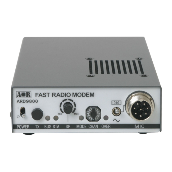
Page 7: Controls And Functions
Controls and Functions Front Panel 1 1 1 1 0 0 0 0 1 1 1 1 0 0 0 0 1 1 1 1 | ○ M M M M I I I I C C C C P P P P O O O O W W W W E E E E R R R R T T T T X X X X B B B B U U U U S S S S S S S S T T T T A A A A... - Page 8 Select the Digital voice mode (10101) or the Analog voice mode (~) When the Analog voice mode (~) is selected, ordinary analog voice communications will be made. In the receive mode, however, the ARD9800 will automatically detect the mode of the incoming signal and decode signals accordingly. The LED indicates the appropriate operation mode.
-
Page 9: Rear Panel
Microphone signal input Rear Panel AOR,LTD. VIDEO DC IN RADIO k. Communication Connector (mini DIN 8 pin) A communication connector for PC (RS-232C) Pin Number Signal Signal Direction ARD9800----->PC ARD9800----->PC ARD9800<-----PC ARD9800<-----PC ARD9800----->PC ARD9800<-----PC No Connection Shell Frame ground Baud Rate: 9600bps... - Page 10 No connection Ground No connection Note: MIC GND and GND must not be connected together in the ARD9800 connector, or RF feedback will result. o. SP IN Connector (3.5 mm mono jack) Connect to the radio equipment’s speaker jack. (Input level: 0.5 V – 5 V p-p) Note: Output signal from the accessory connector of the radio may not be high enough to use for this purpose.
-
Page 11: Top Panel
5.6 ~ 6.5 VDC. DO NOT apply 12.0 V or severe damage will result, and the warranty will be void! Note: There is no low battery voltage detector built-into the ARD9800. r. FG Screw... -
Page 12: Bottom View
5.6 ~ 6.5 VDC. DO NOT apply 12.0V or severe damage will result, and the warranty will be void! Note: There is no low battery voltage detector built-into the ARD9800. w. Internal speaker setting Jumper setting 1 –... -
Page 13: Interfacing The Ard9800
Interfacing the ARD9800 Connection to a Radio Before using your ARD9800, you will first need to wire the cable between your radio equipment and the ARD9800. For your convenience, an 8-pin of a microphone connector for the ARD9800 is included. -
Page 14: Connection To A Microphone
Connection to a Microphone A speaker microphone is included with your ARD9800. However, if you wish to use your own microphone with the ARD9800, you may do so by wiring your microphone to the ARD9800. Below are the pin assignments of the microphone connector of the ARD9800. -
Page 15: Connection To An External Speaker
5.6 ~ 6.5 VDC. DO NOT apply 12.0 V or severe damage will result, and the warranty will be void! Note: There is no low battery voltage detector built-into the ARD9800. Connection to an External Speaker If an external speaker is desired, connect it to the SP OUT jack. -
Page 16: Presetting
If the ALC function activates too much, it might create audio distortion. As a result, the communication with a distant station might be compromised. 6. Adjust the output level located on the bottom side of the ARD9800 when the microphone gain control on the radio transceiver does not adjust for sufficient level. -
Page 17: Microphone Level
Therefore, no further adjustment is needed for normal operation. If you wish to use your own microphone, you will need to wire your microphone connector to match the pins of the ARD9800, and then adjust the microphone level as described in the following steps: 1. -
Page 18: User Id Setting
User ID Setting The ARD9800 provides a function of user ID that allows assigning an own identifying number. In operation with digital mode, you can assign the ID number for the specified destination’s station along with NETMASK (Group Code) and SQUELCH (DCS) functions together. - Page 19 Communication pattern Tx 1 Rx 1 ID:12345 UID:12345 NM:FFF00 MD:1 MD:1 Rx 2 ID:12345 UID:12355 NM:FFFF0 MD:1 MD:1 ID:12345 UID:12348 NM:FFFFF MD:1 MD:1 ID:12345 UID:13345 NM:FFFFF MD:1 MD:0 UID:12345 MD:0 Note: All adjustments must be properly performed before operation.
-
Page 20: Operation
Press and hold the PTT switch of the microphone, and speak into the microphone normally. Data Communication Run a terminal software program to control the ARD9800, and to enter control commands. Refer to Control Commands at page 22 for details Two different types of data, ASCII data or binary data, can be used. -
Page 21: Digital Image Communication
(like noise). Transmit Push the TX switch to send the image. (When pin - 4 of the microphone connector is grounded, the ARD9800 starts sending the image.) Note: When the Video Through Function is activated (AVT command is ON=... -
Page 22: Specifications
Digital voice mode: Manual select by the mode switch Digital Image mode: Manual select by pressing the TX switch Analog voice mode: Manual select by the mode switch Video AOR original JPEG format Compression Video NTSC or PAL depending on version... -
Page 23: Control Commands
NOTE: Make sure that your PC’s serial port is active. Check for correct hardware and software settings! Below are the pin assignments of the COM connector of the ARD9800. ARD9800 COM connector Serial connector to the PC (D-Sub 9 – pin) - Page 24 CCC: Command (Must be a capital letter) Space Parameter [CR]: Carriage Return Entering a command without a parameter will display the current parameter (value) setting. cmd>CCC[CR] If an invalid parameter or command is entered, the ARD9800 will respond as follows: cmd> cmd>...
-
Page 25: Command List
Command List Comman Function Send VIDEO In signal to VIDEO OUT (to a monitor screen) Capture image into memory of the ARD9800 Enter the Converse mode TX channel settings List the current commands Display current settings Activate AFC (Automatic Frequency control) function... - Page 26 AAQ {0 / 1} [CR] Parameter 1: Send VIDEO In signal to a VIDEO OUT (to the monitor screen) 0: Capture image into memory of the ARD9800 Details While AVT command is OFF, [AAQ 0] will be accepted. Entering AAQ[CR] will respond with the current status.
- Page 27 NM----- NetMask MD----- Digital Squelch Details The ARD9800 provides a function of user ID that allows assigning an own identified number. In operation with digital mode, you can assign the ID number for the specified destination’s station along with NETMASK (Group Code) and SQUELCH (DCS) functions together.
- Page 28 Function Display current settings Default Headerlen : 1.00 AFC = ON Analog : ON Format ADS [CR] Parameter None Details Displays the current parameter settings Example ADS [CR] Function Activate AFC (Automatic Frequency control) function Default Format AFC {ON/OFF} [CR] Parameter ON: Activates the AFC function OFF: Deactivates the AFC function...
- Page 29 Function Monitor both digital/analog voice signals or monitor digital voice only Default Format ARA_ {ON/OFF} [CR] Parameter ON : Monitor digital voice and Analog voice OFF : Monitor Digital voice only Details Monitor both digital/analog voice signal or monitor digital voice only Example ARA_ON [CR]...
- Page 30 Function Display the current firmware version Default None Format AVR [CR] Parameter None Details Displays the current firmware version Example AVR [CR]...
- Page 31 Manufacturer: AOR, LTD. 2-6-4, Misuji, Taito-Ku, Tokyo, 111-0055, Japan URL: www.aorja.com US distributor: AOR USA, INC. 20655 S. Western Ave. Suite 112 Torrance, CA 90501 Phone: 310-787-8615 Fax: 310-787-8619 URL: www.aorusa.com e-mail: info@aorusa.com April 17, 2013 Printed in Japan...
Need help?
Do you have a question about the ARD9800 and is the answer not in the manual?
Questions and answers