Table of Contents
Advertisement
Quick Links
Advertisement
Table of Contents

Related Manuals for AOR ARD9800


Summary of Contents for AOR ARD9800
- Page 1 Discover the Power of Communications ™ http://www.ameradio.com TO ORDER – VISIT FAST RADIO MODEM ARD9800 ARD9800 ARD9800 ARD9800 I n s t r u c t i o n M a n u a l Multi-Mode And Digital Voice Interface AOR, LTD.
- Page 2 Thank you for purchasing the AOR ARD9800 Multimode and Digital Voice Interface. The ARD9800 is designed to convert your HF radio equipment to a multi mode and digital voice capable radio without performing any modifications to your transceiver. Please read through this instruction manual and familiarize yourself with the operation of the ARD9800.
- Page 3 Digital voice communications using existing analog 2 way radios. The ARD9800 uses the same audio frequencies (300 Hz ~ 2500 Hz) as microphone audio to modulate the voice signal. This allows you to use an analog radio as a digital voice transceiver.
- Page 4 Information to the Digital Device user required by the FCC This equipment has been tested and found to comply with the limits for a Class B digital device, pursuant to Part 15 of the FCC Rules. These limits are designed to provide reasonable protection against harmful interference in a residential installation.
-
Page 5: Table Of Contents
Front Panel ------------------------------------------------------------------- Rear Panel -------------------------------------------------------------------- T op Panel ----------------------------------------------------------------------- Internal View ------------------------------------------------------------------ Bottom View ------------------------------------------------------------------ Interfacing the ARD9800 ------------------------------------------------------ Connection to a Radio ----------------------------------------------------- Connection to a Microphone -------------------------------------------- Connection to a PC -------------------------------------------------------- Connection to a Power supply -----------------------------------------... -
Page 6: Supplied Accessories
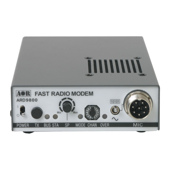
Supplied Accessories The following items are provided in the box: Accessory Quantity ---------------------------------------------------------------- Microphone PC interface cable Speaker Cable DC Power cable Microphone Connector Instruction manual (this booklet) Controls and functions Front Panel 1 1 1 1 0 0 0 0 1 1 1 1 0 0 0 0 1 1 1 1 |... - Page 7 switch will enable output of the video signal connected to the Video Input to also be sent to the video output port, so that you can monitor the video image. Press this switch again to capture and send the image through the radio equipment. When the Video Through Function is de-activated (AVT command is OFF), pressing this switch will automatically capture the video image and then transmit it through the radio equipment.
- Page 8 After the adjustment is completed, push the TX switch to save the new setting. The STALED will light to indicate the setting process is completed. T o complete the operation, turn the power of the ARD9800 off, and turn back it on. h. Overload indicator Lit when the microphone input is overloaded (too high).
-
Page 9: Rear Panel
When this pin is left open, the operation mode will be set by the mode switch on the front panel. MIC PTT -- PTT (Push T o T alk) input. MIC GND -- Microphone ground signal MIC IN -- Microphone signal input Rear Panel AOR,LTD. VIDEO ‑ DC IN RADIO... - Page 10 Connect a video monitor to this connector to monitor a received image or a picture to be sent. RADIO Connector Using the supplied 8 pin connector, connect the ARD9800 to your radio equipment. Y ou will need to wire a cable according to the microphone connector specifications of your radio.
- Page 11 No connection Ground No connection Note: MIC GND and GND must not be connected together in the ARD9800 connector, or RF feedback will result. SP IN Connector (3.5 mm mono jack) Connect to the radio equipment’s speaker jack. (Input level: 0.5 V – 5 V p-p) Note: The output signal from a radio’s “accessory”...
- Page 12 If you have changed the internal jumper for low-voltage battery operation, battery voltage must be within the range of 5.6 ~6.5 VDC. DO NOT apply 12.0V or severe damage will result, and the warranty will be void! Note: No low battery voltage detector is built-in the ARD9800. Frame ground...
-
Page 13: Top Panel
Top Panel Internal Speaker Internal View Factory setting jumper Must be set between 2-3. (Do not change this setting at any time.) - Page 14 5.6 ~6.5 VDC. DO NOT apply 12.0V or severe damage will result, and the warranty will be void! Note: No low battery voltage detector is built-in the ARD9800. Internal speaker setting Jumper setting 1 –...
-
Page 15: Bottom View
Interfacing the ARD9800 Connection to a Radio Before using your ARD9800, you will first need to wire the cable between your radio equipment and the ARD9800. For your convenience, an 8-pin of a microphone connector for the ARD9800 is included. -
Page 16: Connection To A Radio
PTT (Push T o T alk) Output (H level) PTT (L) PTT (Push T o T alk) Output (Low level) No connection No connection Ground No connection Note: MIC GND and GND must not be connected together in the ARD9800 connector, or RF feedback will result. -
Page 17: Connection To A Microphone
A speaker microphone is included with your ARD9800. However, if you wish to use your own microphone with the ARD9800, you may do so by wiring your microphone to correlate with the input jack of the ARD9800. Below are the pin assignments of the Microphone connector of the ARD9800. -
Page 18: Connection To A Power Supply
If you wish to use your own microphone rather than the included one, you will need to wire your microphone connector to match the pins of the ARD9800, and then adjust the microphone level as described in the following steps:... -
Page 19: Radio Input Level
After the adjustment is completed, push the TX switch to save the new setting. The STA LED will light to indicate the setting process is completed. 5. T o complete the operation, turn the power of the ARD9800 off, and then turn back it on. -
Page 20: Operation
Voice Communication Y our ARD9800 is capable of Digital Voice Communications and Analog Voice Communication. In the receive mode, the ARD9800 will automatically recognize the type of communication, and set the appropriate operation mode. In the transmit mode, the operation mode can be selected by using the front Mode switch. -
Page 21: Transmit
Transmit Enter the command [ACO] to go into the converse mode. Type text from the keyboard, then hit the enter key at the end of the text. NNNNNNNN [CR] NNNNNNNN ASCII character [CR] Carriage Return Note: Maximum data length is 2046 bytes per packet. T o send binary data, add [FE] (hexadecimal) to a header and footer with the data. -
Page 22: Digital Image Communication
If received data is missing during a transmission, that portion will be displayed as invalid (like noise). Transmit When pin - 4 of the microphone connector is grounded, the ARD9800 starts sending the image. Note: When the Video Through Function is activated (AVT command is ON), pressing the TX switch will enable output of the video signal connected to the Video Input to also be sent to the video output, so that you can monitor the video image. -
Page 23: Specifications
Digital voice mode: Manually selected by the mode switch Digital Image mode: Manually selected by pressing the TX switch Analog voice mode: Manually selected by the mode switch Video Compression AOR original JPEG format Video Input/output NTSC (NTSC 1Vp-p 75ohm) Power Requirement 10.7 ~ 16 V DC (Approximately 200 mA @ 12 V DC) -
Page 24: Control Commands
[10101] ) to the serial port of a PC. NOTE: Be sure your PC’s serial port is active. Check for correct hardware and software settings! Below are the pin assignments of the COM connector of the ARD9800. ARD9800 COM connector Serial connector of a PC (D-Sub 9 –... - Page 25 Command Format Run a terminal software program, and then turn the power of the ARD9800 on. The following message should appear on the PC screen: cmd> This indicates the ARD9800 is ready to accept commands from the PC. Each command consists of three (3) alphabetical characters.
- Page 26 Command List Command Function Send VIDEO In signal to VIDEO OUT (to a monitor screen) Capture image into memory of the ARD9800 Enter the Converse mode List the current commands Display current settings Activate AFC (Automatic Frequency control) function Set the duration of the synchronization header...
- Page 27 AAQ {0 / 1} [CR] Parameter 1: Send VIDEO In signal to a VIDEO OUT (to the monitor screen) 0: Capture image into memory of the ARD9800 Details While AVT command is OFF, [AAQ 0] will be accepted. Entering AAQ[CR] will respond with the current status.
- Page 28 Function List the current commands Default None Format ADC [CR] Parameter None Details Lists the current commands Example ADC [CR] Function Display current settings Default Headerlen : 1.00 AFC = ON Analog : ON Format ADS [CR] Parameter None Details Displays the current parameter settings Example ADS [CR]...
- Page 29 Function Set the duration of the synchronization header Default 100 (1 second) Format AHL {050 – 198} [CR] Parameter 050 – 198 (0.02 incremental) Details Sets the duration of the synchronization header {100} represents 1.00 second . Example AFC_146 [CR] Set duration to 1.46 seconds.
- Page 30 Function Selects the output level to the radio equipment Default Format ATT_ {ON/OFF} [CR] Parameter ON : Lower level OFF : Higher level Details Selects the output level to the radio equipment Refer to Level Adjustment at page XX for details Example ATT_ON [CR] Function...
- Page 31 Function Display the current firmware version Default None Format AVR [CR] Parameter None Details Displays the current firmware version Example AVR [CR]...
-
Page 32: Limited Warranty
AOR USA, Inc. (AOR) warrants its products as described below: AOR will repair or exchange equipment as a result of defects in parts or workmanship for a period of one year from the date of original retail purchase from an authorized AOR dealer. - Page 33 (310) 787-8615 during normal business hours (9 am ~ 5 pm Pacific Time Zone), or write to AOR, 20655 S. Western Ave., Suite 112, T orrance, CA 90501. Y ou may also send a fax to AOR at (310) 787-8619. Additional information is available at the AOR web site: www.aorusa.com...
- Page 34 AOR, LTD. 2-6-4, Misuji, T aitok-Ku T okyo, 111-0055, Japan http://www.aorja.com AOR USA, INC. 20655 S. Western Ave. Suite 112 T orrance, CA 90501, U.S.A. Phone: 310-787-8615 Fax: 310-787-8619 http://www.aorusa.com info@aorusa.com Copyright © 2003 All rights reserved Rev. 1. 2...
Need help?
Do you have a question about the ARD9800 and is the answer not in the manual?
Questions and answers