
Related Manuals for Cameron NUFLO MC-III


Summary of Contents for Cameron NUFLO MC-III
- Page 1 NUFLO MC-III™ Panel Mount Flow Analyzer User Manual Manual No. 2350326-01, Rev. 02...
- Page 2 © 2013 Cameron International Corporation (“Cameron”). All information contained in this publication is confidential and proprietary property of Cameron. Any reproduction or use of these instructions, drawings, or photographs without the express written permission of an officer of Cameron is forbidden.
-
Page 3: Table Of Contents
MC-III™ Panel Mount Flow Analyzer Table of Contents Contents Important Safety Information ..........................ii Section 1—Introduction ........................... 7 Operation ................................7 Table 1.1—MC-III Panel Mount Specifications ..................... 8 LCD Display ............................... 10 Keypad ............................... 10 Interface Software ............................11 Power Supply ............................. 12 Multipoint Linearization .......................... - Page 4 Table of Contents MC-III™ Panel Mount Flow Analyzer Entering the Baud Rate ............................ 35 Section 4—Configuration and Operation via Software ................37 Installing the Software ............................37 Accessing Help ..............................37 Connecting to the Software ..........................38 Automating Functions on Software Startup ....................39 Changing Autorun Settings ........................
- Page 5 MC-III™ Panel Mount Flow Analyzer Table of Contents Section 5—Flow Logs and Event Logs ......................73 Auto-Save Log Formats............................ 74 Log Directory and Filenames..........................74 Flow Archive ..............................75 Downloading Flow Logs ..........................75 Viewing Trend Charts ..........................77 Printing/Saving a Report ..........................77 Viewing a Saved Report..........................
- Page 6 Table of Contents MC-III™ Panel Mount Flow Analyzer Slave Address (register 1009) ........................C-4 Baud Rate (register 1010) .........................C-4 Real Time ..............................C-5 Input Configuration ............................C-5 Output Configuration ..........................C-8 Holding Registers (16-bit Mode) .......................C-9 Base Units/Configured Units ........................C-11 Conversion Factors ..........................C-11 Polling Registers .............................C-11 Pointer/Daily/Event Pointer (registers 17001 through 17006) ..............C-11 Real Date (registers 17007, 17008) ......................C-11 Real Time (registers 17009, 17010) ......................C-12...
-
Page 7: Section 1-Introduction
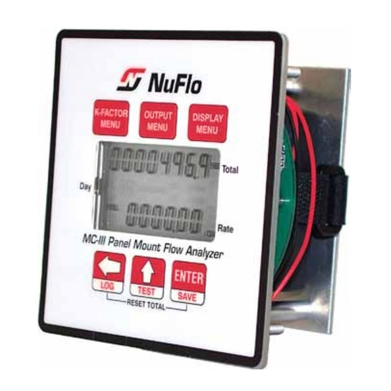
MC-III™ Panel Mount Flow Analyzer Section 1 Section 1—Introduction The NuFlo™ MC-III™ Panel Mount Flow Analyzer (Figure 1.1) packs a full spectrum of gas and liquid measurement functionality, high-speed performance, and log archive and retrieval capabilities in an easy- to-use totalizer. Commonly used operations can be accessed from the six-button keypad on the front of the instrument or from the dynamic interface software, allowing you to calibrate and configure the unit quickly and easily. - Page 8 Section 1 MC-III™ Panel Mount Flow Analyzer Table 1.1—MC-III Panel Mount Specifications System Power Internal power supply • 3.6 VDC, D-size lithium battery (2-year typical life) External power supply (6 to 30 VDC at 6 mA) with internal battery backup (reverse polarity protected) Loop-powered (4-20 mA) with internal battery backup (reverse polarity protected)
- Page 9 MC-III™ Panel Mount Flow Analyzer Section 1 Table 1.1—MC-III Panel Mount Specifications Outputs Analog Output 4-20 mA, loop-powered (two-wire) 16-bit resolution Accuracy: 0.1% of full scale @ 25°C, 50 PPM/°C temperature drift Loop power: 8.0 to 30 VDC Zero and full-scale engineering values configurable from front panel RS-485 Communications Baud rates: 300, 600, 1200, 2400, 4800, 9600, 19200, 38400, 57600 and up to 115.2K...
-
Page 10: Lcd Display
Section 1 MC-III™ Panel Mount Flow Analyzer • input options • output options • flow log archival • password-protected security LCD Display The liquid crystal display (Figure 1.2, page 11) provides a simultaneous indication of accumulated total (top readout) and flow rate (bottom readout). The eight-digit total display uses 7-segment characters to form numbers and letters, which results in a combination of uppercase and lowercase letters. -
Page 11: Interface Software
MC-III™ Panel Mount Flow Analyzer Section 1 00000000 Total X1000 STANDARD X1000 000000 /SEC /MIN Rate /DAY Figure 1.2—LCD display showing location of the Total, Rate, and daily index (Day) displays. Only the units of measurement selected for displaying total and rate will be visible during normal operation. Figure 1.3—MC-III Panel Mount keypad functions Interface Software Developed within the familiar Windows environment, the MC-III interface software is an intuitive and... -
Page 12: Power Supply
Section 1 MC-III™ Panel Mount Flow Analyzer For instructions on installing the interface software and entering configuration parameters via the interface software, see Section Power Supply The MC-III Panel Mount is shipped with a lithium battery. Alternately, the MC-III Panel Mount may be powered by an external power source;... -
Page 13: Event Log Archival
MC-III™ Panel Mount Flow Analyzer Section 1 Event Log Archival The MC-III Panel Mount saves up to 345 user event logs. Event logs are generated to track user changes such K-factor changes, input setting changes, power-on reset and “watch-dog” reset, flow cut-off and frequency cut-off. -
Page 14: Viewing Daily And Hourly Logs
Section 1 MC-III™ Panel Mount Flow Analyzer • To reset the total with the interface software, double-click the MC-III icon on the computer desktop and wait for the software to connect to the instrument; then select MC-III Main from the Device Autorun Op- tions screen, and click on the “Reset Flow Total”... -
Page 15: Section 2-Installation
MC-III™ Panel Mount Flow Analyzer Section 2 Section 2—Installation The MC-III™ Panel Mount is fully assembled at the time of shipment and ready for installation. Before attempting to install the MC-III Panel Mount, make sure the flow meter and magnetic pickup are installed. Flow Meter/Magnetic Pickup Installation Install the flow meter and magnetic pickup as follows: 1. - Page 16 Section 2 MC-III™ Panel Mount Flow Analyzer 3.10 [78.74] BETWEEN STUDS STUDS (4) #6-32 3.10 [78.74] TOP VIEW SIDE VIEW Figure 2.1—Typical mount dimensions in inches (millimeters)
-
Page 17: Field Wiring Connections
MC-III™ Panel Mount Flow Analyzer Section 2 Field Wiring Connections All field wiring connects to the circuit assembly mounted on the back side of the switchplate. Wiring Procedure To wire the MC-III Panel Mount for operation, complete the following field connections: 1. -
Page 18: Power Supply Wiring
Section 2 MC-III™ Panel Mount Flow Analyzer Power Supply Wiring Internal Power Supply The MC-III Panel Mount is shipped with a 3.6-V lithium battery. Low-power microprocessor technology enables the MC-III Panel Mount analyzer to operate approximately 2 years on a single lithium battery. The lithium battery is strongly recommended for use in extreme temperatures (below -20°C). -
Page 19: Input Wiring
MC-III™ Panel Mount Flow Analyzer Section 2 Input Wiring Turbine Flow Meter (TFM) Input The TFM input provides the turbine flow meter input signal generated by a magnetic pickup, enabling the MC-III Panel Mount to calculate and display instantaneous flow rates and accumulated totals. EXT POWER A&S TURBINE... -
Page 20: Remote Reset Input
Section 2 MC-III™ Panel Mount Flow Analyzer Remote Reset Input The remote reset input allows the operator to reset the accumulated volume on the MC-III Panel Mount to zero with a switch or a pulse. This input is optically isolated. The input is shown connected in two ways, with a power supply and switch in a remote location (Figure 2.5), and with a pulse generator in a remote location (Figure 2.6). -
Page 21: Output Wiring
MC-III™ Panel Mount Flow Analyzer Section 2 Output Wiring The MC-III Panel Mount supports four outputs: pulse output, 4 to 20 mA output, flow meter frequency (amp & square) output, and RS-485 output. Wiring diagrams for each feature are provided below. Pulse Output The pulse output is a solid-state relay. -
Page 22: Flow Meter Frequency Output
Section 2 MC-III™ Panel Mount Flow Analyzer EXT POWER A&S POWER SUPPLY 8 to 30 VDC Resistor may be included in readout LOAD device. RESET 4-20 mA and SWITCH flowmeter frequency (amp & square) cannot be used simultaneously. 1100 OPERATING REGION LOOP SUPPLY VOLTAGE (VDC) Figure 2.8—4-20 mA rate output wiring... -
Page 23: Rs-485 Output
MC-III™ Panel Mount Flow Analyzer Section 2 Leave this POWER SUPPLY end of shield 5 to 30 VDC disconnected. EXT POWER FREQUENCY READOUT DEVICE A&S Resistor may be included in frequency readout device. Size the resistor to limit the current to 50 mA. 4-20 mA and flowmeter frequency (amp &... - Page 24 Section 2 MC-III™ Panel Mount Flow Analyzer EXT POWER A&S TD(B) TD(A) Part No. 101283116 RS-232 RESET 9 - PIN SWITCH CONNECTOR Figure 2.11—RS-485 output (connection to laptop with 9-pin converter) EXT POWER A&S Part No. 100025195 RS-232 RESET 25 - PIN SWITCH CONNECTOR Figure 2.12—RS-485 output (connection to laptop with 25-pin converter)
-
Page 25: Section 3-Configuration And Operation Via Keypad
MC-III™ Panel Mount Flow Analyzer Section 3 Section 3—Configuration and Operation via Keypad Calibration of the MC-III™ Panel Mount is a simple matter of entering necessary parameters into the instrument. The process for calibrating the MC-III Panel Mount depends on how the instrument will be used. The keypad can be used to calibrate the MC-III Panel Mount for liquid or gas measurement using preprogrammed units, or for liquid measurement using a calculated divisor. -
Page 26: Entering A Calibration Factor
Section 3 MC-III™ Panel Mount Flow Analyzer Entering a Calibration Factor When the volume is to be expressed in barrels (BBL), gallons (GAL), liters (LIT), cubic meters (M ), or cubic feet (CF), and the flow rate is to be expressed in barrels, gallons, liters, cubic meters or cubic feet per day, per hour, per minute, or per second, the MC-III Panel Mount calculates the divisor automatically;... -
Page 27: Entering A Calculated Divisor
MC-III™ Panel Mount Flow Analyzer Section 3 Entering a Calculated Divisor When registering the volume in units other than cubic meters, cubic feet, barrels, gallons, or liters, a calculated divisor must be entered in the K-Factor menu instead of the turbine meter calibration factor. Important: When a calculated divisor is used, the units for both the volume display and the volume portion of the flow rate display should be set to USER (no units visible on the display). -
Page 28: Setting Input Type And Sensitivity
Section 3 MC-III™ Panel Mount Flow Analyzer Setting Input Type and Sensitivity The flow meter signal can be obtained from a magnetic pickup or a pre-amplifier device. The input sensitivity of the MC-III Panel Mount is measured in millivolts (mV) peak-to-peak. This is the threshold value at which the circuitry responds to a signal. -
Page 29: Configuring The Total Display
MC-III™ Panel Mount Flow Analyzer Section 3 Configuring the Total Display The Total display can be configured for measuring volume in any of five preprogrammed units, any preprogrammed unit times 1,000, or a user-defined unit. Users can specify a decimal point position, ranging from 0.1 to 0.0001 of a unit. To Configure the Total Display: Enter the Display menu. -
Page 30: Configuring The Rate Display
Section 3 MC-III™ Panel Mount Flow Analyzer Configuring the Rate Display The Rate display comprises two parts: a volume unit and a time-base unit. The volume portion of the Rate display can be configured in one of five preprogrammed engineering units or in a user-defined unit (for use with a calculated divisor). -
Page 31: Configuring The 4-20 Ma Rate Output
MC-III™ Panel Mount Flow Analyzer Section 3 Configuring the 4-20 mA Rate Output Caution: Before performing any 4-20 mA configuration, ensure that all peripheral equipment connected to the 4-20 mA current loop is either disconnected or disabled. Configur- ing and testing the 4-20 mA output feature on the MC-III Panel Mount with the peripheral equipment in operation may cause false alarms or erroneous operation of the peripheral device or associated equipment. - Page 32 Section 3 MC-III™ Panel Mount Flow Analyzer − × RATE − CURR High Low − Where: = output current = maximum current output (20 mA) = minimum current output (4 mA) High = programmed flow rate that produces a 20-mA output Low = programmed flow rate that produces a 4-mA output RATE = flow rate...
- Page 33 MC-III™ Panel Mount Flow Analyzer Section 3 To Configure the 4-20 mA Output: Enter the Output menu. Press OUTPUT MENU. OUTPUT MENU Enable or disable the 4-20 mA output. Press UP ARROW to toggle output to Toggles between “on” or “off”. “off”...
-
Page 34: Configuring The Pulse Output
The pulse output feature of the MC-III Panel Mount is typically disabled to reduce current consumption. When the pulse output is not needed, Cameron recommends that this feature be disabled. If the pulse output feature is required, the user will be prompted to enter a pulse output scale factor, which is the volume increment that will cause a pulse output to occur. -
Page 35: Entering The Slave Address
MC-III™ Panel Mount Flow Analyzer Section 3 Entering the Slave Address The slave address is a setting used in Modbus communications. It is a number that ranges from 1 to 65535, ® excluding 252 to 255 and 64764. If the Modbus request message contains the matching address, the ®... - Page 36 Section 3 MC-III™ Panel Mount Flow Analyzer...
-
Page 37: Section 4-Configuration And Operation Via Software
MC-III Panel Mount • a COM troubleshooting guide for addressing communications errors (this guide will automatically display on screen when a communication error is detected) The manuals can also be downloaded from Cameron’s Measurement Systems Division website, www.c-a-m.com/flo. -
Page 38: Connecting To The Software
2.12, pages and 24). Once the software is installed, the program will automatically launch with the click of the NuFlo MC-III icon on the desktop. To connect to the MC-III software, perform the following steps: 1. Click on the NuFlo MC-III icon on the desktop, or select Start>Programs>NuFlo>MC-III>MC-III. The Welcome screen (Figure 4.2) will appear and a Select COM Port window will prompt the user to select a... -
Page 39: Automating Functions On Software Startup
MC-III™ Panel Mount Flow Analyzer Section 4 Figure 4.3—Prompt for authorizing time and date synchronization The time difference setting used to generate a synchronize prompt is user-configurable. For more information, General Options, page A-1. Automating Functions on Software Startup When the software connects with the instrument, the Device Autorun Options screen appears (Figure 4.4). From this screen, users can configure the instrument, download logs, or upload previously saved configuration settings. -
Page 40: Changing Autorun Settings
Section 4 MC-III™ Panel Mount Flow Analyzer Changing Autorun Settings To change an autorun setting —that is, to initiate an autorun action, to terminate an autorun action, or to change to a different autorun action—without exiting to the Welcome screen, choose Options/Program Options from the menu bar and select Autorun from the dropdown list (Figure 4.5). -
Page 41: Changing The Communications Port
MC-III™ Panel Mount Flow Analyzer Section 4 Figure 4.6—Cancel Express Connect option To reattempt a connection to the device after canceling the “express connect” function, click the LCD on the Welcome screen again, or choose File>Express Connect from the menu bar. Changing the Communications Port The computer will attempt to connect to the MC-III Panel Mount via the port that the user selects the first time he connects to the instrument. - Page 42 Section 4 MC-III™ Panel Mount Flow Analyzer Click File>Discover Modbus Slaves. ® Enter a range of addresses you want to search (Figure 4.8). Enter the baud rate established for network communications. Adjust the time-out setting, if necessary. Click “Search.” The software will scan all addresses specified and display all instruments connected. Click on the appropriate address to connect to a device.
-
Page 43: Setting Log Download Preferences
MC-III™ Panel Mount Flow Analyzer Section 4 Setting Log Download Preferences The MC-III Panel Mount automatically saves daily flow logs on the contract hour, and hourly flow logs around the clock. The instrument also automatically creates an event record each time a user change is made. After downloading these logs from the instrument, the instrument saves the data in a file. -
Page 44: Configuring The Mc-Iii Panel Mount
Section 4 MC-III™ Panel Mount Flow Analyzer Configuring the MC-III Panel Mount The MC-III Panel Mount offers three methods for configuring parameters: • The “Configuration Wizard” (Figure 4.11) condenses the configuration process into nine easy-to-follow steps (compensated gas measurement and multipoint linearization are not supported in the wizard). (Figure 4.12, page 45) gives users complete access to all configuration param- •... - Page 45 MC-III™ Panel Mount Flow Analyzer Section 4 Figure 4.12—MC-III Main configuration option for complete access to configurable parameters Figure 4.13—Advanced Access configuration option for system configurators and host programmers...
-
Page 46: Configuration Wizard
Section 4 MC-III™ Panel Mount Flow Analyzer Configuration Wizard The Configuration Wizard is ideal for first-time users who want to perform a basic calibration for liquid or gas measurement. By following the instructions on nine screens, even a first-time user can successfully configure the MC-III Panel Mount. - Page 47 MC-III™ Panel Mount Flow Analyzer Section 4 Table 4.1—Menus for Configuring Parameters Configurable Parameter Instrument Configuration Menu Screen Keypad Wizard (accessed from information, MC-III Main) see page … Well Name — Step 1 Wellsite Information LCD Contrast — — System Setup Security Setup —...
-
Page 48: Mc-Iii Main Screen
Section 4 MC-III™ Panel Mount Flow Analyzer MC-III Main Screen The MC-III Main menu screen (Figure 4.15) is the configuration hub of the MC-III Panel Mount. From the Main screen, users can • review all current instrument settings and flow readings •... -
Page 49: Buttons And Tools
MC-III™ Panel Mount Flow Analyzer Section 4 Buttons and Tools Apply and OK Buttons Changing parameters on a submenu screen involves selecting the proper screen from the scroll bar, selecting information from dropdown menus or entering data in data fields, and saving the data using the “Apply” or “OK”... - Page 50 Section 4 MC-III™ Panel Mount Flow Analyzer Configuration Submenus (MC-III Main) System Setup Communications Port Wellsite Information Turbine Input K-Factor Entry 4-20 mA Output...
- Page 51 MC-III™ Panel Mount Flow Analyzer Section 4 Configuration Submenus (cont’d) Pulse Output Flow Archive Event Archive...
-
Page 52: System Setup
Section 4 MC-III™ Panel Mount Flow Analyzer System Setup The first of the submenus on the Main screen scroll bar—System Setup—allows users to adjust time/date, set the desired contract hour, enable or disable the password-protected security option, and adjust the LCD contrast. -
Page 53: Security Setup
MC-III™ Panel Mount Flow Analyzer Section 4 Security Setup Setting a keypad security code will prevent unauthorized personnel from altering calibration data or resetting totals, and the security function is recommended to preserve data integrity of the system. The MC-III Panel Mount’s keypad security feature is disabled at the factory. -
Page 54: Communications Port
Section 4 MC-III™ Panel Mount Flow Analyzer Communications Port The Communications Port screen (Figure 4.18) allows users to change the settings that are required for Modbus communication. ® Figure 4.18—Communications Port screen Slave Address The slave address allows the MC-III Panel Mount to communicate with other devices via Modbus . -
Page 55: Bus Delay
MC-III™ Panel Mount Flow Analyzer Section 4 fastest baud rate during device connection. This “negotiated” baud rate does not replace the configured baud rate, but rather provides a temporary boost of baud rate while the computer is connected to the device for faster downloads. -
Page 56: Wellsite Information
Section 4 MC-III™ Panel Mount Flow Analyzer Wellsite Information The Wellsite Information screen (Figure 4.20) allows users to enter information that distinguishes the wellsite, such as company name, well name, and site location. While most of the fields on this screen are optional, a well name should be assigned. -
Page 57: Turbine Input
MC-III™ Panel Mount Flow Analyzer Section 4 Turbine Input The Turbine Input screen (Figure 4.21) allows users to configure the displays for volume and rate, select the type of input to be used (turbine input or pulse input), determine cut-off thresholds for measuring flow, and determine the display update frequency. -
Page 58: Input Type/Sensitivity Configuration
Section 4 MC-III™ Panel Mount Flow Analyzer The time-base portion of the Rate display can be configured in one of four preprogrammed engineering units: per day, per hour, per minute, or per second. Users can specify decimal point position, from no decimal up to 0.001 of a unit, using the slide bar on the Turbine Input screen. -
Page 59: K-Factor Entry
MC-III™ Panel Mount Flow Analyzer Section 4 K-Factor Entry The K-Factor Entry screen (Figure 4.22) allows users to calibrate the MC-III Panel Mount using a single calibration factor from a turbine flow meter or multipoint linearization. Users can also configure the MC-III Panel Mount to compensate for the effect of pressure, temperature, and compressibility on gas volume. -
Page 60: K-Factor Backup
Section 4 MC-III™ Panel Mount Flow Analyzer For multipoint calibration, the user selects the Multipoint checkbox, and then enters the number of calibration points he desires using the “plus” and “minus” buttons on the screen or the page-up and page-down keys on a computer keyboard. -
Page 61: Gas Volume Correction (Supercompressibility Calculation)
MC-III™ Panel Mount Flow Analyzer Section 4 Gas Volume Correction (Supercompressibility Calculation) Gas turbine meters are calibrated in actual cubic feet (ACF), and measure gas in actual cubic feet. In some applications, a user may benefit from referencing gas measurements back to standard conditions by measuring in terms of standard cubic feet (SCF). - Page 62 Section 4 MC-III™ Panel Mount Flow Analyzer 6. Enter a known compressibility factor, or press “Calculate compressibility from gas comp.” to view a selection of gas compositions (Figure 4.26). • To automatically calculate the compressibility factor, enter the gas composition and click on “Calculate.”...
-
Page 63: 4-20 Ma Output
MC-III™ Panel Mount Flow Analyzer Section 4 4-20 mA Output Caution: Before performing any 4-20 mA calibration, ensure that all peripheral equipment connect- ed to the 4-20 mA current loop is either disconnected or disabled. Calibrating and test- ing the 4-20 mA output feature on the MC-III Panel Mount with the peripheral equipment in operation may cause false alarms or erroneous operation of the peripheral device or associated equipment. - Page 64 Section 4 MC-III™ Panel Mount Flow Analyzer Figure 4.28—Two options for configuring a 4-20 mA output Flow rates in-between the minimum and maximum rate setpoints will result in an output of current between 4 mA and 20 mA according to the following calculation: −...
-
Page 65: Enabling 4-20 Ma Output
MC-III™ Panel Mount Flow Analyzer Section 4 Enabling 4-20 mA Output By default, the 4-20 mA output option is disabled. To enable this feature, perform the following steps: 1. Check the “Enable” checkbox. 2. Click on the pencil icon next to the Low Flow Rate field to launch a data-entry window (Figure 4.29) and enter the “low”... - Page 66 Section 4 MC-III™ Panel Mount Flow Analyzer Figure 4.30—4-20 mA output test screen...
-
Page 67: Pulse Output
MC-III™ Panel Mount Flow Analyzer Section 4 Pulse Output The Pulse Output screen (Figure 4.31) allows users to configure the MC-III Panel Mount to provide a pulse output representing increments in volume. A test mode function is also included, allowing a user to calibrate and/or verify the output received by an end device. -
Page 68: Pulse Output Testing
Section 4 MC-III™ Panel Mount Flow Analyzer In applications where high flow rates may occur for extended periods, pulses can be lost due to the instrument’s inability to register the flow rate at the maximum output frequency. To avoid the loss of pulses, users can raise the scale factor or shorten the pulse duration. -
Page 69: Saving And Uploading Configuration Files
MC-III™ Panel Mount Flow Analyzer Section 4 Saving and Uploading Configuration Files The MC-III software allows a user to save configuration settings in a file that is stored on the user’s computer and can be uploaded to the MC-III Panel Mount as needed. Configuration files are easily identified by the .mc3 extension. -
Page 70: Uploading A Configuration File
Section 4 MC-III™ Panel Mount Flow Analyzer Figure 4.35—Default directory for configuration files Uploading a Configuration File To upload a configuration file, perform the following steps: 1. From the Main screen, select File>Return to Welcome Screen (Figure 4.36). 2. Click on the LCD to connect to the MC-III Panel Mount. 3. - Page 71 MC-III™ Panel Mount Flow Analyzer Section 4 Figure 4.37—Upload a Configuration option Figure 4.38—Default directory for configuration files...
-
Page 72: Advanced Access
Mount, and novice users should not access this portion of the software unless instructed to do so by Cameron technical support personnel. Data retrieved from the MC-III Panel Mount while in Advanced access mode can be logged to a file by enabling the “Automatically log data polls”... -
Page 73: Section 5-Flow Logs And Event Logs
MC-III™ Panel Mount Flow Analyzer Section 5 Section 5—Flow Logs and Event Logs The MC-III™ Panel Mount’s flow archive expands the user’s ability to track flow volume over time by allowing the user to view flow data in tabular and trend formats, to save or print log data in reports, and to export log data into a spreadsheet. -
Page 74: Auto-Save Log Formats
Section 5 MC-III™ Panel Mount Flow Analyzer Auto-Save Log Formats The MC-III Panel Mount automatically saves daily flow logs on the contract hour, and saves hourly flow logs around the clock. The instrument also automatically saves an event log each time a user change is made. After downloading these logs from the instrument, the software saves the data in a file. -
Page 75: Flow Archive
MC-III™ Panel Mount Flow Analyzer Section 5 Flow Archive The MC-III Panel Mount automatically saves daily flow logs on the contract hour, and hourly flow logs. The Flow Archive screen (Figure 5.3) allows users to download, view, and print trend charts, and export daily and hourly logs. - Page 76 Section 5 MC-III™ Panel Mount Flow Analyzer Figure 5.4—Menu for downloading flow logs from the Flow Archive screen Figure 5.5—Downloaded flow logs (tabular view)
-
Page 77: Viewing Trend Charts
MC-III™ Panel Mount Flow Analyzer Section 5 Viewing Trend Charts In the daily and hourly trend views, flow volumes are charted on a grid, with flow record numbers forming the horizontal axis, and flow volumes shown on the vertical axis. A graphical line defined by two yellow endpoints represents the range of archived logs available for viewing. - Page 78 Section 5 MC-III™ Panel Mount Flow Analyzer button in the upper right corner of the Flow Archive screen. (If the display is tabular, the button will read “Print Table”; if the display is a chart, the button will read “Print Chart.”) A Print Preview screen will appear, displaying the image to be printed.
-
Page 79: Viewing A Saved Report
MC-III™ Panel Mount Flow Analyzer Section 5 Figure 5.8—Print preview, trend view Figure 5.9—Save Report As screen Viewing a Saved Report To view a saved report, perform the following steps: 1. From the Flow Archive screen, click “Print Table” (or “Print Chart” for trend chart views) in the upper right corner of the screen. - Page 80 Section 5 MC-III™ Panel Mount Flow Analyzer 3. Click on the report you wish to view. A preview of the report will appear in the right portion of the win- dow. 4. Click “Open.” Figure 5.10—Menu for loading a saved report Figure 5.11—Load Report screen for viewing saved flow log reports...
-
Page 81: Exporting Flow Logs
MC-III™ Panel Mount Flow Analyzer Section 5 Exporting Flow Logs Flow logs can be directly exported to an .xls or .csv file for ease in viewing and distributing. To export a file, perform the following steps: 1. Click the “Export Data” button near the top of the Flow Archive screen and select the .xls or .csv format (Figure 5.12). -
Page 82: Event Archive
Section 5 MC-III™ Panel Mount Flow Analyzer Figure 5.13—Default directory for exported log files Event Archive The Event Archive screen (Figure 5.14) allows users to download, view, export, and print up to 345 user event logs. Event logs are generated to track user changes such as K-Factor changes, input setting changes, power- on and “watch-dog”... -
Page 83: Downloading Event Logs
MC-III™ Panel Mount Flow Analyzer Section 5 Downloading Event Logs To download event logs, click the “Download” button on the Flow Archive screen, and select either Download All Event Logs or Download Only New Event Logs, (Figure 5.15). (Download Only New Event Logs will display only flow logs that have been created since the last download was performed.) Tabular (Figure 5.16, page 84) include a time stamp showing the exact time each... -
Page 84: Printing/Saving A Report
Section 5 MC-III™ Panel Mount Flow Analyzer Figure 5.16—Downloaded event logs Printing/Saving a Report To print an event log, press the “Print Table” button in the upper right corner of the Event Archive screen. A Print Preview screen will appear, displaying the image to be printed. To print the report, select File>Print from the task bar. - Page 85 MC-III™ Panel Mount Flow Analyzer Section 5 2. When the “Export Event Logs...” window appears, click “Save.” By default, exported logs are saved in C:\NuFlo log data\MC-III\<WELL NAME>, however the user can specify a new location, if desired. The “wellname” folder will bear the well name that appears on the Wellsite Information screen. If no well name is entered on this screen, the folder will be named “NO_WELLNAME.”...
- Page 86 Section 5 MC-III™ Panel Mount Flow Analyzer...
-
Page 87: Section 6 - Mc-Iii Panel Mount Maintenance
MC-III™ Panel Mount Flow Analyzer Section 6 Section 6 - MC-III Panel Mount Maintenance The MC-III™ Panel Mount is designed to provide many years of service with minimal maintenance. Batteries require periodic replacement, and battery life depends on whether battery power is the primary or secondary power source. -
Page 88: Reinstalling The Velcro Strap
Section 6 MC-III™ Panel Mount Flow Analyzer Important: The interruption of power to the MC-III Panel Mount will cause the internal clock time to be inaccurate. Reset the time via the interactive software. See Time/Date Synchronization, page Standoff screws (2, typ.) Figure 6.1—Lithium battery replacement Reinstalling the Velcro Strap If the velcro strap becomes separated from the metal bracket, use the following instructions to ensure a tight... -
Page 89: Circuit Assembly Replacement
MC-III™ Panel Mount Flow Analyzer Section 6 Circuit Assembly Replacement Important: Static electricity can damage a circuit board. Handle new boards only by their edges, and use proper anti-static techniques (such as wearing anti-static wrist strap or touching metal to establish an earth ground) prior to handling a board. Important: If possible, record the accumulated total and all configuration settings before replacing the circuit board. - Page 90 Section 6 MC-III™ Panel Mount Flow Analyzer Figure 6.3—Keypad ribbon cable connection 6. Vertically flip the circuit board over so that the LCD is facing you and gently disconnect the keypad rib- bon cable from connector J3 (Figure 6.3) as follows: Figure 6.4, page 91).
-
Page 91: Firmware Update
Options/Program Options from the menu bar, select Advanced from the dropdown options list, and click on the “Clear EEPROM” button (Figure 6.5). Technical assistance is typically required for upgrading firmware. Contact Cameron’s Measurement Systems Division to arrange for an upgrade. -
Page 92: Spare Parts List
Section 6 MC-III™ Panel Mount Flow Analyzer Spare Parts List Quantity Part Number Description 9A-50160002 Circuit Assembly 9A-30166006 Switchplate Assembly 9A-100005111 Battery - Lithium, 3.6 V 9A-100002605 Desiccant Packet 9A-50074001 Assembly, Installation Software CD and CD Pocket Folder 2350326-01 Manual, User, MC-III Panel Mount 9A-99011007 Strap, Battery (Lithium), Velcro, 5/8 in. -
Page 93: Appendix A-Software Program Options
MC-III™ Panel Mount Flow Analyzer Appendix A Appendix A—Software Program Options In addition to the standard configuration and flow log menus, the MC-III™ interface software includes a Program Options menu that allows users to customize the way the software functions, handles log data, and communicates. -
Page 94: Autorun Options
Appendix A MC-III™ Panel Mount Flow Analyzer Figure A.2—Threshold setting for internal clock synchronization Autorun Options When the software connects with the MC-III Panel Mount, the Device Autorun Options screen appears, prompting the user to select any of six actions, including navigating to one of three configuration screens, downloading flow and event logs, and uploading a configuration file. -
Page 95: Communications Options
MC-III™ Panel Mount Flow Analyzer Appendix A To change an autorun setting —that is, to initiate an autorun action, to terminate an autorun action, or to change to a different autorun action at the next connection—select Autorun from the Program Options menu (Figure A.3, page A-2), select the appropriate checkboxes, and click “OK.”... -
Page 96: Auto-Negotiate Option
Appendix A MC-III™ Panel Mount Flow Analyzer Auto-Negotiate Option When connected devices are capable of switching baud rates automatically or when devices are directly connected to an MC-III Panel Mount, a user may configure the MC-III interface to automatically negotiate the fastest baud rate during device connection. -
Page 97: Downloading Options
MC-III™ Panel Mount Flow Analyzer Appendix A setting is recommended when the software is connecting directly to the instrument. The fixed timeout type is recommended when data is being transmitted through a radio or other network device (serial to TCP/IP) and there are recognizable delays in the communication system. -
Page 98: Advanced Options
To clear the memory, click on the “Clear EEPROM” button (Figure A.6). Technical assistance is typically required for upgrading firmware. Contact Cameron’s Measurement Systems Division to arrange for an upgrade. -
Page 99: Appendix B-Lithium Battery Information
Federal law requires that depleted lithium batteries be sent to a fully permitted Treatment, Storage and Disposal Facility (TSDF) or to a permitted recycling/reclamation facility. Important: Do not ship lithium batteries to Cameron. Cameron facilities are not permitted recycling/ reclamation facilities. Caution: Profiling and waste characterization procedures must be followed prior to shipping a lithium battery to a disposal site. - Page 100 Appendix B MC-III™ Panel Mount Flow Analyzer...
-
Page 101: Appendix C-Communications Protocol
MC-III™ Panel Mount Flow Analyzer Appendix C Appendix C—Communications Protocol Firmware Version 2.00 Register Table Version 1 Introduction The communications protocol for the MC-III is in accordance with Modicon, Inc. RTU Mode Modbus ® described in Modicon Modbus Protocol Reference Guide, PI-MBUS-300 Rev. J, June 1996. All registers are implemented as 4X or holding registers. -
Page 102: Registers
Appendix C MC-III™ Panel Mount Flow Analyzer The Floating Point-32 bit (FP32) data type follows the IEEE-754 format and consists of 32 bits contained in a single register. The word ordering for multiple register data types, such as floating-point numbers or long integers, is for the most significant word to appear first in the message. - Page 103 MC-III™ Panel Mount Flow Analyzer Appendix C Note All registers cited in this document refer to the address of the register that appears in the actual Mod- message. For example, register 17001 has an address of 0x4268 Hexadecimal in the message. ®...
-
Page 104: Product Code (Register 1000
Appendix C MC-III™ Panel Mount Flow Analyzer System Configuration Register Register Data Description Access Default (Decimal) (Hex) Type Lock Code Enable 1015 03F7 0 - Disabled 1 - Enabled LCD Contrast 1016 03F8 [0-31] Product Code (register 1000) The Product Code is a read-only parameter used for identification. This parameter is set at the factory and it will always read 0x40 hexadecimal (64 decimal). -
Page 105: Real Time
MC-III™ Panel Mount Flow Analyzer Appendix C Real Time Register Register Data Description Access (Decimal) (Hex) Type Year 1200 04B0 (Real Year = register value plus 2000) 1201 04B1 Month [1-12] 1202 04B2 Day [1-31] 1203 04B3 Hour [0-23] 1204 04B4 Minute [0-59] 1205... - Page 106 Appendix C MC-III™ Panel Mount Flow Analyzer Input Configuration Register Register Data Description Access Default (Decimal) (Hex) Type Rate Volume Units Units Units × 1000 0 = No Units 16 = No Units 1 = Gallons 17 = Gallons 2 = Barrels 18 = Barrels 3 = Cubic Meters 19 = Cubic Meters...
- Page 107 MC-III™ Panel Mount Flow Analyzer Appendix C Input Configuration Register Register Data Description Access Default (Decimal) (Hex) Type Factor Units 0 = No Units 1 = Gallons 2009 07D9 2 = Liters 3 = Barrels 4 = Cubic Feet 5 = Cubic Meters Factor Decimal Point Location 0 = No digits to the right of the decimal point 1 = Tenths...
-
Page 108: Output Configuration
Appendix C MC-III™ Panel Mount Flow Analyzer Input Configuration Register Register Data Description Access Default (Decimal) (Hex) Type Calibration Factor [9]* 2051 0803 1.00 (pulses per configured factor unit) Calibration Factor [10]* 2053 0805 1.00 (pulses per configured factor unit) Calibration Factor [11]* 2055 0807... -
Page 109: Holding Registers (16-Bit Mode
MC-III™ Panel Mount Flow Analyzer Appendix C Holding Registers (16-bit Mode) Data Register Register Description Access (Decimal) (Hex) Type 17001 4269 Hourly Pointer (8000) (1F40) [1 to 768] 17003 426B Daily Pointer (8002) (1F42) [1 to 384] 17005 426D Event Counter (8004) (1F44) [1 to 345]... - Page 110 Appendix C MC-III™ Panel Mount Flow Analyzer Holding Registers (16-bit Mode) Data Register Register Description Access (Decimal) (Hex) Type 17043 4293 Supply Voltage (8042) (1F6A) (VDC) 17045 4295 Battery Voltage (8044) (1F6C) (VDC) 17047 4297 Grand Total (8046) (1F6E) (base unit) 17049 4299 Instantaneous Flow Rate...
-
Page 111: Base Units/Configured Units
MC-III™ Panel Mount Flow Analyzer Appendix C Base Units/Configured Units The holding register area provides two blocks of registers. The first block is based on the configured units of measurement. The configured volume units will follow the settings in the Volume Unit register (2000). The configured rate units will follow the settings in the Rate Volume units (2002) and the Time-Base register (2003). -
Page 112: Real Time (Registers 17009, 17010
Appendix C MC-III™ Panel Mount Flow Analyzer Real Time (registers 17009, 17010) This register is a floating-point representation of time, formatted as HH:MM:SS. For example, a value of 180205 represents a time of 6:02:05 PM. Totals The instrument provides Grand Total (17011), Daily Total (17015), Hourly Total (17019) and a Polling Total (17023). - Page 113 MC-III™ Panel Mount Flow Analyzer Appendix C Holding Registers (32-bit Mode) Register Register Data Description Access (Decimal) (Hex) Type Grand Total 7005 1B5D FP32 (in terms of configured volume units) Instantaneous Flow Rate 7006 1B5E FP32 (in terms of configured flow rate units) Daily Total 7007 1B5F...
-
Page 114: Control Register
Appendix C MC-III™ Panel Mount Flow Analyzer Holding Registers (32-bit Mode) Register Register Data Description Access (Decimal) (Hex) Type Daily Run Time 7026 1B72 FP32 (seconds) Hourly Total 7027 1B73 FP32 (base unit) Hourly Run Time 7028 1B74 FP32 (seconds) Polling Total 7029 1B75... -
Page 115: Wellsite Parameters
Terminal Unit for Enron Corp. If an Enron host is not available or is too cumbersome to implement, the Enron records are individually addressed in another Modbus map. Contact Cameron technical support for details. ® The following registers are used for hourly, daily and event log registers. Hourly and daily records comprise Enron Hourly/Daily Record Format, page C-16. -
Page 116: Enron Registers
Appendix C MC-III™ Panel Mount Flow Analyzer Enron Registers Register Register Description Data Type Access (Decimal) (Hex) Refer to Enron 0020 Enron Modbus Event Log Register Event Record ® Format Refer to Enron 02BC Enron Modbus Hourly Log Hourly/Daily ® Record Format Refer to Enron 02BD... -
Page 117: Reset Status
MC-III™ Panel Mount Flow Analyzer Appendix C The Event Log status is a 16-bit value used to indicate the reset source in the event log. The following table indicates the reset status. Reset Status Status Code Value Normal Power-On Reset Watch-Dog Software Reset Flash Memory Error... - Page 118 Appendix C MC-III™ Panel Mount Flow Analyzer C-18...
- Page 119 MC-III™ Panel Mount Flow Analyzer Appendix C C-19...
- Page 120 + 6 0 3. 5 56 9 . 05 0 1 ms-kl @ c-a-m.com R U S S I A...
Need help?
Do you have a question about the NUFLO MC-III and is the answer not in the manual?
Questions and answers