
Related Manuals for Cameron Scanner 2000 microEFM


Summary of Contents for Cameron Scanner 2000 microEFM
- Page 1 N UFLO ™ Scanner 2000 microEFM ® Hardware User Manual Manual No. 9A-30165023, Rev. 10...
-
Page 2: Important Safety Information
© 2011 Cameron International Corporation (“Cameron”). All information contained in this publication is con- fidential and proprietary property of Cameron. Any reproduction or use of these instructions, drawings, or photographs without the express written permission of an officer of Cameron is forbidden. -
Page 3: Table Of Contents
Compensated Liquid ............................ 9 Uncompensated Liquid ..........................9 Standard Features ............................10 Product Identification ..........................12 Hardware Options............................. 12 Table 1.1—Scanner 2000 microEFM Specifications .................. 15 Power Options ..............................21 Interface Software Functions ..........................21 LCD/Keypad Functions............................. 22 Viewing Real-Time Measurements ......................23 Configuring Basic Parameters ........................ - Page 4 MVT Replacement ............................82 Section 6—Spare Parts ..........................83 Table 6.1—Scanner 2000 microEFM Spare Parts ..................83 Table 6.2—Scanner 2000 microEFM Spare Parts (ATEX-Approved) ............84 Table 6.3—RTD and Cable Assemblies (CSA-Approved) ................. 85 Table 6.4—Multi-Variable Transmitters ..................... 85 Appendix A—Scanner 2000 Hardware Options ..................A-1 Explosion-Proof Control Switch ........................A-1...
- Page 5 Appendix C—Scanner 2000 for F ™ Fieldbus ................C-1 oundation Overview................................C-1 Hardware Options .............................C-2 Specifications ..............................C-2 Table C.1—Scanner 2000 microEFM Specifications (Fieldbus Devices Only) .........C-2 Installing the Scanner 2000 ..........................C-3 Control System Components ........................C-3 Mounting Options ............................C-4 Field Wiring Connections..........................C-4 Fieldbus Cable ............................C-5 Basic Wiring ..............................C-5...
- Page 6 Table of Contents Scanner 2000 microEFM ® Firmware Version/Register Table Version ......................D-5 Manufacture Date/Sales Date .........................D-5 Analog Input 1 Calibration ........................D-16 Analog Input 2 Configuration ........................D-17 Analog Input 2 Calibration ........................D-17 Digital Input Configuration ........................D-18 Flow Rate Calculation Register ........................D-21 Fluid Property Register ..........................D-22 Tap Type Register ............................D-23 Output Configuration ..........................D-24...
-
Page 7: Section 1-Introduction
With hardware and software included in the standard product offering, the Scanner 2000 microEFM is a complete alternative to the chart recorder. Plus, because the Scanner can be powered by a lithium battery pack that is contained in the enclosure, the installation cost for a Scanner 2000 is about the same as that for a chart recorder. -
Page 8: Flow Rate And Fluid Property Calculations
Section 1 Scanner 2000 microEFM ® Flow Rate and Fluid Property Calculations The Scanner 2000 calculates flow rates and fluid properties for natural gas, steam and liquid flow. The following descriptions identify the industry standards upon which these calculations are based. Natural Gas The Scanner 2000’s natural gas calculations and data storage conform to AGA-3, AGA-7, AGA-8, API 21.1, and ISO-5167 industry standards. -
Page 9: Compensated Liquid
Scanner 2000 microEFM Section 1 ® NuFlo Cone Meter (DP Input). The Scanner 2000 supports steam measurement using industry-recognized algorithms identified in the NuFlo Cone Meter User Manual. Fluid properties for steam are calculated in accordance with the IAPWS Industrial-Formulation 1997 (IF-97) standard. Temperature is calculated according to IF-97 for saturated steam, based on static pressure. -
Page 10: Standard Features
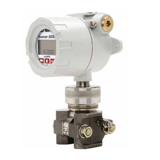
(remove to access keypad) Mount for pole-mount hardware MVT adapter (NACE-compliant MVT available) Multi-variable transmitter Integral vent plugs High pressure/low pressure port indicator Figure 1.1—Scanner 2000 microEFM with integral MVT; MVTs are available with bottom ports (shown) or side ports... - Page 11 3/4 in. to 1 in. adapter CSA-approved union (connects directly to the turbine meter) Figure 1.2—Scanner 2000 microEFM for direct connection to a turbine meter (CSA-approved) Figure 1.3—Scanner 2000 microEFM for direct connection to a Barton 7000 Series turbine meter (ATEX- approved)
-
Page 12: Product Identification
Section 1 Scanner 2000 microEFM ® Product Identification Each device is labeled with a serial tag that identifies the product by model number and serial number and identifies the maximum operating pressure, working pressure, and differential pressure of the integral MVT (Figure 1.4). - Page 13 ATEX-approved model (Part No. 9A-30054002) Explosion-Proof Control Switch, page A-1 for details. The temperature input for Scanner 2000 flow calculations is typically supplied by an RTD. Cameron offers three different types of RTDs to cover both explosionproof and weatherproof applications. RTD Assemblies, page A-3, for details.
- Page 14 An optional seal kit (Part No. 2295583-01) supplied by Cameron contains a jumper, a lead seal assembly, an Allen wrench and a label for properly marking a device. See...
-
Page 15: Table 1.1—Scanner 2000 Microefm Specifications
Scanner 2000 microEFM Section 1 ® Table 1.1—Scanner 2000 microEFM Specifications Electrical Safety Approved by CSA for US and Canada Classification Class I, Div. 1, Groups B, C, D (explosion-proof) (Standard Scanner 2000 Class I, Div. 2, Groups A,B,C,D (non-sparking) and Scanner 2000 with Type 4 enclosure, ANSI 12.27.01 single seal (0 to 3000 psi) - Page 16 Section 1 Scanner 2000 microEFM ® Table 1.1—Scanner 2000 microEFM Specifications Logging Daily records: 768 (>2 years) Interval records: • Adjustable from 5 sec to 12 hours • 2304 (>3 months of 1-hour intervals) with main board • 6392 (>8 months of 1-hour intervals) with main board and expansion...
- Page 17 Scanner 2000 microEFM Section 1 ® Table 1.1—Scanner 2000 microEFM Specifications Flow Rate Calculations Compensated Liquids (Orifice/NuFlo Cone/Turbine): (cont’d) AGA Report No. 3: Orifice Metering of Natural Gas and Other Related Hydrocarbon Fluids; ISO 5167: Measurement of Fluid Flow by Means of Pressure Differential Devices Inserted in Circular Cross-Section Conduits Running Full NuFlo Cone Meter User Manual, www.c-a-m.com (Measurement Systems)
- Page 18 Section 1 Scanner 2000 microEFM ® Table 1.1—Scanner 2000 microEFM Specifications MVT Accuracy Effect on differential pressure for a 100-psi change in static pressure: Max. SP/SWP Overrange (PSIA) (IN H2O) (PSIA) Zero Shift Span Shift ±0.05% of URL ±0.01% of reading ±0.007% of URL...
- Page 19 Scanner 2000 microEFM Section 1 ® Table 1.1—Scanner 2000 microEFM Specifications Inputs (Expansion Board); Analog Input (2) • 3-wire sensor interface not applicable to • 1-5V or 4-20 mA ™ fieldbus • Sensor power same as external power supply for main board (6 to 30...
- Page 20 Section 1 Scanner 2000 microEFM ® Table 1.1—Scanner 2000 microEFM Specifications Output (Expansion Board) Analog Output • 4-20 mA not applicable to • Accuracy: 0.1% of full scale @ 25°C (77°F), 50 PPM/°C (27.8 PPM/°F) ™ fieldbus temperature drift oundation configurations •...
-
Page 21: Power Options
The ModWorX™ Pro interface software is designed for simplicity and ease of use. Its intuitive, well- organized screens allow users to calibrate and configure the Scanner 2000 microEFM within just a few minutes, and download log archives in an easy-to-read report. RTU Modbus protocol and RS-485 ®... -
Page 22: Lcd/Keypad Functions
Figure 1.6—ModWorX™ Pro software interface The standard Scanner 2000 microEFM saves up to 2304 interval logs (interval periods are adjustable from 5 sec to 12 hours ), 768 daily logs, and 1152 event/alarm logs in nonvolatile memory. With the optional expansion board, the Scanner 2000 saves up to 6392 interval logs. -
Page 23: Viewing Real-Time Measurements
Scanner 2000 microEFM Section 1 ® Section 4—Configuration and Operation via Keypad, guides users step by step through the configuration of these parameters using the keypad. Figure 1.7 summarizes the functions that can be accessed with each button. CONFIGURATION: CONFIGURATION: Move between menus Save configuration and menu selections... -
Page 24: Configuring Basic Parameters
Section 1 Scanner 2000 microEFM ® Parameter changes when LEFT ARROW button is pressed Figure 1.8—LCD display of real-time measurements Note If the instrument is equipped with an explosion-proof switch, the user can manually control the pa- rameter displayed without removing the instrument cover. See Appendix A—Scanner 2000 Hardware Options for more information. -
Page 25: Password-Protected Security
Scanner 2000 microEFM Section 1 ® log archive—up to 768 daily logs, 2304 adjustable interval logs, and 1152 event/alarm logs— can be viewed using ModWorX™ Pro software. Volume (or other assigned parameter) Log index (Days since log was created) Date stamp (MMDDYY) Figure 1.10—LCD display of daily logs Password-Protected Security... - Page 26 Section 1 Scanner 2000 microEFM ®...
-
Page 27: Section 2-Installing The Scanner 2000
Section 2—Installing the Scanner 2000 Overview The Scanner 2000 microEFM is fully assembled at the time of shipment and ready for mounting. However, Cameron recommends that operators configure the microEFM prior to mounting if the instrument is to be installed in a hazardous area. The enclosure must be opened to configure the device, either via keypad controls or via software, and once the instrument is mounted in a hazardous area, the cover should not be removed unless the area is void of combustible gas and vapors. -
Page 28: Class I, Div. 1 (Csa) Installations
A 2-wire, 3-wire, or 4-wire RTD assembly may be used. Cameron’s Barton Model 21 RTD, a 4-wire, 100-ohm explosion-proof RTD assembly, can be connected to the Scanner 2000 enclosure without conduit or a conduit seal. For details, see Explosion-Proof RTD Assembly (CSA, Class I, Div. -
Page 29: Class I, Div. 2 (Csa) Installations
Type 4 strain relief is recommended for Div. 2 installations. Pressure Safety Precautions WARNING: Before connecting the Scanner 2000 microEFM to a flow line, consider the pressure rating of the sensor, and the presence of harmful gases. The tubing and fixtures used to connect the sensor to the manifold in the flow line must be manufactured from materials that are appropriate for the pressure ratings of the sensor used. -
Page 30: Mounting Options
2000 microEFM ® Mounting Options The Scanner 2000 microEFM can be mounted using the following methods: • Direct-mount to an orifice or cone type DP meter. The integral multi-variable sensor may be connected to the pressure taps with stabilizers or a heavy wall nipple with adapter flanges, and a 5-valve manifold (Figure 2.1, page... - Page 31 Scanner 2000 microEFM Section 2 ® 5.00 (127) 1/4-18 NPT process connections 4.94 (125.5) 5.32 (135.1) 9.60 (243.8) adapter 2.125 (53.98) 0.32 4.96 (8.1) (126.0) 5.32 (135.1) 5.71 (145.0) Figure 2.1—Scanner 2000 with direct-mount MVT (MVT with bottom ports shown) approx.
- Page 32 Section 2 Scanner 2000 microEFM ® approx. 9.00 (228.6) M20 to 3/4”-14 NPT reducer 3/4”-14 NPT to M20 stand-off tube 7000 Series turbine meter Figure 2.3—Scanner 2000 direct-mounted to a Barton 7000 Series flowmeter (ATEX-approved only when direct-mounted to a Barton 7000 Series flowmeter) Pole mount kit 9.60...
-
Page 33: Measuring Natural Gas Via A Differential Pressure Meter
Scanner 2000 microEFM Section 2 ® Measuring Natural Gas via a Differential Pressure Meter Note This section contains installation guidelines for orifice and cone meters. If installing the Scanner 2000 with an averaging pitot tube meter, refer to manufacturer instructions for installation. Best Practices for Orifice and Cone Meter Installation To ensure measurement accuracy, ensure that the meter run complies with the following AGA-3 and ISO 5167 guidelines, as applicable:... -
Page 34: Installation Procedure-Direct Mount To Orifice Meter Or Cone Meter
Section 2 Scanner 2000 microEFM ® If the Scanner 2000 is mounted to a cone meter, consider the following best practices in addition to the best practices listed above. • Position the cone meter so that there are zero to five pipe diameters upstream of the meter and zero to three pipe diameters downstream of the meter. -
Page 35: Installation Procedure-Remote Mount To Orifice Meter Or Cone Meter
This adapter can be a one-piece stabilizer (often preferred for added strength and stability) or a short heavy wall pipe nipple attached to a futbol flange (available from Cameron). Use a suitable com- pound or tape on all threaded process connections. - Page 36 2. Mount the Scanner 2000 to a 2-in. pipe or to a flat, vertical surface using bolts and the mounting holes in the enclosure. 3. Bolt a 5-valve flange-by-NPT manifold (as recommended by Cameron) to the Scanner 2000 MVT sensor. a. Locate the H and L markings on the integral MVT sensor body and position the MVT/manifold as- sembly so that the upstream side of the flow line can easily be connected to the sensor’s “High”...
- Page 37 Scanner 2000 microEFM Section 2 ® CAUTION Do not use Teflon tape on the threads of the union, adapter, or pipe plugs. Use of ® Teflon tape will void the explosion-proof rating of the instrument. ® 5. Install the RTD assembly in the thermowell. Route the RTD assembly cable through the conduit opening in the top of the Scanner 2000 to connect to the main circuit board.
-
Page 38: Measuring Natural Gas Via A Turbine Meter
Measuring Natural Gas via a Turbine Meter Best Practices The Scanner 2000 microEFM calculates gas flow through a turbine meter in accordance with AGA-7 and API 21.1 industry standards. For optimum performance, ensure that the turbine and Scanner 2000 installation complies with the industry recommendations listed below: •... - Page 39 Scanner 2000 microEFM Section 2 ® 5. Remove the plug from the conduit opening in the top of the Scanner 2000 enclosure, route the turbine sig- nal cable through the opening, and connect it to the main circuit board. A wiring diagram for the turbine input is provided in Figure 3.4, page 65.
-
Page 40: Installation Procedure-Direct Mount To A Turbine Meter (Csa Compliant)
Section 2 Scanner 2000 microEFM ® Installation Procedure—Direct Mount to a Turbine Meter (CSA Compliant) A Scanner 2000 without the MVT bottomworks can be mounted directly to a gas turbine meter for measuring natural gas. A pipe adapter and union are attached to the Scanner, allowing a direct connection to the turbine meter. - Page 41 Scanner 2000 microEFM Section 2 ® 4. Tighten all sections of the pipe union. 5. Connect the pressure port of the turbine meter to the external pressure transducer. 6. Remove the plug from the conduit opening in the top of the Scanner 2000 enclosure, route the cable from the pressure transducer through the opening, and connect it to the analog input terminal of the expansion circuit board.
-
Page 42: Measuring Steam Via A Differential Pressure Meter
Section 2 Scanner 2000 microEFM ® Measuring Steam via a Differential Pressure Meter Note This section contains installation guidelines for orifice and cone meters. If installing the Scanner 2000 with an averaging pitot tube meter, refer to manufacturer instructions for installation. Best Practices The Scanner 2000 calculates steam flow in accordance with IF-97, AGA-3, and ISO-5167 industry standards. -
Page 43: Installation Procedure-Remote Mount To Orifice Meter Or Cone Meter
Scanner 2000 microEFM Section 2 ® CAUTION Before starting the system, remove the caps and add water or antifreeze if necessary to completely fill the pots and cold legs. Air trapped in the lines will produce errors in dif- ferential pressure measurements. Installation Procedure—Remote Mount to Orifice Meter or Cone Meter A Scanner 2000 can be mounted remotely and connected to an orifice meter or cone meter with tubing for steam measurement. - Page 44 If a bottom-port MVT is used, the bottom process ports must be plugged or replaced with a drain valve, and side vents must be used for process connections. A block manifold is not recommended for use with bottom port MVTs. Contact a Cameron field representative for assistance.
- Page 45 Scanner 2000 microEFM Section 2 ® d. Connect a hand pump or funnel to the fitting. e. Pour fill liquid into the funnel or pump it into the cold leg, tapping the cold leg occasionally to dis- lodge any bubbles. Observe the pipe tee/condensate pot and stop pouring when the fill liquid is visible at the top and no air bubbles can be seen.
-
Page 46: Measuring Liquid Via A Differential Pressure Meter
Section 2 Scanner 2000 microEFM ® Measuring Liquid via a Differential Pressure Meter Note This section contains installation guidelines for orifice and cone meters. If installing the Scanner 2000 with an averaging pitot tube meter, refer to manufacturer instructions for installation. Best Practices To ensure measurement accuracy, ensure that the meter run complies with the following AGA-3 and ISO 5167 guidelines, as applicable:... -
Page 47: Installation Procedure-Direct Mount To Orifice Meter Or Cone Meter
Scanner 2000 microEFM Section 2 ® practices listed above. • Position the cone meter so that there are zero to five pipe diameters upstream of the meter and zero to three pipe diameters downstream of the meter. • Install the meter so that the static pressure tap is upstream of the differential pressure tap. The high side of the integral Scanner 2000 sensor must also be situated upstream. -
Page 48: Installation Procedure-Remote Mount To Orifice Meter Or Cone Meter
If a bottom-port MVT is used, the bottom process ports must be plugged or replaced with a drain valve, and side vents must be used for process connections. A block manifold is not recommended for use with bottom port MVTs. Contact a Cameron field representative for assistance. - Page 49 Scanner 2000 microEFM Section 2 ® RTD assembly Shut-off valves throttle flow to the manifold and MVT Positioning of sensor below the meter and slope of tubing helps prevent gas bubbles from entering the liquid Figure 2.11—Remote-mount liquid run installation (shown here with a cone meter). The remote-mount method can be used with an orifice meter as well.
- Page 50 Section 2 Scanner 2000 microEFM ® Important If the process fluid does not present an environmental risk and is stable when depressur- ized, it may be used to bleed air from the lines. If the process fluid can contaminate the environment, or is highly volatile when depressurized as with liquified gases, a different seal fluid should be used to fill the legs.
-
Page 51: Measuring Compensated Liquid Via A Turbine Meter
Measuring Compensated Liquid via a Turbine Meter Best Practices The Scanner 2000 microEFM calculates compensated liquid flow through a turbine meter in accordance with API-2540 and the measurement principles upon which the AGA-7 standard is based. The user supplies a linear or multi-point calibration factor, and the instrument performs the required compensation calculations, based on the RTD input. -
Page 52: Installation Procedure-Direct Mount To A Barton 7000 Series Turbine Meter (Atex Compliant)
Section 2 Scanner 2000 microEFM ® To connect the Scanner 2000 to a liquid turbine meter using this method, perform the following steps: 1. Position the Scanner 2000 above the flowmeter. 2. Plug the Scanner 2000 cable connector into the magnetic pickup of the turbine meter and hand-tighten the knurled nut on the connector. - Page 53 Scanner 2000 microEFM Section 2 ® To connect the Scanner 2000 to a turbine meter using this method, perform the following steps: 1. Position the Scanner 2000 and pickup extension assembly above the flowmeter. 2. Plug the Scanner 2000 cable connector into the magnetic pickup of the turbine meter and hand-tighten the knurled nut on the connector.
-
Page 54: Measuring Uncompensated Liquid Via A Turbine Meter
Measuring Uncompensated Liquid via a Turbine Meter Best Practices The Scanner 2000 microEFM calculates uncompensated liquid flow through a turbine meter in accordance with API MPMS, Chapter 5, Section 3, Measurement of Liquid Hydrocarbons by Turbine Meters. For optimum performance, ensure that the turbine and Scanner 2000 installation complies with the industry recommendations listed below: •... -
Page 55: Installation Procedure-Direct Mount To A Barton 7000 Series Turbine Meter (Atex Compliant)
Scanner 2000 microEFM Section 2 ® Installation Procedure—Direct Mount to a Barton 7000 Series Turbine Meter (ATEX Compliant) A Scanner 2000 without the MVT bottomworks can be mounted directly to a Barton 7000 series turbine meter for measuring liquid (Figure 2.15). A stainless steel turbine meter pickup extension supports the Scanner 2000 and provides the elevation necessary for good visibility of the display. -
Page 56: Zero Offset (Static Pressure Or Differential Pressure)
1500-psi sensor should be verified at 0 psi, 750 psi, and 1500 psi, then at 1200 psi, 300 psi, and 0 psi. WARNING: Do not subject the Scanner 2000 microEFM to unnecessary shock or over-range pressure during maintenance operations. -
Page 57: Differential Pressure Calibration And Verification
200-In. H2O sensor should be verified at 0 In. H2O, 100 In. H2O, 200 In. H2O, then at 160 In. H2O, 40 In. H2O, and 0 In. H2O. WARNING: Do not subject the Scanner 2000 microEFM to unnecessary shock or over-range pressure during maintenance operations. -
Page 58: Placing The Scanner Into Operation
Section 2 Scanner 2000 microEFM ® 7. Apply the same amount of pressure to the high side of the MVT using the simulator (see the ModWorX™ Pro Software User Manual, Part No. 9A-30165025, for complete instructions). The ModWorX™ Pro software will display a measured value. 8. -
Page 59: Industry Standards For Cone Meters
Scanner 2000 microEFM Section 2 ® Table 2.2—Industry Standards for Orifice Meters Standard Applicable Section Description Notes AGA Report No. 3: Part 2: Specification Specifications for orifice This standard is also Orifice Metering of and Installation meters (to include beta ratios) distributed under the Natural Gas and Other Requirements,... -
Page 60: Table 2.3—Industry Standards For Turbine Meters
Section 2 Scanner 2000 microEFM ® Table 2.3—Industry Standards for Turbine Meters Standard Applicable Section Description Notes AGA Report No. 7: Section 7- Installation of gas turbine This specification Measurement of Installation meters to include flow applies to axial-flow Natural Gas by Turbine Specifications direction, meter orientation, turbine flowmeters for... -
Page 61: Section 3-Wiring The Scanner 2000
Scanner 2000 microEFM Section 3 ® Section 3—Wiring the Scanner 2000 Field Wiring Connections WARNING: Do not connect/disconnect equipment or change batteries unless the area is known to be non-hazardous. The Scanner 2000 poses no hazard when opened in a safe area. CAUTION All field wiring must conform to the National Electrical Code, NFPA 70, Article 501-4(b) for installations within the United States or the Canadian Electric Code for installations... -
Page 62: Grounding Procedures
® Grounding Procedures To power the Scanner 2000 microEFM with an external DC supply, route the ground conductor through a conduit opening in the top of the Scanner 2000 enclosure with the power conductors and connect it to the ground screw inside the enclosure (note the round sticker that marks this location in Figure 3.1). -
Page 63: Power Supply Wiring
Power Supply Wiring Internal Power Supply The Scanner 2000 microEFM is shipped with a lithium battery pack. To supply power to the instrument, connect the battery cable to connector J1 on the main circuit assembly (Figure 3.2). Low-power microprocessor technology enables the Scanner 2000 to operate for an estimated 1 year on a lithium battery pack. -
Page 64: External Power Supply
Section 3 Scanner 2000 microEFM ® When an external power supply is used as the primary power source, the lithium battery pack serves as a backup power supply. The use of an alternate power source extends battery life and helps ensure that timekeeping and volume accumulation will not be interrupted during a power failure. -
Page 65: Input Wiring
Scanner 2000 microEFM Section 3 ® Input Wiring Turbine Flowmeter Input The Turbine Input 1 on the main circuit board provides the turbine flowmeter input signal generated by a magnetic pickup, enabling the Scanner 2000 to calculate and display instantaneous flow rates and accumulated totals. -
Page 66: Rtd Input
Section 3 Scanner 2000 microEFM ® RTD Input The RTDs described in Appendix A of this manual are recommended for measuring temperature for use in temperature-compensated gas and liquid calculations, though a 2- or 3-wire RTD may prove functional. Wiring is essentially the same for all three models, though wire color may vary as indicated. Wire as shown in Figure 3.5. -
Page 67: Output Wiring
Scanner 2000 microEFM Section 3 ® Output Wiring Digital Output (Pulse or Alarm) The standard Scanner 2000 supports a solid-state digital output that is configurable as either a pulse output or an alarm output. As a pulse output, the pulse width duration and pulse representation are both configurable. Because the circuit is isolated, it can be used in conjunction with any other feature on the Scanner 2000. -
Page 68: Rs-485 Output-Permanent Computer Connection
Section 3 Scanner 2000 microEFM ® RS-485 Output—Permanent Computer Connection The RS-485 output is required for communication with the interface software. The wiring diagram in Figure 3.7 supports a permanent connection. PORT 2 RS-485 COMMUNICATIONS – SCANNER 2000 Main Circuit Board PN: 9A-30160010 PORT 1 RS-485 COMMUNICATIONS... -
Page 69: Rs-485 Output-Laptop Computer Connection
Scanner 2000 microEFM Section 3 ® RS-485 Output—Laptop Computer Connection The RS-485 output is required for communication with the interface software. The wiring diagram in Figure 3.8 supports a temporary laptop connections using an RS-232 to RS-485 converter. SCANNER 2000 Main Circuit Board PN: 9A-30160010 PORT 2 CONNECTIONS ARE... -
Page 70: Configuration Via Keypad
An RS-232 to RS-485 converter or NuFlo USB adapter is required for connecting the microEFM to a laptop or PC. The converters available from Cameron require no handshaking or external power to operate. See Section 6—Spare Parts for ordering information; see Figure 3.7, page... -
Page 71: Section 4-Configuration And Operation Via Keypad
For this reason, it is important to configure these settings before installing it in a hazardous area. WARNING: To prevent ignition of hazardous atmospheres, do not remove the cover while cir- cuits are alive. The Scanner 2000 microEFM poses no hazard when opened in a safe area. CONFIGURATION:... -
Page 72: Entering The Slave Address
Section 4 Scanner 2000 microEFM ® Entering the Slave Address The slave address is a setting used in Modbus communications. It is a number that ranges from 1 to 65535, ® excluding 252 to 255 and 64764, which are reserved. If the Modbus request message contains the matching ®... -
Page 73: Entering The Baud Rate
Scanner 2000 microEFM Section 4 ® Entering the Baud Rate The baud rate is the number of bits per second that are on the serial port. This setting must match the setting of the master device polling the Scanner 2000 or the serial port. This only applies to the Modbus communi- ®... -
Page 74: Editing The Date And Time
Section 4 Scanner 2000 microEFM ® Editing the Date and Time A user can change the date and time from the keypad. To Edit the Date and Time: Enter the Access menu. Press UP ARROW and ENTER simultaneously. Locate the Date and Time setting. Press ENTER four times. -
Page 75: Editing The Contract Hour
Scanner 2000 microEFM Section 4 ® Editing the Contract Hour A user can set the contract hour from the keypad. The contract hour determines the exact time the daily flow is logged, and is represented by a four-digit number displayed in military time. To Edit the Contract Hour: Enter the Access menu. -
Page 76: Editing The Plate Size
Section 4 Scanner 2000 microEFM ® Editing the Plate Size When the differential pressure producer in a Scanner 2000 installation is an orifice meter and security controls allow, a user can change the size of the orifice plate from the keypad. The plate size is displayed in inches. If “Strict API compliance”... -
Page 77: Section 5-Scanner 2000 Maintenance
Scanner 2000 microEFM Section 5 ® Section 5—Scanner 2000 Maintenance The Scanner 2000 is engineered to provide years of dependable service with minimal maintenance. Batteries require periodic replacement, and battery life depends on whether battery power is the primary or secondary power source, the configuration settings of the Scanner 2000, and ambient temperature conditions. -
Page 78: Circuit Assembly Replacement
Section 5 Scanner 2000 microEFM ® 3. Lift the display/keypad assembly from the enclosure, making sure the circuit assembly does not contact the enclosure. 4. Loosen the velcro strap, disconnect the battery from the J1 connector on the circuit assembly, and remove the spent battery pack from the enclosure (Figure 5.1). - Page 79 Scanner 2000 microEFM Section 5 ® Important If possible, download the configuration settings and all archive logs before replacing the circuit board. Press the ENTER/SAVE key on the keypad before disconnecting the bat- tery to save accumulated flow run and turbine volume totals (grand total and current day total), and energy and mass totals to memory.
- Page 80 Section 5 Scanner 2000 microEFM ® Figure 5.3—Disassembly of circuit board/keypad assembly Figure 5.4—To release the ribbon cable from the connector, press in on the side tabs of the J7 connector (white arrows) and gently pull forward (black arrow). 13. Connect the circuit board to the keypad with the two #4-40 × 5/16” screws removed in step 9. 14.
-
Page 81: Keypad Replacement
Scanner 2000 microEFM Section 5 ® 18. Recalibrate the Scanner 2000 and replace the enclosure cover. Important Do not overlook the need to recalibrate the Scanner 2000. Boards that are shipped inde- pendently of a Scanner 2000 are not calibrated to compensate for atmospheric pressure; therefore, a Scanner 2000 will not display accurate pressure readings until it is recalibrated. -
Page 82: Mvt Replacement
Section 5 Scanner 2000 microEFM ® MVT Replacement Important Press the ENTER/SAVE key on the keypad before disconnecting the battery to save ac- cumulated flow run and turbine volume totals (grand total and current day total), and energy and mass totals to memory. To replace the MVT of the Scanner 2000, perform the following steps: 1. -
Page 83: Section 6-Spare Parts
WARNING: EXPLOSION HAZARD – Substitution of components may impair suitability for Class I, Division 1 and 2. Use of spare parts other than those identified by Cameron Internation- al Corporation voids hazardous area certification. Cameron bears no legal responsibility for the performance of a product that has been serviced or repaired with parts that are not authorized by Cameron. -
Page 84: Table 6.2—Scanner 2000 Microefm Spare Parts (Atex-Approved)
Assembly, Installation Software CD and CD Pocket Folder, ModWorX™ Pro Table 6.4 Multi-Variable Transmitter (selection based on pressure requirements) Table 6.2—Scanner 2000 microEFM Spare Parts (ATEX-Approved) 9A-30099006 Battery Pack, 2 “D” Batteries in Series, 7.2V, Lithium, with Current Limiting Resistor and Diode 9A-30188004... -
Page 85: Table 6.3—Rtd And Cable Assemblies (Csa-Approved)
Scanner 2000 microEFM Section 6 ® Table 6.2—Scanner 2000 microEFM Spare Parts (ATEX-Approved) 9A-30025004 Tube, Standoff, Stainless Steel, 1.18 in. Hex X 12.00 in. long with 3/4 in. NPT Male & Female Ends 9A-30025005 Tube, Standoff, Stainless Steel, 1.18 in. Hex X 18.00 in. long with 3/4 in. - Page 86 Section 6 Scanner 2000 microEFM ® Table 6.4—Multi-Variable Transmitters Select one based on specific application. The MVTs listed below have bottom ports. Side port models are available on request. 9A-99168081 9A-99168092 9A-99168107 3000 PSIA, 400 IN H2O 9A-99168082 9A-99168093 9A-99168108 3000 PSIA, 840 IN H2O 9A-99168045 9A-99168050...
-
Page 87: Appendix A-Scanner 2000 Hardware Options
Figure A.2—Dimensions of explosion-proof control switch; inches (mm) If the switch is ordered with a Scanner 2000 microEFM, it will be installed prior to shipment. To add a switch to an existing Scanner 2000, terminate the leads to connector J2 on the main circuit board (Figure A.3). - Page 88 Appendix A Scanner 2000 microEFM ® SCANNER 2000 Main Circuit Board PN: 9A-30160010 BATTERY Figure A.3—Wiring of explosion-proof control switch To select a display parameter for viewing, press and release the push-button switch. With each subsequent press of the switch, the LCD will display a new parameter (Figure A.4). Parameters will appear in the order specified by the user when he configured the display.
-
Page 89: Rtd Assemblies
Flameproof RTD Assembly (ATEX, Zone 1) Cameron offers a flameproof RTD that is ATEX-certified for use in Zone 1 installations. The 4-wire, Class A sensor is encapsulated in a stainless steel sheath long enough to accommodate line sizes from 2 to 12 inches. -
Page 90: Communications Adapter (Csa Div. 1 Or Div. 2, Atex Zone 1
Separate part numbers are provided for CSA and ATEX models, as the ATEX model is constructed with ATEX-approved materials. An RS-232 to RS-485 converter cable (available from Cameron’s Measurement Systems Division) is required for connecting the adapter to a laptop computer. A variety of converter cable options are listed in the Spare... - Page 91 CONVERTER +12V Part No. 101283116 Figure A.9—Wiring of plug connector to Cameron 9-pin RS-232 to RS-485 converter cable 3. Insert the plug connector into the adapter socket. 4. Connect the converter cable to the PC or laptop. To disconnect the adapter, remove the plug connector (with converter cable attached) from the socket, place the blanking plug inside the union nut (removed in step 1) and screw the union nut onto the union half to cover the socket.
-
Page 92: Communications Adapter Installation (For Adapters Purchased Separately From A Scanner 2000
Do not remove the plug from the enclosure to install the adapter unless the area is known to be non-hazardous. To install a communications adapter purchased separately from a Scanner 2000 microEFM, perform the following steps: 1. Thread the cable of the adapter through a conduit opening in the instrument housing and screw the adapter into place. -
Page 93: Using The Adapter
Scanner 2000 microEFM Appendix A ® Figure A.10—NuFlo USB adapter Figure A.11—NuFlo USB adapter components Using the Adapter The CD supplied with the NuFlo USB Adapter contains the drivers required to enable USB communications for a Scanner 2000 when the NuFLo USB Adapter is installed. For step-by-step installation instructions, insert the CD in your computer and follow the instructions in the NuFlo USB Adapter_Readme file. -
Page 94: Adapter Kit Installation
With the installation of the Scanner 2000 input/output expansion board, the instrument can support up to three flow runs simultaneously—a flow run and two turbine meter runs. All inputs and outputs are configured with ModWorX™ Pro software provided with each Scanner 2000 microEFM. See the ModWorX™ Pro Software User Manual, Part No. 9A-30165025, for details. -
Page 95: Installation (For Boards Purchased Separately From A Scanner 2000
Scanner 2000 microEFM Appendix A ® If the expansion board is ordered with a Scanner 2000, it is installed at the factory. If the board is purchased separately, the user will need to install it on the Scanner 2000 main board using the following instructions. Installation (for boards purchased separately from a Scanner 2000) Important Before installing the expansion board, remove all power from the Scanner 2000... -
Page 96: Wiring Diagrams
Appendix A Scanner 2000 microEFM ® Wiring Diagrams Analog Inputs 1 and 2 The analog inputs, which can be configured for a 0-5 V, 1-5 V or 4-20 mA signal, can be used to receive readings from a pressure or temperature transmitter for use in AGA-7 gas calculations. Alternatively, they can be used to log measurements from any device with a 0-5 V, 1-5 V or 4-20 mA output. - Page 97 Scanner 2000 microEFM Appendix A ® Pulse Input The pulse input provides an optically isolated input for high-amplitude pulse (frequency) signals, which includes signals from a turbine meter equipped with a preamplifier (Figure A.16, top diagram) or signals from a positive displacement meter (Figure A.16, bottom diagram). The Scanner 2000 can calculate flow from no more than two pulse (frequency) inputs at a time.
- Page 98 Appendix A Scanner 2000 microEFM ® Turbine Flowmeter Input 2 Turbine Input 2 (Figure A.17) accepts a turbine flowmeter input signal generated by a magnetic pickup. The Scanner 2000 can be configured to use this signal to calculate and display instantaneous flow rates and accumulated totals.
- Page 99 Scanner 2000 microEFM Appendix A ® ANALOG OUTPUT (TB4) (WITH POWER SUPPLIED VIA MAIN BOARD (TB2) ANALOG DEVICE POWER SUPPLY Resistor may be included in readout 8-30 VDC device. GROUND SCREW INSIDE ENCLOSURE Expansion Board PN: 9A-30160014 SCANNER 2000 Main Circuit Board PN: 9A-30160010 1100 OPERATING...
-
Page 100: Measurement Canada Seal Kit
Appendix A Scanner 2000 microEFM ® Measurement Canada Seal Kit Measurement Canada has approved the use of the Scanner 2000 for custody transfer applications when it is installed in accordance with the configuration and sealing provisions cited in Measurement Canada Approval No. - Page 101 Scanner 2000 microEFM Appendix A ® SCANNER 2000 Main Circuit Board PN: 9A-30160010 BATTERY Figure A.19—J2 receptacle for installing the seal kit jumper 5. Complete field wiring, if applicable, while the circuit board is exposed. 6. Reposition the switchplate and circuit board assembly against the standoffs and secure by replacing one of the switchplate screws that was removed in step 3.
-
Page 102: Terminal Housing
Figure A.21—Scanner 2000 with seal kit installed Terminal Housing Cameron’s Model TH4 terminal housing (Figure A.22 and Figure A.23, page A-17) expands the number of I/O and instrument connections that can be added to a Scanner 2000. It features a six-position terminal strip and four 3/4-in. - Page 103 Scanner 2000 microEFM Appendix A ® simplify field wiring. Then, once in the field, the user connects all field wiring directly to the terminal strip without opening the Scanner 2000 enclosure. The terminal housing is available with either brass or stainless steel plugs. Figure A.22—Model TH4 terminal housing with cover removed Figure A.23—Typical installation of Scanner 2000 with Model TH4 terminal housing A-17...
- Page 104 Appendix A Scanner 2000 microEFM ® A-18...
-
Page 105: Appendix B-Lithium Battery Information
Shipping of lithium batteries on road and rail is regulated by requirements in special provisions 188, 230 and 310, latest revision. Material Safety Data Sheet For a link to the current MSDS for the lithium batteries used to power the Scanner 2000 microEFM, see the Measurement Systems Division section of the Cameron website: www.c-a-m.com. - Page 106 Appendix B Scanner 2000 microEFM ®...
-
Page 107: Appendix C-Scanner 2000 For F Overview
Scanner 2000 microEFM Appendix C ® Appendix C—Scanner 2000 for F ™ Fieldbus oundation Overview The NuFlo™ Scanner 2000 microEFM for F ™ Fieldbus communicates via both RTU Modbus ® ® oundation and H1 fieldbus protocol. The device computes volumes of gas, liquid and steam using a differential pressure or pulse output from a primary metering device and makes the data available for download via Modbus ®... -
Page 108: Hardware Options
Table C.1 contains specifications that are specific to F ™ fieldbus devices. See Table 1.1—Scanner oundation 2000 microEFM Specifications, page 15 for all other specifications. Table C.1—Scanner 2000 microEFM Specifications (Fieldbus Devices Only) System Power Fieldbus power supply • Connects to fieldbus interface board •... -
Page 109: Installing The Scanner 2000
Scanner 2000 microEFM Appendix C ® Table C.1—Scanner 2000 microEFM Specifications (Fieldbus Devices Only) ™ Fieldbus Fieldbus power/communications port on fieldbus interface board oundation Fieldbus module contains 1 resource block, 1 transducer block, and 4 analog input blocks Device is capable of being a link master and a link active scheduler... -
Page 110: Mounting Options
Appendix C Scanner 2000 microEFM ® HOST HAZARDOUS AREA LINKING DEVICE POWER SUPPLY TERM TERM SAFE AREA Figure C.2—Basic installation Mounting Options For instructions on mounting the Scanner 2000, see Mounting Options, page Field Wiring Connections WARNING: To prevent ignition of hazardous atmospheres, do not remove the cover while cir- cuits are alive. -
Page 111: Fieldbus Cable
Scanner 2000 microEFM Appendix C ® • The fieldbus interface board includes terminals for F ™ fieldbus power/communications. oundation A white potted fieldbus module (Figure C.3, page C-5) is attached to the fieldbus interface board, but it has no customer inputs/outputs. It is used solely for converting Modbus signals received from the main board to ®... -
Page 112: Grounding Procedures
Appendix C Scanner 2000 microEFM ® To wire the Scanner 2000 for operation, complete the following field connections: 1. Unscrew and remove the cover from the Scanner 2000 enclosure. 2. Using a small standard blade screwdriver, remove the two #4-40 × 7/8” screws located to the right and left side of the display. -
Page 113: Lithium Battery Pack
Figure C.4—Ground screw locations Lithium Battery Pack The Scanner 2000 microEFM is shipped with a lithium battery pack. In F ™ fieldbus applications, oundation this battery pack provides backup power. Primary power is provided by a fieldbus power supply. -
Page 114: Terminal Housing Wiring Options
Appendix C Scanner 2000 microEFM ® CAUTION Always connect the lithium battery to the main board before connecting fieldbus power to the fieldbus interface board. See also Internal Power Supply, page Figure C.5—F ™ fieldbus power supply wiring without junction box oundation Terminal Housing Wiring Options The standard Scanner 2000 provides two conduit entries for input cable. -
Page 115: Device Configuration
Scanner 2000 microEFM Appendix C ® TO SCANNER 2000 MAIN BOARD, TB1, TERMINALS 1-4 JUNCTION BOX (OPTIONAL) FROM RTD (4-WIRE RECOMMENDED) Figure C.7— F ™ fieldbus process temperature input wiring with junction box oundation Device Configuration Basic parameters such as communications port slave address and baud rate, date and time, contract hour, and plate size can be configured from the device keypad (Configuration via Keypad, page 70). -
Page 116: Device Description
DD files are downloaded to the host in preparation for configuring the device. These files are available on the Fieldbus Foundation™ website (www.fieldbus.org) and the Cameron website (www.c-a-m.com/flo). There are two device description files and one capabilities file (CFF). All three files must be downloaded in order for the host to identify the Scanner 2000 as a networked device. -
Page 117: Device Identification
Scanner 2000 microEFM Appendix C ® The Resource State parameter shows the status of the hardware. If the hardware is working as designed, the status is displayed as “online.” If the resource block is placed in OOS mode, the status will be “Standby.” If a hardware failure occurs, the resource state will be “Failure.”... -
Page 118: Configuring Fieldbus Communications
Each Scanner 2000 has a 32-character hardware identifier that is unique to each unit. This address is set by Cameron, stored in the firmware for the device, and cannot be changed. The Scanner 2000 Device ID is 43414DXXXX_FBK_YYY where XXXX is the device type indicator, and YYY is the serial number for the fieldbus module. - Page 119 Scanner 2000 microEFM Appendix C ® Setup of the configuration tool and download of the network configuration to the Scanner 2000 will vary with product manufacturers. See the host manual or the configuration tool manual for detailed instructions. CAUTION If installing multiple devices, verify that each device has a unique node address. If two or more units have the same node address, the configuration software will not detect more than one unit.
- Page 120 Appendix C Scanner 2000 microEFM ® 5. Set the XD-SCALE parameter. This setting defines the input values from the transducer block (input range of sensor) that correspond to 0% and 100% values in AI function block calculations. When the desired output is the measured variable (L_TYPE is set to direct), set the XD_SCALE to represent the operating range of the sensor.
-
Page 121: Fieldbus Operations
Scanner 2000 microEFM Appendix C ® Fieldbus Operations The Foundation™ Fieldbus Protocol Manual for Scanner 2000 provides a list of the parameters supported by the Scanner 2000 fieldbus module. Neither resource blocks nor transducer blocks can be linked to other function blocks to build a control strategy. -
Page 122: Communication Faults
Appendix C Scanner 2000 microEFM ® (BLOCK_ERR) parameter for possible causes. Remember to check the mode of the resource block. If it is in OOS mode, all other blocks will automatically be placed in OOS mode as well. The block error parameter provides an overview of hardware and software erors. It is effective in tracing a wide variety of errors including block configuration errors, link configuration errors, fault state forced, need for maintenance, input/output/memory failure, and lost data. -
Page 123: Board Replacement
Scanner 2000 microEFM Appendix C ® Board Replacement The Scanner 2000 electronic circuitry includes three boards (Figure C.8). The main board (on bottom of the board stack when the assembly is removed from the enclosure) is attached to a smaller fieldbus interface board, which is in turn attached to a white potted fieldbus module. - Page 124 Appendix C Scanner 2000 microEFM ® 4. Record the locations of all cable connections to the main board. 5. Disconnect the fieldbus input cable from terminal block TB4 on the fieldbus interface board (Figure C.9). 6. Unplug the battery cable from connector J1 on the main board (Figure C.9). 7.
- Page 125 Scanner 2000 microEFM Appendix C ® Figure C.11—Removal of the fieldbus interface board 10. Disconnect the sensor ribbon cable from the J5 connector on the main board as follows: a. Lift the latch from the black clip securing the ribbon cable (Figure C.12). b.
- Page 126 Appendix C Scanner 2000 microEFM ® 11. Remove the main board/keypad assembly from the enclosure. 12. Remove the two #4-40 × 5/16” screws fastening the main board to the keypad (Figure C.13). 13. Remove the keypad ribbon cable from the J7 connector on the LCD side of the main board by pressing in on the sides of the black plastic clip and pulling gently on the clip.
- Page 127 Scanner 2000 microEFM Appendix C ® 16. Connect the main board to the keypad with the two #4-40 × 5/16” screws removed in step 12. 17. Reconnect the sensor ribbon cable to the J5 connector at the top of the main board, by inserting the ribbon cable into the black clip and securing the latch on the clip to hold it tightly in place.
-
Page 128: Spare Parts
Use of spare parts other than those identified by Cameron International Corporation voids hazardous area certification. Cameron bears no legal responsibility for the performance of a product that has been serviced or repaired with parts that are not authorized by Cameron. Table C.2—Scanner 2000 microEFM Spare Parts... -
Page 129: Appendix D-Modbus ® Communications Protocol
Scanner 2000 microEFM Appendix D ® Appendix D—Modbus Communications Protocol ® Firmware Version: 4.10 Register Table Version: 15 Introduction The communications protocol for the Scanner 2000 is in accordance with Modicon, Inc. RTU Mode Modbus® as described in Modicon Modbus Protocol Reference Guide, PI-MBUS-300 Rev. J, June 1996. All registers are implemented as 4X or holding registers. -
Page 130: Data Types
Appendix D Scanner 2000 microEFM ® • Port BusDelay • Port BusTimeout • Real Date • Real Time Data Types Various data types are implemented in the Scanner 2000. The following table lists the formats and the numbers of bytes and registers associated with each type. Data Type Byte Count Register Count... -
Page 131: Security
Scanner 2000 communications port must be set to the default (unrestricted) state. If a different security level is required, contact Cameron technical support for details. Security levels can be restored to default permissions with ModWorX Pro software. - Page 132 Appendix D Scanner 2000 microEFM ® Starting Register User-Defined Holding Registers 9100 Device Status 9900 Note: All registers cited in this document refer to the address of the register that appears in the actual Modbus® message. For example, register 8000 has an address of 0x1F40 hexadecimal in the message.
-
Page 133: Product Code
Scanner 2000 microEFM Appendix D ® System Configuration Register Register Data (Decimal) (Hex) Description Type Access 1000 Product Code and Feature Privileges 1001 Register Table Version 1002 Firmware Version 1003 Manufacture Date 1004 Sales Date 1005 Serial Number High 1006 Serial Number Low 1007 Sensor Serial Number[0]... - Page 134 Appendix D Scanner 2000 microEFM ® Communications Configuration Register Register Data (Decimal) (Hex) Description Type Access Default 1100 Port 1 - Port Usage 0 - Slave 1 - Master 1101 Port 1 Slave Address [1 to 65535, excluding 252 to 255 and 64764] 1102 Port 1 - Baud Rate 0 - 300...
- Page 135 Scanner 2000 microEFM Appendix D ® Power Configuration Register Register Data (Decimal) (Hex) Description Type Access Default 1300 Power Mode 0 - High Power 1 - Low Power 1301 Clock Override 1302 Internal System Sample Period 3600 [number of seconds between battery voltage and electronics temperature measurements] 1303...
- Page 136 Appendix D Scanner 2000 microEFM ® Archive Configuration Register Register Data (Decimal) (Hex) Description Type Access Default 1418 Archive Field 11 T1 Run Time 1419 Archive Field 12 Unused 1420 Archive Field 13 Unused 1421 Archive Field 14 Unused 1422 Archive Field 15 Unused 1423...
- Page 137 Scanner 2000 microEFM Appendix D ® Turbine 1 Calibration Register Register Data (Decimal) (Hex) Description Type Access Default 2030 T1 - Calibration Type 2031 T1 - Linear Factor 900.00 2033 T1 - Calibration Absolute Offset 0.00 2035 T1 - Factor 1 900.00 2037 T1 - Factor 2...
- Page 138 Appendix D Scanner 2000 microEFM ® Turbine 2 Configuration Register Register Data (Decimal) (Hex) Description Type Access Default 2100 T2 - Units 102 – BBL Units Table 2101 T2 - Time Base 3 – Day 2102 T2 - Sampling Period (sec) 2103 T2 - Dampening Factor 2104...
- Page 139 Scanner 2000 microEFM Appendix D ® Turbine 2 Calibration Register Register Data (Decimal) (Hex) Description Type Access Default 2153 T2 - Factor 10 1.00 2155 T2 - Factor 11 1.00 2157 T2 - Factor 12 1.00 2159 T2 - Frequency 1 1.00 2161 T2 - Frequency 2...
- Page 140 Appendix D Scanner 2000 microEFM ® Static Pressure Configuration Register Register Data (Decimal) (Hex) Description Type Access Default 2222 SP - Unit Description 1 2223 SP - Unit Description 2 2224 SP - Unit Description 3 Static Pressure Calibration Register Register Data (Decimal)
- Page 141 Scanner 2000 microEFM Appendix D ® RTD Configuration Register Register Data (Decimal) (Hex) Description Type Access Default 2300 PT - Units Units Table 2301 PT - Time Base 0 = Second 1 = Minute 2 = Hour 3 = Day 2302 PT - Sampling Period (sec) 2303...
- Page 142 Appendix D Scanner 2000 microEFM ® RTD Calibration Register Register Data (Decimal) (Hex) Description Type Access Default 2353 PT - Calibration Actual 10 0.00 2355 PT - Calibration Actual 11 0.00 2357 PT - Calibration Actual 12 0.00 2359 PT - Calibration Measured 1 0.00 2361 PT - Calibration Measured 2...
- Page 143 Scanner 2000 microEFM Appendix D ® Differential Pressure Configuration Register Register Data (Decimal) (Hex) Description Type Access Default 2418 DP - Units Scale Factor 1.00 2420 DP - Units Offset Factor 0.00 2422 DP - Unit Description 1 — 2423 DP - Unit Description 2 —...
-
Page 144: Analog Input 1 Calibration
Appendix D Scanner 2000 microEFM ® Analog Input 1 Configuration Register Register Data (Decimal) (Hex) Description Type Access Default 2500 A1 - Units 2501 A1 - Time Base 2502 A1 - Sampling Period 2503 A1 - Dampening Factor 2504 A1 - Input Configuration 2505 A1 - Override Enable 2506... -
Page 145: Analog Input 2 Configuration
Scanner 2000 microEFM Appendix D ® Analog Input 1 Calibration Register Register Data (Decimal) (Hex) Description Type Access Default 2567 A1 - Calibration Measured 5 0.00 2569 A1 - Calibration Measured 6 0.00 2571 A1 - Calibration Measured 7 0.00 2573 A1 - Calibration Measured 8 0.00... -
Page 146: Digital Input Configuration
Appendix D Scanner 2000 microEFM ® Analog Input 2 Calibration Register Register Data (Decimal) (Hex) Description Type Access Default 2639 A2 - Calibration Actual 3 0.00 2641 A2 - Calibration Actual 4 0.00 2643 A2 - Calibration Actual 5 0.00 2645 A2 - Calibration Actual 6 0.00... - Page 147 Scanner 2000 microEFM Appendix D ® Flow Run 1 Configuration Register Register Data (Decimal) (Hex) Description Type Access Default 3004 FR1 Flow Rate Calculation (See definition.) 3005 FR1 Override Enable 0 - Disabled 1 - Enabled 3006 FR1 Fluid Properties 3000 (See definition.) 3007...
- Page 148 Flow Run 1 Configuration Register Register Data (Decimal) (Hex) Description Type Access Default 3033 FR1 Pipe Reference Temp 68.00 Deg F 3035 FR1 Plate Size 1.00 in. 3037 FR1 Plate Reference Temp 68.00 Deg F 3039 FR1 Isentropic Exponent - k 1.30 3041 FR1 Viscosity...
-
Page 149: Flow Rate Calculation Register
Flow Run 1 Configuration Register Register Data (Decimal) (Hex) Description Type Access Default 3099 FR1 GC - N-Decane (n-C10) 0.00 3101 FR1 GC - Helium (He) 0.00 3103 FR1 GC - Argon (Ar) 0.00 3105 FR1 Unit Scale 1.00 3107 FR1 Unit Offset 0.00 3109... -
Page 150: Fluid Property Register
Appendix D Scanner 2000 microEFM ® Flow Rate Calculation ISA Nozzle (FUTURE) Long Radius Nozzle (FUTURE) Averaging Pitot Tube (Annubar®) Fluid Property Register Isen LiqDC HVRef Fluid Property Calc HV - Heating Value Selection Calculated Manual Entry SG - Specific Gravity Selection Calculated Manual Entry V - Viscosity Selection... -
Page 151: Tap Type Register
Scanner 2000 microEFM Appendix D ® Fluid Property Calculation Crude Oil Gasolines Jet Fuels Fuel Oils Lube Oils Tap Type Register Tap Type Loc (Pressure Tap Location) Upstream Downstream Tap Type Flange Corner D and D/2 Reserved Reserved Reserved Reserved Reserved Flow Run 1 Calibration Register... -
Page 152: Output Configuration
Appendix D Scanner 2000 microEFM ® Flow Run 1 Calibration Register Register Data (Decimal) (Hex) Description Type Access Default 3233 FR1 Flow Coefficient 15 0.00 3235 FR1 Flow Coefficient 16 0.00 3237 FR1 Reynolds Number 1 1.00 3239 FR1 Reynolds Number 2 0.00 3241 FR1 Reynolds Number 3... -
Page 153: Pulse Input For Status Indication
Scanner 2000 microEFM Appendix D ® Output Configuration Register Register Data Description Access Default (Decimal) (Hex) Type 4053 Analog Out 2 - High Adjust 4095 4054 Analog Out 3 - Source 4055 Analog Out 3 - Low Value 4057 Analog Out 3 - High Value 1700 4059 Analog Out 3 - Low Adjust... - Page 154 Appendix D Scanner 2000 microEFM ® Holding Registers Register Register (Decimal) (Hex) Description Data Type Access 8028 1F5C FR1 Instantaneous Flow Rate 8030 1F5E FR1 Daily Total 8032 1F60 FR1 Interval Total 8034 1F62 FR1 Polling Total 8036 1F64 FR1 Previous Day Total 8038 1F66 FR1 Previous Interval...
- Page 155 Scanner 2000 microEFM Appendix D ® Holding Registers Register Register (Decimal) (Hex) Description Data Type Access 8108 1FAC FR1 Base Density 8110 1FAE FR1 Average Molecular Weight 8112 1FB0 FR1 Molar Fraction Sum 8114 1FB2 FR1 Mass Heating Value 8116 1FB4 FR1 Heating Value Volume Basis 8118...
- Page 156 Appendix D Scanner 2000 microEFM ® Holding Registers Register Register (Decimal) (Hex) Description Data Type Access 8190 1FFE FR1 Grand Energy Total [MMBTU] FR1 Instantaneous Energy Rate 8192 2000 [MMBTU] 8194 2002 FR1 Daily Energy Total [MMBTU] 8196 2004 FR1 Interval Energy Total [MMBTU] 8198 2006 FR1 Polling Energy Total [MMBTU]...
- Page 157 Scanner 2000 microEFM Appendix D ® Holding Registers Register Register (Decimal) (Hex) Description Data Type Access 8270 204E T1 Previous Month Total [GAL] 8272 2050 T1 Frequency 8274 2052 T1 Active K-Factor 8276 2054 T2 Grand Total 8278 2056 T2 Instantaneous Flow Rate 8280 2058 T2 Daily Total...
- Page 158 Appendix D Scanner 2000 microEFM ® Holding Registers Register Register (Decimal) (Hex) Description Data Type Access 8352 20A0 SP Daily Run Time 8354 20A2 SP Interval Run Time 8356 20A4 SP Polling Run Time 8358 20A6 SP Previous Daily Run Time 8360 20A8 SP Previous Interval Run Time...
- Page 159 Scanner 2000 microEFM Appendix D ® Holding Registers Register Register (Decimal) (Hex) Description Data Type Access 8434 20F2 PT Previous Daily Average 8436 20F4 PT Previous Interval Average 8438 20F6 PT Previous Polling Average 8440 20F8 PT Daily Run Time 8442 20FA PT Interval Run Time...
- Page 160 Appendix D Scanner 2000 microEFM ® Holding Registers Register Register (Decimal) (Hex) Description Data Type Access 8516 2144 A2 Daily Average 8518 2146 A2 Interval Average 8520 2148 A2 Polling Average 8522 214A A2 Previous Daily Average 8524 214C A2 Previous Interval Average 8526 214E A2 Previous Polling Average...
- Page 161 Scanner 2000 microEFM Appendix D ® Holding Registers Register Register (Decimal) (Hex) Description Data Type Access 8596 2194 PID Stage 2 Output 8598 2196 PO1 Pulses 8600 to Reserved 8605 8606 219E AO1 Output Current 8608 21A0 AO2 Output Current 8610 21A2 AO3 Output Current...
-
Page 162: Flow Calculation Parameter Registers (1-16
Appendix D Scanner 2000 microEFM ® Flow Calculation Parameter Registers (1-16) The Flow Calculation Parameter Registers definition is dependent upon the flow rate calculation method that is implemented. The following table describes the function of each of these registers for each of the supported calculation methods. -
Page 163: Interval/Daily/Event Pointer Registers
Scanner 2000 microEFM Appendix D ® Interval/Daily/Event Pointer Registers These registers provide an index of the last record that was stored in the log data. These values start at 1 and increment with each newly created log. When the maximum number of records is reached, the pointer resets to 1 and starts incrementing again. - Page 164 Appendix D Scanner 2000 microEFM ® Holding Registers (32-bit) Register Register Data (Decimal) (Hex) Description Type Access 7036 1B7C FR1 Previous Polling Energy 7037 1B7D FR1 Daily Estimated Total 7038 1B7E FR1 Monthly Total 7039 1B7F FR1 Previous Month Total 7040 1B80 FR1 Daily Run Time...
- Page 165 Scanner 2000 microEFM Appendix D ® Holding Registers (32-bit) Register Register Data (Decimal) (Hex) Description Type Access 7077 1BA5 FR1 Calculation Parameter 15 7078 1BA6 FR1 Calculation Parameter 16 7079 1BA7 FR1 Grand Total [MCF] 7080 1BA8 FR1 Instantaneous Flow Rate [MCF] 7081 1BA9 FR1 Daily Total [MCF]...
- Page 166 Appendix D Scanner 2000 microEFM ® Holding Registers (32-bit) Register Register Data (Decimal) (Hex) Description Type Access 7118 1BCE T1 Previous Month Total 7119 1BCF T1 Daily Run Time 7120 1BD0 T1 Interval Run Time 7121 1BD1 T1 Polling Run Time 7122 1BD2 T1 Previous Daily Run Time...
- Page 167 Scanner 2000 microEFM Appendix D ® Holding Registers (32-bit) Register Register Data (Decimal) (Hex) Description Type Access 7159 1BF7 T2 Polling Total [GAL] 7160 1BF8 T2 Previous Day Total [GAL] 7161 1BF9 T2 Previous Interval [GAL] 7162 1BFA T2 Previous Polling Total [GAL] 7163 1BFB T2 Daily Estimated Total [GAL]...
- Page 168 Appendix D Scanner 2000 microEFM ® Holding Registers (32-bit) Register Register Data (Decimal) (Hex) Description Type Access 7200 1C20 DP Polling Run Time 7201 1C21 DP Previous Daily Run Time 7202 1C22 DP Previous Interval Run Time 7203 1C23 DP Previous Polling Run Time 7204 1C24 DP Instantaneous Reading [INH2O]...
- Page 169 Scanner 2000 microEFM Appendix D ® Holding Registers (32-bit) Register Register Data (Decimal) (Hex) Description Type Access 7241 1C49 A1 Previous Polling Average 7242 1C4A A1 Daily Run Time 7243 1C4B A1 Interval Run Time 7244 1C4C A1 Polling Run Time 7245 1C4D A1 Previous Daily Run Time...
- Page 170 Appendix D Scanner 2000 microEFM ® Holding Registers (32-bit) Register Register Data (Decimal) (Hex) Description Type Access 7282 Reserved 7283 1C73 Live T1 Instantaneous Flow Rate [GAL] 7284 1C74 Live T2 Instantaneous Flow Rate [GAL] 7285 1C75 Live Turbine Frequency Differential 7286 1C76 Live Turbine Frequency Ratio...
-
Page 171: User-Defined Modbus ® Registers Configuration
Scanner 2000 microEFM Appendix D ® Holding Registers (32-bit) Register Register Data (Decimal) (Hex) Description Type Access 7329 1CA1 Slave Data Point 07 7330 1CA2 Slave Data Point 08 7331 1CA3 Slave Data Point 09 7332 1CA4 Slave Data Point 10 7333 1CA5 Slave Data Point 11... - Page 172 Appendix D Scanner 2000 microEFM ® User-Defined Register Pointers Register Register Data (Decimal) (Hex) Description Type Access 9015 2337 Register Pointer 15 9016 2338 Register Pointer 16 9017 2339 Register Pointer 17 9018 233A Register Pointer 18 9019 233B Register Pointer 19 9020 233C Register Pointer 20...
-
Page 173: Device Status
Scanner 2000 microEFM Appendix D ® Device Status The device status includes alarm status and diagnostic information such as input status and calculation status. The Scanner 2000 provides 16 user-configurable alarms designated as Flow Run Alarms. The user can assign the alarms to any parameter in the holding register map. - Page 174 Appendix D Scanner 2000 microEFM ® Bit Definitions—Alarms and Diagnostics Flow Run Flow Run Alarm High Alarm Low Diagnostic 1 Diagnostic 2 Diagnostic 3 Diagnostic 4 MVT User FRA3 High FRA3 Low PT Override PT Low Parameter Reserved CRC fail MVT Factory FRA2 High FRA2 Low...
- Page 175 Scanner 2000 microEFM Appendix D ® Units of Measurement Value Units Scale Offset mmHg 1.865077000000 0.00 In Hg 0.07342822834646 0.00 0.036094567768 0.00 kgf/cm2 0.002535630000 0.00 mBar 2.48641011188 0.00 Deg F - BASE 1.00 0.00 Deg C 0.555555556 -17.77777778 0.555555556 255.3722222 Deg R 1.00 459.67...
-
Page 176: Enron Log Data
Contact Cameron technical support for details. The following registers are used for interval, daily and event log registers. Interval and daily records contain 16 user-configurable values. - Page 177 Scanner 2000 microEFM Appendix D ® Enron Interval/Daily Record Format The interval and daily record contents are user-configurable. The following table shows the default values. For more information, see Section 3 of the ModWorX Pro Software User Manual. Parameter Data Type Date (MMDDYY) FP32 Time (HH:MM:SS)
- Page 178 Appendix D Scanner 2000 microEFM ® Log Capacity Log Type Capacity Interval Logs (without expansion board) 2304 Interval Logs (with expansion board) 6392 Daily Logs Event Logs 1152 D-50...
-
Page 179: Appendix E-Fieldbus Communications Protocol
Scanner 2000 microEFM Appendix E ® Appendix E—Fieldbus Communications Protocol Device Properties The following data may be useful in identifying the Scanner 2000 device and device description in a host network: • Manufacturer’s ID: 0x43414D • Device Type: 01 • Device Revision: 01 •... - Page 180 Appendix E Scanner 2000 microEFM ® Table E.1—Resource Block Parameters Index Parameter Definition DD_REV Revision of the device description associated with the resource GRANT_DENY Option for controlling access of host computer and local panel to operating, tuning and alarm parameters of the block HARD_TYPES The types of hardware available as channel numbers RESTART...
-
Page 181: Table E.2—Transducer Block Parameters
Scanner 2000 microEFM Appendix E ® Table E.1—Resource Block Parameters Index Parameter Definition UPDATE_EVT Alert generated by any change to the static data BLOCK_ALM Alarm used for all configuration, hardware, connection failure or system problems in the block. The cause of the alert is entered in the subcode field. - Page 182 Appendix E Scanner 2000 microEFM ® Table E.2—Transducer Block Parameters Relative Parameter Definition 2018 TV_UNIT Enumerated unit for Tertiary value 2019 QV_VALUE Value of Quaternary value parameter and its status 2020 QV_UNIT Enumerated unit for Quaternary value 2021 SIMULATION_VALUE Value of Simulation value parameter and its status 2022 COMM_STATE Modbus...
-
Page 183: Table E.3—Analog Input Block Parameters
Scanner 2000 microEFM Appendix E ® Table E.2—Transducer Block Parameters Relative Parameter Definition 2043 GENERIC_USIGN32_ Real Time On SC2000 (YYMM) PARAM_2 2044 GENERIC_USIGN32_ Real Time On SC2000 (DDhh) PARAM_3 2045 GENERIC_USIGN32_ Real Time On SC2000 (mmss) PARAM_4 2046 GENERIC_USIGN32_ Not Used PARAM_5 2047 GENERIC_STRINGV_... - Page 184 Appendix E Scanner 2000 microEFM ® Table E.3—Analog Input Block Parameters Index Parameter Definition IO_OPTS Options for altering input and output block processing. STATUS_OPTS Options which the user may select in the block processing of status. CHANNEL Identifies by number the logical hardware channel that is connected to an AI block L_TYPE Determines if the values passed by the transducer block to the...
-
Page 185: Control Registers
Scanner 2000 microEFM Appendix E ® Table E.4—Transducer Error (XD_Error) and Block Alarm Codes Value Error Description Unspecified error Indicates occurrence of unidentified error General error Error cannot be classified as one of the following errors Calibration error Error occurred during calibration of the device or calibration error detected during device operation Configuration error Error occurred during configuration of the device or configuration... -
Page 186: Unit Conversion
Appendix E Scanner 2000 microEFM ® Unit Conversion Table E.6 can be used to convert numeric code to units, which may be helpful in working with host systems that do not convert unit codes to text descriptions automatically. Table E.6—Unit Conversions for XD Scale Unit Display Unit... - Page 187 Scanner 2000 microEFM Appendix D ® Unit Display Unit Unit Display Unit Code (Fieldbus) Code (Fieldbus) 1348 m3/min cubic meter per minute 1330 lb/s pound per second 1349 m3/h cubic meter per hour 1331 lb/min pound per minute 1350 m3/d cubic meter per day 1332 lb/h...
- Page 188 Appendix D Scanner 2000 microEFM ® E-10...
- Page 189 Scanner 2000 microEFM Appendix D ® WARRANTY - LIMITATION OF LIABILITY: Seller warrants only title to the products, software, supplies and materials and that, except as to software, the same are free from defects in workmanship and materials for a period of one (1) year from the date of delivery. Seller does not warranty that software is free from error or that software will run in an uninterrupted fashion.
- Page 190 + 6 0 3 .5 5 6 9 .0 5 0 1 ms-kl @ c-a-m.com R U S S I A...
Need help?
Do you have a question about the Scanner 2000 microEFM and is the answer not in the manual?
Questions and answers