Table of Contents
Advertisement
Contents
Safety ............................................................................................................ 2
Section 1-Introduction ................................................................................. 3
General ......................................................................................................... 3
Main Components ......................................................................................... 3
Indicating Switch ...................................................................................... 4
Relays ....................................................................................................... 5
Wiring ........................................................................................................ 5
Differential Pressure Unit (DPU) ............................................................... 5
Specifications ............................................................................................... 5
Nuclear Qualifications ............................................................................... 6
Section 2-Installation ................................................................................... 7
General ......................................................................................................... 7
Mounting/Piping/DPU Installation ................................................................. 7
Electrical Connection (Switches/Relays) ...................................................... 7
Switch Use .................................................................................................... 7
Startup .......................................................................................................... 8
Switch and Relay Wiring Diagrams............................................................... 9
Section 3-Maintenance and Calibration ................................................... 14
Tools............................................................................................................ 14
Bezel/Lens (or Cover) Installation and Removal......................................... 14
Calibration Check........................................................................................ 15
Pointer Installation and Removal ................................................................ 16
Pointer Installation .................................................................................. 16
Pointer Removal ...................................................................................... 16
Indicator Calibration .................................................................................... 17
Drive Arm Tightness Test ......................................................................... 19
Drive Arm Stop Adjustment .................................................................... 20
Switch Calibration ..................................................................................... 20
Calibration Setup ..................................................................................... 20
Calibration Procedure ............................................................................. 21
BARTON
NUCLEAR MODEL 289A
®
DIFFERENTIAL PRESSURE
INDICATING SWITCH
User Manual
Part No. 9A-C10310, Rev. 03
January 2019
Advertisement
Chapters
Table of Contents
Troubleshooting

Related Manuals for Cameron BARTON 289A


Summary of Contents for Cameron BARTON 289A
-
Page 1: Table Of Contents
BARTON NUCLEAR MODEL 289A ® DIFFERENTIAL PRESSURE INDICATING SWITCH User Manual Part No. 9A-C10310, Rev. 03 January 2019 Contents Safety ......................2 Section 1—Introduction ................. 3 General ......................3 Main Components ..................3 Indicating Switch ..................4 Relays ....................... 5 Wiring ...................... -
Page 2: Safety
Changing Switch Set Point ................ 22 Definitions of Terms ................. 22 Best Practices for Set Points ..............22 Changing Set Point of an In-Service Instrument (Not Recommended for Nuclear Qualified Units) ................23 Changing Set Point of an Out-of-Service Instrument ......24 Range Changes .................. -
Page 3: Section 1-Introduction
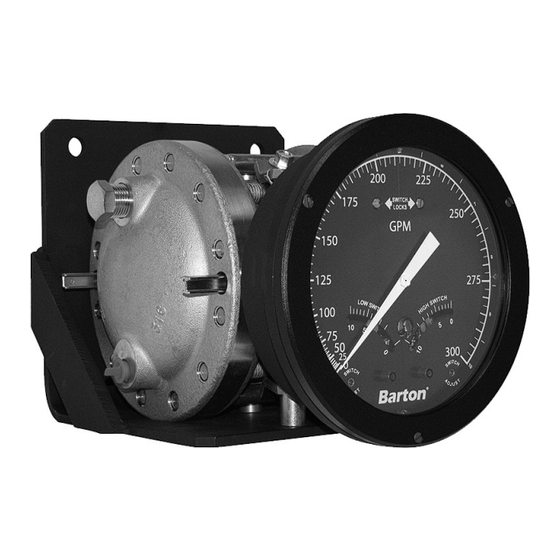
Model 289A Differential Pressure Indicating Switch Section 1 Section 1—Introduction General The weatherproof Model 289A is a differential pressure indicating switch. The Model 289A has a NEMA-4 watertight die-cast aluminum case (finished with a weather-resistant black epoxy resin paint). The cover lens is secured in the bezel with an elastomer ring to reduce the possibility of accidental break- age. -
Page 4: Indicating Switch
Section 1 Model 289A Differential Pressure Indicating Switch Indicating Switch (refer to Figure 1.2, Figures 2.1 to 2.6, and Table 2.1) Rotation of the DPU torque tube shaft is coupled through connecting linkage within the switch case to move the pointer across the scale plate. An actuat- ing cam, directly connected to the torque tube shaft, rotates with the motion of the shaft. -
Page 5: Relays
Model 289A Differential Pressure Indicating Switch Section 1 Standard models can have one or two alarm switches. Each switch can be connected to operate normally-opened or normally-closed. The direct-set switch contacts are adjustable over a scale range of 5-95% nominal for SPDT switches and 6-94% for DPDT switches. -
Page 6: Nuclear Qualifications
DPDT ..........±6% of full scale DP (max) Accuracy of Repeatability ....±0.25% of full scale DP Nuclear Qualifications The following nuclear qualification applications are based on Cameron Engineering Report 9A-CR3-288A-13 with switch chatter sensitivity addressed in Cameron Engineer- ing Report 9A-CR3-288A-19: •... -
Page 7: Section 2-Installation
Model 289A Differential Pressure Indicating Switch Section 2 Section 2—Installation General The instrument should be inspected at time of unpacking to detect any dam- age that may have occurred during shipment. IMPORTANT: The DPU was checked for accuracy at the factory. Do not change any of the settings during examination or accuracy could be affected. -
Page 8: Startup
Section 2 Model 289A Differential Pressure Indicating Switch IMPORTANT: Due to their size, subminiature switches have small mechanical clear- ances; therefore, no rating above 250 VAC has been established. Table 2.1—Switch/Relay Wire Color Coding (4/06c) 289A LEGACY CONFIGURATIONS 289A CURRENT CONFIGURATIONS (prior to Apr. 2006) SPDT SWITCHES Yellow Blue Yellow Blue... -
Page 9: Switch And Relay Wiring Diagrams
Model 289A Differential Pressure Indicating Switch Section 2 Switch and Relay Wiring Diagrams IMPORTANT: Figures 2.1 through 2.6 show: switch & relay contacts in the relaxed (shelf) condition, the low switch set to trip at a position below the pointer scale position, and the high switch set to trip at a position above the pointer scale position. - Page 10 Section 2 Model 289A Differential Pressure Indicating Switch LOW DPDT SWITCH HIGH DPDT SWITCH NO C NC NO C NC LOW & HIGH DPDT SWITCHES NO C NC NO C NC 10 11 12 Figure 2.2—Low/high DPDT switch diagrams (current configuration color codes - see Table 2.1, page...
- Page 11 Model 289A Differential Pressure Indicating Switch Section 2 3-SWITCHES 3-SWITCHES SPDT LOW & DPDT HIGH DPDT LOW & SPDT HIGH C NC NO C NC NO C NC Figure 2.3—3-switch diagram (current configuration color codes - see Table 2.1, page 4-SWITCHES INDEPENDENTLY ADJUSTABLE NO C NC...
- Page 12 Section 2 Model 289A Differential Pressure Indicating Switch LOW SWITCH HIGH SWITCH WITH SPDT RELAY WITH SPDT RELAY BLUE ORANGE YELLOW VIOLET BLACK WHITE/BROWN WHITE/GRAY WHITE/BROWN WHITE/GRAY 9 10 LOW & HIGH SWITCHES WITH SPDT RELAYS WIRE NUT (TYPICAL) BLUE ORANGE YELLOW VIOLET...
- Page 13 Model 289A Differential Pressure Indicating Switch Section 2 LOW SWITCH HIGH SWITCH WITH DPDT RELAY WITH DPDT RELAY WHITE/BLACK WHITE/RED NO C NC WHITE/VIOLET WHITE/YELLOW WHITE/ORANGE WHITE/BLUE ORANGE BLUE VIOLET YELLOW BLACK WHITE/GRAY WHITE/BROWN WHITE/GRAY WHITE/BROWN 9 10 LOW & HIGH SWITCHES WITH DPDT RELAYS WHITE/BLACK WHITE/RED...
-
Page 14: Section 3-Maintenance And Calibration
Section 3 Model 289A Differential Pressure Indicating Switch Section 3—Maintenance and Calibration The following checks are recommended for preventive maintenance: • Periodically inspect alarm switch mechanism to verify that all mounting screws are seated properly. • Inspect linkage for wear. •... -
Page 15: Calibration Check
Model 289A Differential Pressure Indicating Switch Section 3 Bezel (9A-C0277-0029C) Cover (Lens) (9A-C0181-0038C) Gasket (9A-C0277-0026C) Case Figure 3.1—Bezel and lens cover IMPORTANT: Ensure the bezel gasket is properly oriented before placing the instru- ment back in service. Incorrect gasket orientation will cause the instru- ment indicator to jam, resulting in inaccurate readings. -
Page 16: Pointer Installation And Removal
Section 3 Model 289A Differential Pressure Indicating Switch 3. To test for reverse travel, connect the pressure source to the LP housing and vent the HP housing. Apply pressures approximately 150% of the DP range. The pointer should move approximately 5% to 10% below zero. 4. -
Page 17: Indicator Calibration
Model 289A Differential Pressure Indicating Switch Section 3 2. Gently turn the knurled head of the screw clockwise, pushing the pin against the movement shaft and lifting the pointer with the arms. Finger pressure should be sufficient to pull the pointer free. If more pressure is required, an Allen wrench (inserted into head of the screw) can be used. - Page 18 Section 3 Model 289A Differential Pressure Indicating Switch 4. Check the pointer for zero indication. If necessary, set the pointer to zero by slipping the pointer on the hub, per Calibration Check, step 2, page 5. Apply 100% pressure. If the pointer exceeds full-scale, lengthen the movement range arm by adjusting the range adjust screw with a 1/8-in.
-
Page 19: Drive Arm Tightness Test
Model 289A Differential Pressure Indicating Switch Section 3 thumb, while holding the gear firmly in place. Retest the pointer response at 50%, 0%, and 100% of full-scale differential pressure, and adjust the linkage until the readings are acceptable. 10. Apply 0%, 25%, 50%, 75%, 100%, 75%, 50%, 25%, and 0% of full-scale differential pressure consecutively to the instrument without overshoot. -
Page 20: Drive Arm Stop Adjustment
Section 3 Model 289A Differential Pressure Indicating Switch Drive Arm Stop Adjustment 1. Apply sufficient pressure to the high-pressure housing to deflect the pointer against the full range stop snubber on the scale plate. 2. Slide the upper drive arm stop bracket against the drive arm and tighten the drive arm stop bracket screw. -
Page 21: Calibration Procedure
Model 289A Differential Pressure Indicating Switch Section 3 Advance the plunger screw until the switch actuates, then advance the plunger screw an additional 60° (one flat). Exercise the switch roller up and down the cam to verify consistent on/ off operation. Advance the stop screw to touch the switch, then back out the screw 1.5 turns (9 flats). -
Page 22: Changing Switch Set Point
Section 3 Model 289A Differential Pressure Indicating Switch If the switch is to be field-set at low differential pressure values (1% or 2% of pressure range), check the crank to prevent a top-dead-center posi- tion. Otherwise, the minimum set point position will be restricted and the set point may become reversed. -
Page 23: Changing Set Point Of An In-Service Instrument (Not Recommended For Nuclear Qualified Units)
Model 289A Differential Pressure Indicating Switch Section 3 itself. For example, the high switch (right side of scale) may be set at full scale, but should not be set near zero. The low switch may be set at zero, but should not be set near full scale. (Observe deadband values for specific models). -
Page 24: Changing Set Point Of An Out-Of-Service Instrument
Section 3 Model 289A Differential Pressure Indicating Switch IMPORTANT: The switch index has 10 divisions, marked 0, 5, and 10. These match the markings on the outer edge of the scale. Example: Scale has range of 0-60 psid. Set point is 24 psid, with decreasing pressure, (24/60 x 10 = 4). -
Page 25: Parts Repalcement
Model 289A Differential Pressure Indicating Switch Section 3 Parts Replacement Due to the new snap-acting microswitch being used in Model 289A differen- tial pressure indicating switch, the Drive Arm and Switch & Plate Assemblies have been redesigned. These assemblies are not backwards compatible and have to be installed at the same time for proper operation of the Model 289A. -
Page 26: Troubleshooting
Section 3 Model 289A Differential Pressure Indicating Switch Troubleshooting For troubleshooting tips, see Table 3.2 below. For information related to the DPU, see the Model 199 DPU user manual in Appendix A. Table 3.2—Troubleshooting Problem Possible Probable Cause Corrective Source Action Low or No Primary Orifice installed backwards or over-... - Page 27 Model 289A Differential Pressure Indicating Switch Section 3 Table 3.2—Troubleshooting Problem Possible Probable Cause Corrective Source Action High Primary Orifice partially restricted or too small Clean out or Indication Source replace Primary Piping leaks on LP side Repair leaks Element to DPU piping Bellows Gas (liquid service) or liquid (gas ser-...
- Page 28 Section 3 Model 289A Differential Pressure Indicating Switch Table 3.2—Troubleshooting Problem Possible Probable Cause Corrective Source Action Switch Process Transients or surges cause switches to Add time delay Drifts Changes actuate prematurely gages or add time (set circuit point not Set point and/or deadband are too Specify DP range repeat- wide in pressure valves...
-
Page 29: Section 4-Assembly Drawing And Parts Lists
Section 4 Model 289A Differential Pressure Indicating Switch Section 4—Assembly Drawing and Parts Lists... - Page 30 Section 4 Model 289A Differential Pressure Indicating Switch Table 4.1—Parts List, Model 289A Indicating Switch Item Description Part No. Per Unit Differential Pressure Unit (not shown) See Model 199 DPU User Manual in Appendix A Case Assembly 1/2 NPT Conduit, 1 & 2 Switches 9A-C0289-0003B 3/4 NPT Conduit, 1 & 2 Switches 9A-CS666-0051Z 1/2 NPT Conduit, 3 &...
- Page 31 Model 289A Differential Pressure Indicating Switch Section 4 Table 4.1—Parts List, Model 289A Indicating Switch Item Description Part No. Per Unit Screw, Flat, Skt Cap, 1/4-20 x 5/8, SST (Case 9A-C0240-0009J to DPU bracket) Gasket, Torque Tube 9A-C0199-0209C Stud, Drive-Lok, Retaining, Bezel 9A-C0004-0005K Screw, Relay Mtg. Hole Filler (if relay is not 9A-C0111-0007J installed, 2 per relay, not shown) Ground Wire Assembly, External Wire...
- Page 32 Section 4 Model 289A Differential Pressure Indicating Switch Table 4.1—Parts List, Model 289A Indicating Switch Item Description Part No. Per Unit Low Switch, Switch Adjustment Index Assy 9A-C0288-0028B High Alarm, Drive Plate Assembly 9A-C0288-0027B High Switch, Switch Adjustment Index Assy 9A-C0288-0029B Washer, Spring (1 per switch) 9A-C0257-0019C Screw, Lock (1 per switch) Switch #1 and #2...
- Page 33 Model 289A Differential Pressure Indicating Switch Section 4 Table 4.1—Parts List, Model 289A Indicating Switch Item Description Part No. Per Unit Tape Seal Patches 9A-CIT10-1045G Low Relay Assy (not shown) (with Tefzel insulated wires) Coil Voltage Wired SPDT Wired DPDT 115 VAC 9A-CS666-0238Z 9A-CS666-0245B 110 VDC 9A-CS666-0231Z 9A-CS666-0256B High Relay Assy (not shown)
- Page 34 Section 4 Model 289A Differential Pressure Indicating Switch Table 4.2—Tefzel Insulation (Radiation Resistant) External Wire Leads (Table 4.1, Items 27 and 28) Wire Type 2.5 ft 10 ft 15 ft 20 ft Low #1 9A-CS666-0213Z 9A-CS666-0190Z 9A-CS666-0194Z 9A-CS666-0201Z High #1 9A-CS666-0140Z 9A-CS666-0191Z 9A-CS666-0195Z 9A-CS666-0202Z Low #2 9A-CS666-0166Z 9A-CS666-0241Z 9A-CS666-0268B 9A-CS666-0203Z High #2 9A-CS666-0167Z 9A-CS666-0242Z 9A-CS666-0269B 9A-CS666-0204Z Low Relay 9A-CS594-0137Z...
-
Page 35: Section 5-Installation/Dimensional Drawings
Model 289A Differential Pressure Indicating SwitchSection 5 Section 5—Installation/Dimensional Drawings IMPORTANT: For DPU dimensional information, refer to the Model 199 DPU user manual in Appendix A. Figure 5.1—Model 289A, front view Table 5.1—Model 289A Dimensions (see Figures 5.2 and 5.3, page 36) PRESSURE HOUSING PRESSURE DIM. A DIM. B DIM. - Page 36 Section 5 Model 289A Differential Pressure Indicating Switch Figure 5.2—Model 289A, side view; see Table 5.1, page 35 for dimensions A, C and D Figure 5.3—Model 289A, rear view; see Table 5.1, page 35 for dimension B IMPORTANT: Model 289A version configurations are limited to nuclear applications; also refer to the Model 199 DPU user manual in Appendix A.
- Page 37 Cameron agrees to repair or furnish a replacement for, but not install, any product which within one (1) year from the date of shipment by Cameron shall, upon test and examina- tion by Cameron, prove defective within the above warranty.
- Page 38 APPENDIX A BARTON NUCLEAR MODEL 199 ® DIFFERENTIAL PRESSURE UNIT (DPU) User Manual Part No. 9A-C10034, Rev. 03 November 2018 Contents Technical Support ..................A-2 Section 1—Introduction ................A-3 General ......................A-3 Product Description..................A-3 Specifications .....................A-4 Section 2—Theory of Operation ..............A-5 Basic Components ..................A-5 Pressure Housings..................A-5 Bellows.......................A-5 Range Springs ...................A-7...
-
Page 39: Technical Support
Barton is a registered trademark of Cameron. © 2012 Cameron International Corporation (“Cameron”). All information contained in this publication is confidential and proprietary property of Cameron. Any reproduction or use of these instructions, drawings, or photographs without the express written permission of an officer of Cameron is forbidden. -
Page 40: Section 1-Introduction
Model 199 Differential Pressure Unit (DPU) Section 1 Section 1—Introduction General The Barton Model 199 Differential Pressure Unit (DPU) (see Figure 1.1) is ® a mechanical device which accurately measures differential pressure relative to a gas or liquid flowing through a process system, or to the level of a liquid contained in a process vessel. -
Page 41: Specifications
Section 1 Model 199 Differential Pressure Unit (DPU) Specifications Housing Material......Forged 316 Stainless Steel Torque Tube Rotation (full scale DP) 8° ±10% Torque Tube Material ...... Beryllium Copper (BeCu) Temperature Limits ......-40°F (-40°C) to +180°F (+82°C) Maximum Non-linearity: ....0-10"... -
Page 42: Section 2-Theory Of Operation
Model 199 Differential Pressure Unit (DPU) Section 1 Section 2—Theory of Operation Basic Components Torque Tube Center Plate Shaft Low Pressure Bellows Torque Tube Range Spring High Pressure Bellows High Pressure Low Pressure Overrange Housing Valve Temperature Compensator Low Pressure HP Housing Overrange Valve... - Page 43 Section 2 Model 199 Differential Pressure Unit (DPU) The DPU has two bellows. One end of each bellows is sealed. The open end of each bellows is attached and sealed to a side of the center plate (one bel- lows on each side) as shown in Figure 2.2. The bellows and center plate are filled with fill liquid via the drive arm hole plug.
-
Page 44: Range Springs
Model 199 Differential Pressure Unit (DPU) Section 2 Range Springs The range of the dual-bellows type DPU is determined by the force required to move the bellows through their normal range of travel. The range springs, which are available in various ranges (see Table 1.1, page A-4), act with the bellows and torque tube to balance the differential pressure ap- plied to the unit. -
Page 45: Pulsation Dampener
Section 2 Model 199 Differential Pressure Unit (DPU) Pulsation Dampener The pulsation dampener (Figure 2.1, page A-5) controls the flow of fill-liquid between the high and low-pressure bellows with an externally adjustable pul- sation dampener needle valve. Restriction of liquid flow reduces the effects of pulsation. -
Page 46: Section 3-Installation/Operation
Model 199 Differential Pressure Unit (DPU) Section 3 Section 3—Installation/Operation Unpacking The 199 DPU should be inspected at time of unpacking to detect any damage that may have occurred during shipment. IMPORTANT: The instrument was checked for accuracy at the factory. Do not change any of the settings during examination or accuracy will be affected. -
Page 47: Flow Applications
Section 3 Model 199 Differential Pressure Unit (DPU) 5. Install a suitable pulsation dampening device upstream of the DPU. Where severe pulsation is present, the accuracy of the flow measurement will be affected. 6. Mount the DPU on a solid support to minimize vibration. Tighten all points, using a suitable compound;... -
Page 48: Piping Diagrams
Model 199 Differential Pressure Unit (DPU) Section 3 Piping Diagrams Diagrams for typical and special flow applications are presented on the fol- lowing pages. Use the diagram best suited for the application as a guide for piping configuration. BYPASS VALVES SHUT-OFF STATIC PRESSURE VALVES... - Page 49 Section 3 Model 199 Differential Pressure Unit (DPU) VENT BYPASS VALVE VALVES STATIC PRESSURE CONNECTION (USE ONLY ONE) SHUT-OFF VALVES DRIP POTS BLOCK VALVES PRIMARY DEVICE Figure 3.3—Gas Flow, Hydrates Present PRIMARY DEVICE PLUGS BLOCK VALVES CONDENSING RESERVOIR SHUT-OFF VALVES VENT VALVES (OPTIONAL)
- Page 50 Model 199 Differential Pressure Unit (DPU) Section 3 PRIMARY DEVICE FILL TEE AND VENT VALVE FOR HOT OR GASSY LIQUIDS BLOCK VALVES SHUT-OFF VALVES BYPASS VALVE Figure 3.6—Liquid Flow, DPU Below Run BYPASS VALVE SHUT-OFF SEAL VALVES POTS PRIMARY DEVICE BLOCK VALVES Figure 3.7—Corrosive Liquid Flow...
- Page 51 Section 3 Model 199 Differential Pressure Unit (DPU) BLOCK VALVE SHUT-OFF VALVE BLOCK VALVE SHUT-OFF VALVE DRAIN VALVE HIGH-PRESSURE Figure 3.9—Cool Non-Condensing Liquid, DPU Below Tank 2" CROSS BLOCK REFERENCE VALVE VENT SHUT-OFF VALVE VALVE BLOCK VALVE SHUT-OFF HIGH-PRESSURE VALVE BYPASS DRAIN VALVE VALVE...
- Page 52 Model 199 Differential Pressure Unit (DPU) Section 3 BLOCK VALVE INVERTED "U" GAS TRAP BLOCK VALVE MINIMUM LENGTH DRAIN 6 INCHES SHUT-OFF VALVE VALVE VAPOR GENERATOR LOW-PRESSURE Figure 3.11—Liquid CO2 BLOCK VALVE MINIMUM LENGTH 12 INCHES INVERTED "U" GAS TRAP VAPOR GENERATOR FLAT TUBULAR SPIRAL IN OUTER 1/3 OF TANK...
- Page 53 Section 3 Model 199 Differential Pressure Unit (DPU) SIGHT FLOW GAGE BLOCK VALVES INPUT GAS REGULATOR SUPPLY SHUT-OFF VALVES BYPASS VALVE HIGH PRESSURE Figure 3.13—Bubbler System SIGHT FLOW GAGES WITH THROTTLING VALVES INPUT GAS REGULATOR BLOCK VALVES SHUT-OFF VALVES SUPPLY BYPASS VALVE HIGH-PRESSURE Figure 3.14—Liquid Specific Gravity...
-
Page 54: General Startup Practice Considerations
Model 199 Differential Pressure Unit (DPU) Section 3 General Startup Practice Considerations Observe the following practices when starting up an instrument. 1. Always start with the block valves closed. 2. Perform a zero check on the instrument as follows. IMPORTANT: For gas service, it is recommended that zero check be performed with both block valves closed. -
Page 55: Section 4-Maintenance, Adjustment, & Calibration
Section 4—Maintenance, Adjustment, & Calibration Tools Required for Maintenance and Calibration Cameron's calibration tool kit (Part No. 9A-0202-1005B) contains the tools necessary for calibrating the Model 199 DPU. The tools listed in Table 4.1 are also recommended for performing general maintenance. -
Page 56: Inspection And Cleaning Procedure
Model 199 Differential Pressure Unit (DPU) Section 4 Inspection and Cleaning Procedure Instruments used in services where solids or semi-solids may accumulate inside the pressure housings require periodic inspection and cleaning, as fol- lows. 1. Remove the DPU from service and remove the pressure housings. 2. -
Page 57: Calibration Setup
Section 4 Model 199 Differential Pressure Unit (DPU) Calibration Setup The test equipment required to calibrate the Model 199 DPU, when attached to an indicator or switch is shown in Figure 4.1. All Barton instruments using the Model 199 DPU as actuator are calibrated at the factory. -
Page 58: Torque Tube Rotation Check (Replacement Units
Model 199 Differential Pressure Unit (DPU) Section 4 Torque Tube Rotation Check (Replacement Units) Prior to installation as a replacement unit, a DPU should be checked for proper torque tube rotation, per the following procedure: 1. Mount DPU on a stable base and connect to a standard pressure source. 2. -
Page 59: 3-3/4-Inch Diameter Bellows Without Kickoff Spring (>47" W.c
Section 4 Model 199 Differential Pressure Unit (DPU) 4. Install the new range spring assembly onto the push rod, and replace the spring retainer screw. 5. If the pointer is set above zero, rotate the spring adjustment clockwise until the pointer is set at zero. If the pointer is below zero, rotate the spring adjustment counterclockwise until the pointer is set at zero. -
Page 60: 3-3/4-Inch Diameter Bellows With Kickoff Spring
Model 199 Differential Pressure Unit (DPU) Section 4 3-3/4-inch Diameter Bellows with Kickoff Spring The kickoff spring (also referred to as the "anti-stick" spring) is supplied as standard equipment with 46" w.c. and lower range DPUs. Figure 4.2—Kickoff spring assembly IMPORTANT: The lock nut requires a modified 7/16", 12-point box wrench for tighten- ing (Figure 4.3). - Page 61 Section 4 Model 199 Differential Pressure Unit (DPU) 4. Install the range spring assembly, using a 1/2-inch open-ended wrench to connect the push rod to the low-pressure bellows cup. IMPORTANT: The range spring assembly consists of the range springs, kickoff spring assembly, and the push rod.
-
Page 62: Setting Bellows Travel
Model 199 Differential Pressure Unit (DPU) Section 4 Setting Bellows Travel The travel of the DPU bellows must be adjusted if one of the following oc- curs. 1. The range spring assembly is removed without following the procedure. 2. Broken range springs are replaced. 3. -
Page 63: Attaching Drive Arm To Torque Tube
Section 4 Model 199 Differential Pressure Unit (DPU) WARNING: Do not reuse housing bolts. Reuse of housing bolts, especial- ly in critical applications like hydrogen sulfide and salt water exposures, can result in severe injury, death or substantial property damage due to bolt failure. 7. Attach the indicator bracket to the replacement assembly, using the indi- cator bracket screws. -
Page 64: Drive Arm Tightness Test
Model 199 Differential Pressure Unit (DPU) Section 4 Drive Arm Tightness Test This procedure tests the tightness of the drive arm's connection to the torque tube by applying torque developed by the DPU onto a fixed drive arm. Care should be taken to apply pressure slowly, as torque is being applied to the connection through the torque tube drive shaft. - Page 65 Section 4 Model 199 Differential Pressure Unit (DPU) Table 4.3—Troubleshooting Chart Trouble Possible Source Probable Cause Corrective Action Low or No Primary Element Orifice installed backwards Replace orifice Indication or Differential or oversized Pressure Source Flow blocked upstream Clean out run or from run open valve Loss of liquid in reference...
- Page 66 Model 199 Differential Pressure Unit (DPU) Section 4 Table 4.3—Troubleshooting Chart Trouble Possible Source Probable Cause Corrective Action High Primary Orifice partially restricted Clean out or replace or too small Indication Piping from Leak in LP side piping Repair leaks Primary Element to DPU Bellows Unit...
-
Page 67: Section 5-Parts Drawing/List
Section 5 Model 199 Differential Pressure Unit Section 5—Parts Drawing/List Figure 5.1—Model 199 DPU parts drawing (indicator and indicator switch mounting brackets vary as shown; see 200A/289A and 581A insets) A-30... - Page 68 Model 199 Differential Pressure Unit Section 5 Table 5.1—Model 199 Parts List Item Description Part No. Unit BUA (BELLOWS UNIT ASSEMBLY) SELECT HOUSING, PRESSURE, TAPPED (MATCH PORTS WITH ITEM 3) HOUSING, 1 K SST, 1/4 X 1/4 NPT 9A-CS787-0071C HOUSING, 1 K SST, 1/4 X 1/2 NPT (TOP/BOTTOM) 9A-CS787-0061C HOUSING, 1 K SST, 1/2 X 1/4 NPT (TOP/BOTTOM) 9A-C0199-1038C...
- Page 69 Section 5 Model 199 Differential Pressure Unit Table 5.1—Model 199 Parts List Item Description Part No. Unit SCREW, FL HEX SOC CAP HD 3/8-16 X 7/8, ST - 9A-C0240-0003J MODEL 200A/289A SCREW, FL HEX SOC CAP HD 3/8-16 X 1 - 9A-C0240-0004J MODEL 581A TAG, S/N, DPU MTG BRK - MODEL 200A/289A...
- Page 70 Model 199 Differential Pressure Unit Section 5 Table 5.1—Model 199 Parts List Item Description Part No. Unit SPRING ASSY, INC, 23 - 27" WC 9A-C0199-1391B (cont.) SPRING ASSY, INC, 28 - 31" WC 9A-C0199-1395B SPRING ASSY, INC, 32 - 38" WC 9A-C0199-1397B SPRING ASSY, INC, 39 - 46"...
- Page 71 Section 5 Model 199 Differential Pressure Unit Table 5.1—Model 199 Parts List Item Description Part No. Unit SPRING ASSY, INC, 0 - 40 PSI 9A-C0199-1429B (cont.) SPRING ASSY, INC, 0 - 45 PSI 9A-C0199-1427B SPRING ASSY, INC, 0 - 50 PSI 9A-C0199-1423B SPRING ASSY, INC, 0 - 60 PSI 9A-C0199-1445B...
-
Page 72: Section 6-Dimensional Drawings
Model 199 Differential Pressure Unit (DPU) Section 6 Section 6—Dimensional Drawings Figure 6.1—Dimensional drawing, Model 199 DPU, rear view Figure 6.2—Dimensional drawing, Model 199 DPU, side view A-35... - Page 73 Section 6 Model 199 Differential Pressure Unit (DPU) Table 6.1—Model 199 DPU Dimensions Pressure Rating Dim. A Dim. B Dim. C # Bolts psi (bar) inches (mm) inches (mm) inches (mm) 1,000 (69) 6-5/8 (168.3) 2 (50.8) 2-9/64 (54.4) 3,000 (207) Ø...
- Page 74 If any defect within this warranty appears, Buyer shall notify Cameron immediately Cameron agrees to repair or furnish a replacement for, but not install, any product which within one (1) year from the date of shipment by Cameron shall, upon test and examination by Cameron, prove defective within the above warranty.
- Page 75 + 6 0 3 . 5 5 6 9 . 0 5 0 1 ms-kl@c-a-m.com R U S S I A...
Need help?
Do you have a question about the BARTON 289A and is the answer not in the manual?
Questions and answers