Cameron 351 Installation Manual

Cameron 351 Installation Manual

Barton nuclear liquid level systems

Advertisement

Contents
Safety ............................................................................................................... 2
Section 1- Introduction ................................................................................ 3
General ......................................................................................................... 3
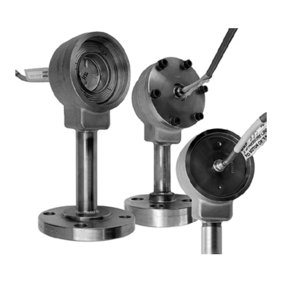
Product Description....................................................................................... 4
Model 351 Liquid Level System ................................................................ 4
Model 352 Liquid Level System ................................................................ 4
Model 351/352 System Sensors ............................................................... 4
Model 353 Liquid Level System ................................................................ 5
Sensor Housings and Capillary Tubing ......................................................... 5
Specifications ................................................................................................ 6
Section 2-Theory of Operation .................................................................... 7
General ......................................................................................................... 7
Model 353 Sensor ..................................................................................... 7
Section 3-Installation ................................................................................... 9
Unpacking ..................................................................................................... 9
Model 353 Sensor Assembly ..................................................................... 9
Mounting ....................................................................................................... 9
Piping and Installation ................................................................................... 9
Section 4-Operation, Maintenance, and Calibration ............................... 13
Startup ........................................................................................................ 13
General Field and Periodic Maintenance .................................................... 13
Model 351 Sensor Inspection and Cleaning............................................ 13
Model 353 Sensor Inspection and Cleaning ........................................... 13
Model 353 Sensor Bellows Removal/Replacement .................................... 14
Calibration ................................................................................................... 16
Troubleshooting .......................................................................................... 16
Section 5-Parts List.................................................................................... 17
General ....................................................................................................... 17
Section 6-Dimensional Drawings ............................................................. 27
General ....................................................................................................... 27
Product Warranty ........................................................................................ 33
Product Brand ............................................................................................. 33
BARTON
MODELS 351/352/353
LIQUID LEVEL SYSTEMS
Installation Manual
Part No. 9A-C10521, Rev. 03
NUCLEAR
®
November 2015

Advertisement

Table of Contents
loading
Need help?

Need help?

Do you have a question about the 351 and is the answer not in the manual?

Questions and answers

Summary of Contents for Cameron 351

  • Page 1: Table Of Contents

    Safety ....................... 2 Section 1— Introduction ................3 General ......................3 Product Description..................4 Model 351 Liquid Level System ..............4 Model 352 Liquid Level System ..............4 Model 351/352 System Sensors ............... 4 Model 353 Liquid Level System ..............5 Sensor Housings and Capillary Tubing ............
  • Page 2: Safety

    Safety Before installing this product, become familiar with the installation instruc- tions presented in Section 3. In addition, adhere to the following safety precautions: Pressure – The instrument shall not be subjected to pressure higher than the safe working pressure stamped on the pressure housings. Corrosion –...
  • Page 3: Section 1- Introduction

    Sealed sensor systems can be designed in the following configurations: • a single sensor system (Model 351) • a dual-sensor system (Model 352) For applications involving corrosive fluids or tank temperatures above 200°F (95°C), a dual-sensor configuration is recommended.
  • Page 4: Product Description

    The Model 351 system, as shipped from the factory, needs only to be mount- ed on the vessel to provide continuous level measurement when used with a Barton readout instrument.
  • Page 5: Model 353 Liquid Level System

    Model 351/352/353 Liquid Level Systems Section 1 The S048 sensor is constructed with the same housing as the 500-psi SWP sen- sor for mounting purposes, but has no pressure rating and is designed to mount inside open ves sels or sumps. The large bottom opening of the sensor prevents fouling of the sensor ports due to dirt, loose debris, or other contamination.
  • Page 6: Specifications

    Section 1 Model 351/352/353 Liquid Level Systems Specifications Specifications for Barton sealed sensor systems are presented in Tables 1.1 and 1.2. CAUTION: Never operate the system at pressures exceeding the safe working pressure of the sensor flange or attached instrument, whichever is lower. Periodic testing at pressures up to 150% of the safe working pressure is permitted, provided the pressure is applied equally and simultaneously to the entire system.
  • Page 7: Section 2-Theory Of Operation

    DPU. Model 351/Model S048 Sensors The pressure deflection characteristics of the Model 351 (500-psi or 3,000- psi) and Model S048 sensor bellows are shown in Figure 2.1. Figure 2.1—Pressure deflection characteristics of the Model 351/352 sensor bellows...
  • Page 8 Section 2 Model 351/352/353 Liquid Level Systems then closes an internal valve to prevent further loss of bel lows liquid. This action prevents escape of process liquid. The sensor bellows may be removed with a special wrench (see Table 4.1 and Figure 4.1,...
  • Page 9: Section 3-Installation

    Model 351/352/353 Liquid Level Systems Section 3 Section 3—Installation Unpacking All instruments are inspected during manufacture and prior to shipping. How- ever, an inspection should be performed at the time of unpacking to detect any damage that may have occurred during shipping.
  • Page 10 Section 3 Model 351/352/353 Liquid Level Systems Capillary Tubing Welding Figures 3.1 through 3.3 present the information and procedures necessary to weld the capillary tubing and tubing coupling. Figure 3.1—1/4-in. OD capillary tubing welds IMPORTANT: All parts are solution annealed 316 or 304 stainless steel. Please adhere to the following welding practices: (1) Weld type: GTAW fillet, 45 amps, 10 volts, 20 CFH (9.5 l/m) Argon...
  • Page 11 Model 351/352/353 Liquid Level Systems Section 3 Figure 3.2—3/16-in. OD capillary tubing welds IMPORTANT: All parts are solution annealed 304L stainless steel. Please adhere to the following welding practices: (1) Weld type: GTAW fillet, 45 amps, 10 volts, 20 CFH (9.5 l/m) Argon gas flow.
  • Page 12 Section 3 Model 351/352/353 Liquid Level Systems Figure 3.3—3/16-in. OD capillary tubing coupling welds IMPORTANT: All parts are solution annealed 304L stainless steel. Please adhere to the following welding practices: (1) Weld type: GTAW V-groove, 45 amps, 10 volts, 20 CFH (9.5 l/m) Argon gas flow.
  • Page 13: Section 4-Operation, Maintenance, And Calibration

    When removing the sensor assembly, avoid unnecessary contact with the housing. Model 351 Sensor Inspection and Cleaning Remove the sensor from the housing. The 500 psi (3.5 MPa) sensor is connected by a retainer ring; the 3000 psi (20.7 MPa) sensor is connected by 6 bolts.
  • Page 14: Model 353 Sensor Bellows Removal/Replacement

    Section 3 Model 351/352/353 Liquid Level Systems Model 353 Sensor Bellows Removal/Replacement The sensor bellows must be removed under the following circumstances: • when the capillary system is to be pressurized • for argon flow during weld ing • for static pressure tests of the capillary system •...
  • Page 15 Model 351/352/353 Liquid Level Systems Section 4 Figure 4.2—Model 353 sensor bellows and bottom plate assembly To install the sensor bellows, perform the following steps: Inspect the sensor bellows to verify that the bellows is undamaged and the guide stem is in place.
  • Page 16: Calibration

    Section 4 Model 351/352/353 Liquid Level Systems CAUTION: The sensor bellows can be damaged by contact with the housing. When installing the sensor assembly, avoid unnecessary contact with the housing. Calibration The actuated instrument is calibrated according to the procedure presented in the installation and operation manual for that instrument.
  • Page 17: Section 5-Parts List

    Component parts are called out in figures and listed by sensor type in the corresponding tables. Sensor Type Table Reference Model 351 Sensor, 500 psi (3.5 MPa) page 18 Model 351 Sensor, 3000 psi (20.7 MPa) page 20 Model S048 Sensor...
  • Page 18 Section 4 Model 351/352/353 Liquid Level Systems NOTE: Mounting bracket No. 9 may be reversed or rotated to obtain the desired configuration. Table 5.1—Model 351 Sensor Assembly 500 psi (3.5 MPa) Item Description Part No. Qty per System** O-ring 9A-C0001-1074R...
  • Page 19 1” Class 150, FF/SO, 316 SST 9A-CS696-0375C 2:1 Class 150, FF/SO, 316 SST 9A-CS696-0363T Nut, Lock, SST 9A-C0353-1013C *Recommended Spare Parts (EPT = Ethylene Propylene Terpolymer) ** Model 351 systems have a single sensor; Model 352 systems require two sensors.
  • Page 20 Section 5 Model 351/352/353 Liquid Level Systems NOTE: Mounting bracket No. 9 may be reversed or rotated to obtain the desired configuration. Table 5.2—Model 351 Sensor Assembly 3000 psi (20.7 MPa) Item Description Part No. Qty/System** O-ring 9A-C0001-1074R Viton 9A-C0001-0131R...
  • Page 21 2:1 Class 600, RF/SO, 316 SST 9A-CS696-0133Z 2:1 Class 1500, RF/SO, 316 SST 9A-CS696-0115Z Nut, Lock, SST 9A-C0353-1013C *Recommended Spare Parts (EPT = Ethylene Propylene Terpolymer) ** Model 351 systems have a single sensor; Model 352 systems require two sensors.
  • Page 22 Section 5 Model 351/352/353 Liquid Level Systems NOTE: Mounting bracket No. 7 may be reversed or rotated to obtain the desired configuration. Table 5.3—Model S048 Sensor Assembly Item Description Part No. Qty/System** Sensor Housing, SST 1” NPT (L-bracket mounting) 9A-CS048-0007Z 1”...
  • Page 23 (not shown) 1” Class 150, FF/SO, 316 SST 9A-CS696-0375C 2:1 Class 150, FF/SO, 316 SST 9A-CS696-0363T * Recommended Spare Parts (EPT = Ethylene Propylene Terpolymer) ** Model 351 systems have a single sensor; Model 352 systems require two sensors.
  • Page 24 Section 5 Model 351/352/353 Liquid Level Systems 0.192/0.197 in. (4.9/5.0 mm) ID NOTE: Mounting bracket No. 7 may be reversed or rotated to obtain the desired configuration. Table 5.4—Model 353 Sensor Assembly Item Description Part No. Sensor Housing, SST 9A-C0353-1133B...
  • Page 25 Model 351/352/353 Liquid Level Systems Section 5 Table 5.4—Model 353 Sensor Assembly Item Description Part No. Fill Valve & Tee Assembly (See Figure 5-5) 9A-C0351-1044B Lubricant, O-ring (not shown) 9A-C0002-1003U As Required Process Connection Adapter 3/8” Tube 9A-C0353-1010C 1/2” Tube 9A-C0353-1009C 3/4”...
  • Page 26 Section 5 Model 351/352/353 Liquid Level Systems Table 5.5—Fill Valve Assembly (Part of Fill Valve & Tee Assembly, Part No. 9A-C0351-1044B) Item Description Part No. Qty/Unit Valve Body Assembly 9A-C0353-1014B Valve 9A-C0353-1011C O-ring, Backup, EPT, #8-006 9A-C0001-1062R O-ring, EPT, #2-006...
  • Page 27: Section 6-Dimensional Drawings

    The drawings in this section show the outline dimensions for each sensor as- sembly. These images are based on production drawing 9A-C0351-10782. Liquid Level System Type Figure Reference Model 351, 500 psi (3.5 MPa) page 28 Model 351, 3000 psi (20.7 MPa) page 29 Model S048 page 30 Model 353, 3000 psi (20.7 MPa)
  • Page 28 Section 5 Model 351/352/353 Liquid Level Systems Figure 6.1—Model 351 sensor, 500 psi (3.5 Mpa)
  • Page 29 Model 351/352/353 Liquid Level Systems Section 6 Figure 6.2—Model 351 sensor, 3000 psi (20.7 MPa)
  • Page 30 Section 6 Model 351/352/353 Liquid Level Systems Figure 6.3—Model S048 sensor...
  • Page 31 Model 351/352/353 Liquid Level Systems Section 6 Figure 6.4—Model 353 sensor, 3000 psi (20.7 MPa)
  • Page 32 Section 6 Model 351/352/353 Liquid Level Systems...
  • Page 33: Product Warranty

    If any defect within this warranty appears, Buyer shall notify Cameron immediately Cameron agrees to repair or furnish a replacement for, but not install, any product which within one (1) year from the date of shipment by Cameron shall, upon test and examination by Cameron, prove defective within the above warranty.
  • Page 34 Section 6 Model 351/352/353 Liquid Level Systems...
  • Page 36 HEADQUARTERS (HOUSTON, TX) UNITED STATES CANADA 1.281.582.9500 1.800.654-3760 1.403.291.4814 ms-us@c-a-m.com ms-canada@c-a-m.com INDIA LATIN AMERICA ASIA PACIFIC 91.982.2431686 +55.21.2172.9714 +603.7954.0145 ms-ind@c-a-m.com ms-latinamerica@c-a-m.com ms-kl@c-a-m.com MIDDLE EAST & NORTH AFRICA EUROPE, CASPIAN, RUSSIA & S. AFRICA 971.4802.7700 +44.1892.518000 ms-me@c-a-m.com ms-uk@c-a-m.com w w w . c - a - m . c o m / m e a s u r e m e n t...

This manual is also suitable for:

352353

Table of Contents