Table of Contents
Advertisement
Quick Links
Advertisement
Table of Contents

Related Manuals for Cameron NUFLO 1141C


Summary of Contents for Cameron NUFLO 1141C
- Page 1 NUFLO Scanner 1141 RTU Hardware User Manual Manual No. 30165009, Rev. 01...
- Page 2 Acrobat Reader is a registered trademark of Adobe Systems Incorporated. © 2007 Cameron International Corporation (“Cameron”). All information contained in this publication is confidential and proprietary property of Cameron. Any reproduction or use of these instructions, drawings, or photographs without the express written permission of an officer of Cameron is forbidden.
- Page 3 The products are intended to be used in accordance with the specification and applications described in this document. A limited warranty applies to products manufactured by Cameron’s Measurement Systems Division. The Company will assume responsibilities for obligations, related to its products, which are specifically noted within the written warranty for a specific product.
- Page 4 Product Warranty Statement The warranty applicable to this product is stated at the beginning of this manual. Should any problem arise after delivery, contact Cameron’s Measurement Systems Division HelpDesk at 1-877-805-7226...
-
Page 5: Table Of Contents
Table of Contents TABLE OF CONTENTS CHAPTER 1: OVERVIEW AND SPECIFICATIONS..............9 ® Overview of the Scanner 1141 ........................9 Enclosures............................... 10 Standard Display ............................. 11 Autoscroll ..............................12 Scanner Software ............................13 Scanner Firmware ............................13 IGas ................................13 NGas................................13 NFlo ................................ - Page 6 Test Voltages ..............................63 NVRAM Lithium Battery Voltage........................64 NVRAM Battery Change Procedure......................64 Returning the Scanner to Cameron’s Measurement Systems Division............65 Replacing the Sealed Lead Acid Battery ......................65 CHAPTER 6: PARTS LIST AND ORDER CODE ............... 67 Scanner 1141C ...............................
- Page 7 Table of Contents MVT/RTD Input ............................81 RTD Element ............................... 82 RTD (Analog) Inputs ............................ 83 Analog Inputs ............................... 83 Pulse Inputs ..............................83 Discrete Inputs/Outputs ..........................85 Analog Output .............................. 85 Expansion Board Interface .......................... 86 Transmitter and Auxillary Power Supply...................... 86 Power Supply &...
- Page 8 Scanner 1141 Hardware User Manual Pulse Inputs............................... 109 I/O Termination ............................. 110 Configuration Switches ..........................111 Status Input/Output and Pulse Output Circuits ..................111 Serial Port Switches ..........................111 Pulse Input Switches ..........................111 Analog Output Switch..........................112 MIO2 Expansion Board Installation....................... 112 APPENDIX E: FLASHING THE SCANNER..............
-
Page 9: Chapter 1: Overview And Specifications
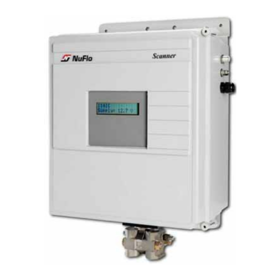
Chapter 1: Overview and Specifications Chapter : Overview and Specifications ® Overview of the Scanner 1141 ® The Scanner 1141 is an economical, single-stream or dual-stream measurement Remote Terminal Unit (RTU) with flow and pressure control capability. It offers a powerful alternative to chart recorders in gathering data for natural gas production and includes a full range of operator-selectable mass, energy, and volume algorithms. -
Page 10: Enclosures
Scanner 1141 Hardware User Manual The following features in the Scanner 1141 provide convenient and flexible operation: Configurable Memory - A full set of menu-selectable calculation options are stored in Flash memory in each Scanner 1141. As new industry standards are adopted, new programs are easily loaded from a PC with WinsLoad or ScanFLASH Utility software (See Appendix E: Flashing Scanner, page 113). -
Page 11: Standard Display
Chapter 1: Overview and Specifications Standard Display The standard display on the Scanner 1141 is a large 2-line × 16-character liquid crystal display (LCD) with optional backlighting. To save power, the display can be configured to shut off automatically after a user-specified time period (usually about 30 seconds). -
Page 12: Autoscroll
Scanner 1141 Hardware User Manual Figure 1.1—Display “wake-up” button Auto-scroll The display “auto-scrolls” through a list of user-definable readouts. Each item is held on the display for a configurable amount of time and is then replaced by the next item in the list. An operator can pause the auto-scroll on any displayed item by pressing the “wake-up”... -
Page 13: Scanner Software
Chapter 1: Overview and Specifications The display will shut off automatically after a configurable amount of time (usually about 30 seconds). To “wake-up” the display, press the “wake-up” button. Scanner Software ™ ScanWin Lite is a Windows -based software program for monitoring, configuring and downloading Scanner Measurement RTU data on-site. -
Page 14: Nflo
Scanner 1141 Hardware User Manual • An interpolation method • GERG Virial Equation for Field Use • Standard GERG Virial Equation NFlo NFLo performs the same calculations as NGas, plus liquid properties calculations based on the API Manual of Petroleum Measurement Standards (MPMS) chapters 11.2.1, 11.2.2, 11.2.3 and API 2540. -
Page 15: Chapter 2: Installation
(-40°F to +140°F). FOR ADDITIONAL INSTRUMENT SPECIFICATIONS, SEE APPENDIX A. Note: Circuit boards returned to Cameron’s Measurement Systems Division factory for repair must be properly packed for static protection. If they are not, the boards will not be covered by the Cameron warranty. -
Page 16: Securing The Enclosure
Scanner 1141 Hardware User Manual Securing the Enclosure Figures 2.1 through 2.4 show examples of materials that are appropriate for securing the 1141 enclosure for Class I, Division 2 installations so that a tool is required to gain access. A lock may also be used to secure the enclosure. - Page 17 Chapter 3: Main Circuit Board Wiring Figure 2.3—Seal wire installation on an 1141C latch (left) and an 1141L latch (right) Figure 2.4—Seal wire installation on an 1141C hinge (left) and an 1141L hinge (right)
-
Page 18: Unpacking The Scanner
Scanner 1141 Hardware User Manual The following chart outlines the sequence of steps required for installing the Scanner 1141 RTU: Table 2.1—Installation Summary Step Description Reference Section Unpacking the Scanner Page 18 Mounting the Scanner Page 199 Connecting the Scanner to piping Page 20 Connecting the power supply and charge controller Page 23... - Page 19 Chapter 3: Main Circuit Board Wiring Figure 2.5—Components of 1141C Figure 2.6—Components of 1141L...
-
Page 20: Mounting The Scanner
Scanner 1141 Hardware User Manual CAUTION MOUNT BATTERY TERMINALS TOWARD THE FRONT OF THE ENCLOSURE TO HELP PREVENT THE TERMINALS FROM CONTACTING THE INTERNAL METAL BRACKETS. CAUTION Mounting the Scanner A universal 2-in. bracket is used to mount the Scanner 1141C and 1141L to a wall or a pipe. The 1141G is surface-mounted using the four holes on the mounting plate. - Page 21 Chapter 3: Main Circuit Board Wiring Figure 2.7—Typical installation of Scanner 1141C/L with a radio or modem for Class I, Div. 2 installations (integral communications) Note: Solar panels must be installed in accordance with Div. 2 wiring methods, using TECK cable or conduit.
-
Page 22: Installing And Connecting A Solar Panel
Scanner 1141 Hardware User Manual Figure 2.8—Typical installation of Scanner 1141C/L with remote communications Installing and Connecting a Solar Panel Mount the solar panel on a post facing the equator, or mount it directly to a flat surface (see chart below for tilt angles). -
Page 23: Connecting The Power Supply / Charge Controller
Chapter 3: Main Circuit Board Wiring Tilt Angle Figure 2.9—Tilt angles to be observed when mounting the solar panel Note: Angles are marked on the bracket of the solar panel (0° - 90° tilt). Connecting the Power Supply / Charge Controller Power supply/solar panel wires enter the enclosure through the side or bottom conduit entry (Figures 2.5 and 2.6). - Page 24 Scanner 1141 Hardware User Manual The Scanner can be powered by a solar panel or a 6-28 VDC power supply (10 amps, max.). To connect power to the instrument, perform the following steps: 1. Wire the solar panel or power to the barrier terminal block in the back of the 1141 enclosure, connecting the red wire (+) to terminal 2 and the black wire (–) to terminal 3, as shown in Figure 2.8.
- Page 25 Chapter 3: Main Circuit Board Wiring Figure 2.11—Power supply type selection CAUTION BEFORE CONNECTING A 6V BATTERY, MAKE SURE THE UNIT IS CONFIGURED FOR A 6V BATTERY. IF THE UNIT IS CONFIGURED FOR A 12V BATTERY, CONNECTING A 6V BATTERY TO IT COULD OVERCHARGE THE BATTERY. TO PREVENT AN ELECTRICAL SHORT, BEFORE SUPPLYING POWER TO THE UNIT, MAKE SURE THE LEADS FROM CAUTION BATT + TERMINALS ARE NOT TOUCHING METAL OR EACH OTHER.
- Page 26 Scanner 1141 Hardware User Manual Figure 2.12—Label for identifying fast-blow fuse b. Connect the factory-installed black wire extending from the Batt- terminal (terminal 5) to the negative (-) terminal of the battery (Figure 2.13). Figure 2.13—Battery connections on the main circuit board Chapter 3: Main Circuit Board Wiring for additional wiring information.
-
Page 27: Chapter 3: Main Circuit Board Wiring
Chapter 3: Main Circuit Board Wiring Chapter : Main Circuit Board Wiring Major Components The main circuit board, located on the inside of the door on 1141C and 1141L models, contains all of the switches, jumpers, terminal blocks, and other connectors required for wiring the Scanner 1141 to a power supply, a charge controller, and communication devices, and for enabling the Scanner to utilize various input/outputs. - Page 28 Scanner 1141 Hardware User Manual Figure 3.1— Scanner 1141 main circuit board...
-
Page 29: Switches, Jumpers, And Potentiometers
Chapter 3: Main Circuit Board Wiring Switches, Jumpers, and Potentiometers Note: It is very IMPORTANT that the following jumper settings be observed: CN11 – “RAM Size” jumper; “High” is 96 kbytes, “Low” is 64 kbytes CN20 – “Backup Batt” jumper; position across upper pins to enable backup battery power for non volatile memory (NVRAM). - Page 30 Scanner 1141 Hardware User Manual CN20 Backup Battery Enables and disables the Position jumper across lithium backup battery power upper pins to enable lithium to the NVRAM backup battery; position jumper across bottom pins to disable lithium backup battery. Serial Port A02 RS-485 termination and Auxiliary Serial Ports,...
- Page 31 Chapter 3: Main Circuit Board Wiring Below is a detailed description of the functions of each of the switches shown in Table 3.1. Config Lock (SW11) The optional Configuration Lock switch (SW11) is legally required for custody transfer applications in some locations. When the Configuration Lock mechanism is installed, it is located beside the Power switch SW9.
- Page 32 Scanner 1141 Hardware User Manual Pwr (SW9) This switch performs a properly supervised system shutdown when placed in the OFF position. SW9 generates a power fail interrupt to the CPU and after a 10-ms delay, shuts the power off to the entire system board. Figure 3.3—...
- Page 33 Chapter 3: Main Circuit Board Wiring Figure 3.4— CN20 and CN21 connectors Backup Batt (CN20) Jumper CN20 (Figure 3.4) enables and disables the lithium backup battery power to the NVRAM. The Scanner 1141 is shipped with the battery jumper in the OFF position. Set the jumper to ON before configuring the flow computer and leave the jumper in the ON position when the Scanner 1141 is in operation.
- Page 34 Scanner 1141 Hardware User Manual For RS-232 communications, Resource A02 uses SW 6 and terminals 9 through 12; if these terminals are not present, the RS-232 option is not installed. Figure 3.5—Switches SW6, SW5, SW4 and SW3 Serial Port A21 (SW2) Auxiliary serial port A21 (shown in Figure 3.6) is one of two auxiliary serial ports (see also Serial Port A02) that can be can be software- configured to support either RS-485 or RS-232C communications, (refer to the ScanWin manual, Chapter 7: About the System).
- Page 35 Chapter 3: Main Circuit Board Wiring Figure 3.6— CN11 jumper, SW2, SW1, CN3, and FPGA Load jumper Pulse Input (SW5) SW5 is a six-position DIP switch that allows the user to configure the desired electrical interface. Resource A07 uses terminals 23-24 and SW5 of the DIP switch.
- Page 36 Scanner 1141 Hardware User Manual RAM Size (CN11) This jumper determines how the system’s base 256 Kbytes of memory is partitioned. Note the “high” and “low” markings on the circuit board (Figure 3.6). Position the jumper across the top two pins to select the “high”...
-
Page 37: Field Wiring Termination
Chapter 3: Main Circuit Board Wiring Field Wiring Termination Table 3.2—Terminals on the Main Board Source Terminal # Description Earth ground Charging Power Power+ Power - Battery Batt+, Battery or DC power supply + Connections Batt-, Battery or DC power supply, return or - 5V Rad, 5 VDC @ 200 mA supply, turned off by radio power save... - Page 38 Scanner 1141 Hardware User Manual Table 3.2—Terminals on the Main Board Source Terminal # Description A18, A19, A20 RTD+/ AnIn, RTD+/- are one RTD/Analog Input temperature input or 2 analog inputs RTD-/ AnIn, RTD+/- are one temperature input or 2 analog inputs AGnd –...
-
Page 39: Wiring Diagram Summary
Chapter 3: Main Circuit Board Wiring Wiring Diagram Summary Figure 3.7—Main circuit board wiring summary... -
Page 40: Mvt/Rtd Input
Scanner 1141 Hardware User Manual MVT/RTD Input The serial MVT is connected to the Scanner 1141 via an interconnect board that also provides an RTD input. Resource A22 MVT Serial TTL port (connector CN28) on the Scanner 1141 main board connects to the round interconnect/SI assembly with a keyed 20-conductor ribbon cable. -
Page 41: Rtd Inputs
Chapter 3: Main Circuit Board Wiring RTD Inputs MVT RTD RTD input A08 is present on Scanner 1141s that have a direct-mount MVT sensor. The MVT comes with an interconnect board that accepts two-wire, three-wire and four-wire 100-ohm RTDs. When two- or three-wire RTDs are used, jumper wires must be installed (Figure 3.10). -
Page 42: Main Circuit Board Rtd
Scanner 1141 Hardware User Manual Main Circuit Board RTD WARNING – EXPLOSION HAZARD WHEN A 4-WIRE RTD IS INSTALLED ON THE MAINBOARD, CUT OFF ONE OF THE RTD LEADS (TYPICALLY ONE OF THE RED LEADS) AND APPLY HEAT SHRINK TO THE END OF THE CUT WIRE TO PREVENT CONTACT WITH ANYTHING THAT COULD CAUSE A SPARK. -
Page 43: Analog 1-5 Vdc Transmitter
Chapter 3: Main Circuit Board Wiring Figure 3.12—ScanWin Scanner Setup dialog Analog 1-5 VDC Transmitter (Non-incendive) The use of conventional 1-5 VDC transmitters requires no load resistors (Figure 3.13). Power for the circuit is normally obtained from the Scanner’s internal power supply, but may also be drawn from an external source. -
Page 44: Analog 4-20 Ma Transmitter
Scanner 1141 Hardware User Manual Analog 4-20 mA Transmitter Use of conventional 4-20 mA transmitters requires the addition of precision 250-ohm load resistors on each analog channel (Figure 3.14). Power for the current loop is normally drawn from an external source. - Page 45 Chapter 3: Main Circuit Board Wiring Table 3.5—DIP Switch Functions for Frequency Pulse Input SW1 and SW5 Position Closed (ON) Amplified and Magnetic Contact Pickup Coil Closure Connects Pin- to circuit ground. Closed (On) Open (Off) For open collector and dry contact inputs, connects Closed (On) Open (Off) Pin+ to a 5V pull-up resistor and input divider;...
- Page 46 Scanner 1141 Hardware User Manual Three-Wire Preamplified Turbine (Barton 818) 0-5V Input This is suitable for use with the Barton 818A preamplifier configured for voltage output mode. This preamplifier provides a transmission of up to 30 mA. Figure 3.15—DIP switch settings and wiring diagram for 818A preamplifier output...
- Page 47 Chapter 3: Main Circuit Board Wiring NOTE: If the preamplifier can be powered by 12v at less than 30mA, the Scanner 1141's VTX2 transmitter supply may be used to power the preamplifier. VTX1 can be used if the preamplier input can be the higher of the power input and the battery voltage.
- Page 48 Scanner 1141 Hardware User Manual Open Collector without “Bounce” This mode provides a generic pulse input that is compatible with a variety of pulse- producing devices and other end devices. A suitable end device is one that provides a bounce-free solid-state output stage, such as an open collector transistor or open-drain MOSFET.
-
Page 49: Status Inputs And Outputs
Chapter 3: Main Circuit Board Wiring Magnetic Pickup Coil (Non-incendive) In this mode, the pulse input is directly connected to a standard variable-reluctance pickup coil. It is used on NuFlo gas and liquid turbine meters and other meters of similar design. The input uses a difference amplifier that provides common mode rejection, allowing the Scanner to operate with accuracy in noisy environments. -
Page 50: Analog 4-20 Ma Output (Optional)
Scanner 1141 Hardware User Manual Figure 3.20—Wiring diagram for status inputs/outputs Analog 4-20 mA Output (Optional) An optional single 4-20 mA analog output is available (Figure 3.21). To determine if the analog output is installed, inspect the board for terminals 39 and 40. If they are not present, the option is not installed. Figure 3.21—Wiring diagram for analog 4-20 mA output If the analog 4-20 mA output is not installed, one can be obtained via the addition of an expansion board. -
Page 51: Auxiliary Serial Ports
Chapter 3: Main Circuit Board Wiring Auxiliary Serial Ports The auxiliary serial ports (Resources A02 and A21) can be software-configured to support either RS-485, RS-232C communications, as shown in the ScanWin screen capture (Figure 3.23). Resources A02 and A22 also support TTL communications, depending on which hardware options are installed. The auxiliary RS-485 serial port switches (SW2 and SW6) are located along the left edge of the circuit board with the other jumpers and switches, opposite the terminal blocks. -
Page 52: Rs-232C Auxiliary Serial Port
Scanner 1141 Hardware User Manual When the Scanner is set to operate in low-power mode (via the ScanWin software System tab), the serial interface allows the output signals (TX and RTS) to be “powered-down” under software control to reduce power consumption when the serial port is inactive. The receivers remain active even when the transmitters are powered down, allowing these inputs to transition from “on”... -
Page 53: Rs-485 Auxiliary Serial Port Dip Switches
Chapter 3: Main Circuit Board Wiring Figure 3.26—Wiring diagram for connecting auxiliary serial port A02 or A21 to a modem using a DB-25 (DCE) connector Table 3.6—Terminal Connections for 9-pin and 25-pin RS-232 Cables Terminal RS-232C (9-pin DTE) RS-232C (9-pin DCE) RS-232C (25-pin DCE) — ... -
Page 54: Ttl Auxiliary Serial Port
TTL option is not installed. Eight-pin inline connectors and cable are available from Cameron. An 18” long cable with a connector on each end is part number 0027-9029T. -
Page 55: Chapter 4: Startup And Configuration
Chapter 4: Startup and Configuration Chapter : Startup and Configuration Startup Procedure WARNING – EXPLOSION HAZARD ENSURE THAT THE AREA IS NON-HAZARDOUS BEFORE CONNECTING A PC TO A SERIAL PORT, OPENING THE ENCLOSURE OR ADDING OR REMOVING ANY WIRES. WARNING 1. - Page 56 Scanner 1141 Hardware User Manual To perform a superboot, use the following procedure. (Refer to Figure 4.1 for switch locations.) 1. Set the Power switch (SW9) to OFF. The switch is located in the top left corner of the main board.
-
Page 57: Setup Steps
Chapter 4: Startup and Configuration 4. Press and hold the Super Boot button, and without releasing it, move the Power switch (SW9) to the ON position and continue holding the Super Boot button in for approximately 10 seconds. In about 1 minute, the super boot process will be completed and the display will show the following message: Superboot found resetting unit... -
Page 58: Mvt Calibration
Scanner 1141 Hardware User Manual 3. Configure the scanner as described in the ScanWin manual (Chapter 2, Overview of the Startup Procedure). CAUTION IT IS RECOMMENDED THAT THE NEW SCANNER CONFIGURATION BE REBUILT IN ITS ENTIRETY. PROBLEMS MAY RESULT WHEN A CONFIGURATION FILE BUILT IN ONE FIRMWARE VERSION IS UPLOADED TO ANOTHER SCANNER WITH A DIFFERENT CAUTION FIRMWARE VERSION. -
Page 59: Chapter 5: Troubleshooting
Chapter 5: Troubleshooting Chapter : Troubleshooting This section describes a basic procedure for locating Scanner 1141 Hardware operating problems. It is not intended to solve all problems for all users, but rather is provided to assist users in the field with the most commonly encountered problems. -
Page 60: Problems And Solutions
Scanner 1141 Hardware User Manual Problems and Solutions Table 5.1—Problems and Solutions Problem Possible Solutions 1. Press the Display Wakeup button to turn on the display. The Scanner is not 2. Plug the console port cable into the local console port, and run ScanWin on your operating at all. - Page 61 Chapter 5: Troubleshooting Table 5.1—Problems and Solutions Problem Possible Solutions Ports Tab default settings are: • The Scanner will Port is COM1. not talk to ScanWin • Status is enabled. (cont’d). • Port Group Name and Device setup name are DIRECT. 3.
-
Page 62: Transmitter Voltage
Scanner 1141 Hardware User Manual Table 5.1—Problems and Solutions Problem Possible Solutions 1. Check to ensure that the network has been enabled and the network port communications settings are correct for your application. ScanWin network port The Network Port is settings are found on the System >... -
Page 63: Test Voltages
Chapter 5: Troubleshooting Test Voltages See Tables 5.2 and 5.3 for voltage supplies generated in the Battery Charge Controller Circuit Board, and see Figure 5.1 for transmitter test points on the main circuit board. Voltage should be measured between the ground connector (“Gnd”) and the following test pins. WARNING –... -
Page 64: Nvram Lithium Battery Voltage
Scanner 1141 Hardware User Manual Figure 5.1—Transmitter test points on the 1141 main board NVRAM Lithium Battery Voltage The NVRAM lithium battery must register above 2.0 VDC when using ScanWin version 3.0.0 and higher with firmware version 4.3.5 and above. When measuring the NVRAM battery voltage with a voltmeter (this measurement can be performed with the battery in the holder while the Scanner is operating), the voltage will be 0.3 to 0.7 volts higher than when it is measured by the firmware. -
Page 65: Returning The Scanner To Cameron's Measurement Systems Division
Returning the Scanner to the Manufacturer If the Scanner 1141 RTU must be returned to Cameron’s Measurement Systems Division, ship it as a complete unit, but remove the sealed lead acid battery from the Scanner enclosure. There is usually no need to return the battery. - Page 66 Scanner 1141 Hardware User Manual...
-
Page 67: Chapter 6: Parts List And Order Code
Chapter 6: Parts List and Order Code Chapter : Parts List and Order Code Scanner 1141C... -
Page 68: Scanner 1141L
Scanner 1141 Hardware User Manual Scanner 1141L... -
Page 69: Scanner 1141G
Chapter 6: Parts List and Order Code Scanner 1141G... - Page 70 Scanner 1141 Hardware User Manual Table 6.1—Parts List - Scanner 1141C, 1141L & 1141G Item Description Part Number Quantity per Unit 1141C 1141L 1141G Enclosure Assembly with window 1141C 1141-1001B 1141L 1141-1002B Lens, Screened - 2 X 16W ( included in item 1) 1141C 1141-1017C-01 1141L...
- Page 71 Chapter 6: Parts List and Order Code Table 6.1—Parts List - Scanner 1141C, 1141L & 1141G Item Description Part Number Quantity per Unit 1141C 1141L 1141G Screw, Hex Cap Hd 1/4-28 0210-9011J 99002004 Lockwasher, Split - 1/4" , CS CP 0003-0013K Gasket, MVT Mounting Flange 90023001...
- Page 72 Scanner 1141 Hardware User Manual Table 6.1—Parts List - Scanner 1141C, 1141L & 1141G Item Description Part Number Quantity per Unit 1141C 1141L 1141G Screw, Pan Phill HD 10-32 X 3/8 SS 0111-0057J Insulating Marker Strip, 3 Double Terminal 3900-7100T Terminal Block, 3 Double Terminal - Phen 3900-7000T Terminal, Flanged Spade - Size 6 Blue...
- Page 73 Chapter 6: Parts List and Order Code Table 6.1—Parts List - Scanner 1141C, 1141L & 1141G Item Description Part Number Quantity per Unit 1141C 1141L 1141G Mainboard 1141 Module - Full Load 1141-0301B 1141 Module - Medium Load 1141-0304B 1141 Module - Base Load 1141-0302B Stand - off, M X F 6-32 X 3/8"...
- Page 74 Scanner 1141 Hardware User Manual Table 6.1—Parts List - Scanner 1141C, 1141L & 1141G Item Description Part Number Quantity per Unit 1141C 1141L 1141G MVT,1500PSIA,300IN H20 55168005 MVT,1500PSIA,400IN H20 55168008 MVT,1500PSIA,840IN H20 55168004 MVT,3000PSIA,200IN H20 55168045 MVT,3000PSIA,300IN H20 55168046 MVT,3000PSIA,400IN H20 55168047 MVT,3000PSIA,840IN H20 55168048...
- Page 75 Chapter 6: Parts List and Order Code 1141 SCANNER MEASUREMENT RTU Section: Flow Computers Page: 1 of 2 Effective: 24-Apr-06 BASE UNIT: Communication Connection: External Console Port 1141C [With Communications] NEMA 4 FRP Communication Connection: External Console Port 1141L NEMA 3R Steel Enclosure Communication Connection: DB9 1141G [OEM] Surface Mount Chassis Shaded selections indicate stocked items...
- Page 76 Scanner 1141 Hardware User Manual 1141 SCANNER MEASUREMENT RTU Section: Flow Computers Page: 2 of 2 Effective: 24-Apr-06 1141 Code Example: 1141C EXPANSION BOARD None MIO2: Multiple Input/Output Expansion Board Serial Analog Pulse In Digital I/O Port NOTE: MIO2 boards are like MIO1 except they incorporate terminals strips on the board rather then using the mainboard.
-
Page 77: Appendix A: Specifications
Appendix A: Specifications Appendix : Specifications General Specifications Environmental CSA Certification Class I, Division 2, Groups A, B, C & D Operating Temperature -40°C to +40°C (-40°F to +104°F) with standard SLA battery -40°C to +60°C (-40°F to +140°F) with high-temperature SLA battery Any accessory or option not rated for +70°C (+158°F) or higher will require the 1141 assembly to be derated by 10°C (18°F) degrees below the rated temperature of the component. -
Page 78: Display
Scanner 1141 Hardware User Manual New application programs (firmware) can be loaded to the FLASH ROM using the WinsLoad or ScanFLASH utility program on a Microsoft Windows-compatible PC. RAM is available for operating system and intermediate calculations and NVRAM stores configuration, flow history, alarm, event logs and concurrent operations. -
Page 79: System Board
Appendix A: Specifications The display contrast can be manually adjusted. Contrast is factory-set for optimized viewing. Viewable LCD Area: 99 x 24 mm (3.9 x 0.9”) Character Size 4.84 mm wide x 9.66 mm high Character Format 5 x 7 dots Operating Temperature -20°C to +70°C (-4°F to +158°F) Storage Temperature... -
Page 80: Communications Port
Scanner 1141 Hardware User Manual The following are standard configurations of the mainboard: Hazardous Location, Class I, Division 2 Analog Pulse Analog Discrete Charge Transmitter Notes Order Serial Input (Analog) Input Output Controller Supply Code Port Input (see descriptions below) RS-232/ 10 A CL &... -
Page 81: Communications Port (Cont'd)
Appendix A: Specifications Communications Port (cont’d) RS-485 ports RS-485 is a two-wire, AC-coupled connection that uses dedicated terminals that are separate from the RS-232C, with switch-selectable biasing and termination resistors. TTL ports The TTL has an 8-pin molex connector, with Tx (3.3V), Rx (3.3V or 5V), RTS, CTS, GND, earth GND. -
Page 82: Rtd Element
Scanner 1141 Hardware User Manual MVT Inputs (cont’d) Ranges available in standard and 100 psia static pressure with differential pressure of 30” wc NACE 300 psia static pressure with differential pressure of 200 or 840” wc 500 psia static pressure with differential pressure of 200” wc 1500, 3000 or 5300 psia static pressure with differential pressure of 200, or 840”... -
Page 83: Rtd (Analog) Inputs
Appendix A: Specifications RTD (Analog) Inputs Quantity 3 (up to 2 on the main board plus 1 with MVT/RTD) Type 100Ω 3-wire lead compensation Range (Default) -45°C to +120°C (-50°F to +250°F) (User-enterable) up to +210°C (410°F), if lead compensation is less than 1Ω... - Page 84 Scanner 1141 Hardware User Manual Pulse Type Maximum Low Minimum High Frequency Range Input Impedance Level Signal Level Signal Square Wave 0.8V 2.2V 0-8 kHz >100 kΩ Open Collector 0-10 kHz N.A. 2 kΩ 200 kΩ Contact Closure 0-15 Hz N.A.
-
Page 85: Discrete Inputs/Outputs
Appendix A: Specifications Discrete Inputs/Outputs Quantity up to 4 assignable/selectable Types status in, status out, pulse out Maximum Voltage ± 30 VDC Status/Pulse Out Max. on-state current 100 mA Maximum Pulse Output Rates 64 counts/second @ 50% duty cycle Status Input Threshold The following values are the guaranteed limits that the input will be detected as having a changed state. -
Page 86: Expansion Board Interface
Scanner 1141 Hardware User Manual Expansion Board Interface The Scanner 1141 has a provision for an expansion board. The MIO2 expansion board standard configurations are with the following I/O or MVT/RTD only. The specifications for the expansion board are the same as the main board, unless otherwise noted. Communications 1 MVT/RTD, serial TTL Status Input/Status or Pulse Output... -
Page 87: Power Supply & Battery Charge Controller
Appendix A: Specifications Power Supply & Battery Charge Controller For Class I, Division 2 applications, the Scanner 1141 is powered by a battery charger that is integrated into the main board with a step-down switching regulator power supply. The integral charge controller can be firmware-configured to work with either 6V or 12V sealed lead acid (SLA) batteries. - Page 88 Scanner 1141 Hardware User Manual enters the overcharge (“VoverCharge”) state. Once VoverCharge is reached, the bulk charger will be left on based on a set period of time at or above the overcharge voltage. To prevent battery damage, the overcharge state is terminated immediately if the battery voltage reaches more than 0.5V above the overcharge voltage.
- Page 89 Appendix A: Specifications Sealed Lead Acid Battery 12 VDC System 6 VDC System RTU shut down 10.5 VDC 5.6 VDC* RTU restart 11.0 VDC 5.9 VDC* Linear temperature coefficient –23.6 mV/°C –11.8 mV/°C Float Charge Voltage At –20°C 15.4 VDC 7.68 VDC At 25°C 14.1 VDC...
-
Page 90: Accessories
Scanner 1141 Hardware User Manual State CC/CV Programmable Bulk Charger LED Blink (Temp. Charger Pattern* Compensated) Overcharge State >VoverCharge ON, if installed: OFF if smart charger Once every <VoverCharge + V=VoverCharge installed, otherwise ON second I=iMax for overcharge Time (seconds) Float Charge State >VstageReset ON if installed:... -
Page 91: Outline Dimensions
Appendix A: Specifications Outline Dimensions Scanner 1141C... -
Page 92: Scanner 1141L (Front And Side Views)
Scanner 1141 Hardware User Manual Scanner 1141L (Front and Side Views) -
Page 93: Scanner 1141L (Bottom View Of Enclosure)
Appendix A: Specifications Scanner 1141L (Bottom View of Enclosure) Drill Ø 1.4735 8 in 3 1/4 in Hole Ø 0.640 Drill Ø 0.875 2 in 6 in 10 in Notes: 1. All dimensions in inches. Tolerances: Fraction ± 1/32", Decimals 0.XX ± 0.01", 0.XXX ± 0.005"... -
Page 94: Scanner 1141G
Scanner 1141 Hardware User Manual Scanner 1141G... -
Page 95: Appendix B: Control Drawings
Appendix B: Control Drawings Appendix : Control Drawings Drawing 1141-11012: Installation, Class I, Division 2 Class I, Div. 2 Control Drawings 1: Installation 2: Power Supply 3: Communications (Serial Ports) 4: Status & Pulse Inputs/Outputs 5: RTD Inputs & Analog Inputs/Outputs 6: Analog Outputs... - Page 96 Scanner 1141 Hardware User Manual Drawing 1: Installation...
-
Page 97: 2: Power Supply
Appendix B: Control Drawings Drawing 2: Power Supply... -
Page 98: 3: Communications (Serial Ports)
Scanner 1141 Hardware User Manual Drawing 3: Communications - Serial Ports... -
Page 99: 4: Status & Pulse Inputs/Outputs
Appendix B: Control Drawings Drawing 4: Status & Pulse Inputs/Outputs... -
Page 100: 5: Rtd Inputs & Analog Inputs/Outputs
Scanner 1141 Hardware User Manual Drawing 5: RTD Inputs & Analog Inputs/Outputs... -
Page 101: 6: Analog Outputs
Appendix B: Control Drawings Drawing 6: Analog Outputs... - Page 102 Scanner 1141 Hardware User Manual...
-
Page 103: Appendix C: Principles Of Operation
Appendix C: Principles of Operation Appendix C: Principles of Operation: The Scanner 1141 was based on the following principles of operation. Central Processing Unit (CPU) The system board utilizes a microcomputer, which provides an interrupt controller, a clock generator, and a demultiplexed data and address bus. In addition, it contains two serial ports, an 8-bit comparator port, and digital control lines that can be used for interfacing with various types of digital I/O. -
Page 104: Clocks And Timers
Scanner 1141 Hardware User Manual • a debounce circuit • a counter for the pulse input • automatic dispensing of pulses to the pulse output ports • interfacing to the serial ports • simple output for controlling the A/D system •... -
Page 105: Analog Inputs
Appendix C: Principles of Operation Power is further conserved through cycling and duty-cycling the end device’s sampling and calculation frequencies. The RS-232C interface is software-controlled and manages power supplied to a radio or modem for minimum power consumption. Analog Inputs The analog input circuits read voltages from 0 to 5 VDC. -
Page 106: Rtd Inputs
Scanner 1141 Hardware User Manual RTD Inputs RTD inputs use a precision current source to measure the resistance of the RTD. Lead length compensation of the 3-wire RTD is accomplished by measuring the line resistance between terminals C1 and C2. The multiplexer, A/D converter and autocal are the same as the analog inputs. Each RTD input can be firmware-configured as two analog inputs. -
Page 107: Appendix D: Input/Output Expansion Board
Appendix D: Input/Output Expansion Board Appendix : Input/Output Expansion Board MIO2 Expansion Board The Scanner 1141 MIO2 expansion board is a multipurpose I/O expansion card that provides an MVT/RTD TTL serial port on a 20 pin connector, a 1-5V/4-20 mA analog output and a multi-interface pulse input. -
Page 108: Specifications
Scanner 1141 Hardware User Manual Specifications General Operating Temperature 40°C to +60°C Classification CSA certified for Class I, Div. 2, Groups A, B, C & D Relative Humidity 10% to 95% non-condensing Serial Port Quantity 1 (optional) Port 1 Electrical Interface MVT/RTD serial TTL Analog Output Quantity... -
Page 109: Pulse Inputs
Appendix D: Input/Output Expansion Board Pulse Inputs Quantity 1 (optional) Pulse Signal Types Pre-amplified square wave, open collector, contact closures, Pepperl & Fuchs inductive proximity sensor or turbine magnetic pickup coil configured via on board DIP switch. Over-Voltage Protection ±40 VDC Pulse Maximum Minimum... -
Page 110: I/O Termination
Scanner 1141 Hardware User Manual I/O Termination Source Terminal # Description Tx – RS-232C transmit output RS485+ or RS422 Rx+ Rx – RS-232C receive input B01 Serial Port RS485- or RS422 Rx- RTS – RS-232C request to send (RTS) output or RS422 Tx+ CTS - Auxiliary serial port clear to send (CTS) input or RS422 Tx- DGnd –... -
Page 111: Configuration Switches
Appendix D: Input/Output Expansion Board Figure D.2 illustrates the position and orientation of this I/O termination connector as well as the serial port, pulse input, and analog output configuration switches. Analog Out Select Serial Interface Select Pulse Input Mode Select RS422 RS232C RS485... -
Page 112: Analog Output Switch
Scanner 1141 Hardware User Manual mainboard. A detailed description of the switch settings for each interface is given in the mainboard Pulse Input section. Analog Output Switch The analog output slide switch selects between 1-5V mode (left-hand position) and 4-20 mA mode (right-hand position). -
Page 113: Appendix E: Flashing The Scanner
Appendix E: Flashing the Scanner Appendix : Flashing the Scanner “Flashing” is the term used to describe the procedure that installs a different version of firmware other than the one with which the Scanner was shipped. If changing the firmware is NOT necessary, the startup procedure may be initiated. -
Page 114: Flashing With Winsload
IMPORTANT: Before the Scanner 1141 firmware can be upgraded, you must have the WinsLoad software loaded on your PC/laptop and located in its own directory. Installing WinsLoad 1. Locate the WINSLOAD files on the ScanWin Lite or ScanWin Pro CD, or obtain the WinsLoad files from Cameron’s Measurement Systems Division. - Page 115 Appendix E: Flashing the Scanner 2. Open Windows Explorer and create a directory on the C: drive of your computer. Name the directory WINSLOAD. 3. If the WinsLoad files are unzipped, copy them to C:\WINSLOAD; if the files are zipped, extract the contents of WINSLOAD.ZIP into C:\WINSLOAD.
- Page 116 Scanner 1141 Hardware User Manual 2. An MS-DOS window is automatically opened. WinsLoad checks the validity of the binary file and if validated, it displays the information shown here. 3. Press and hold the Program Erase button while moving SW9 back to the “ON”...
Need help?
Do you have a question about the NUFLO 1141C and is the answer not in the manual?
Questions and answers