Table of Contents
Advertisement
Advertisement
Table of Contents

Related Manuals for Cameron NuFlo MC-II


Summary of Contents for Cameron NuFlo MC-II
- Page 1 NUFLO™ MC-II™ Flow Analyzer User Manual Manual No. 100079666, Rev. OE...
- Page 2 © 2006 Cameron International Corporation (“Cameron”). All information contained in this publication is confidential and proprietary property of Cameron. Any reproduction or use of these instructions, drawings, or photographs without the express written permission of an officer of Cameron is forbidden.
-
Page 3: Table Of Contents
MC-II Flow Analyzer Table of Contents Introduction ................................ 1 Specifications – Standard Unit Without Options .................... 4 Installation ................................5 General ................................5 Direct Mounting .............................. 5 Remote Mounting ............................5 Attaching Switchplate Labels ......................... 7 Wiring the MC-II Circuit Board ........................8 Operating Your MC-II ............................ - Page 4 MC-II Flow Analyzer Appendix C—Lithium Battery Information ....................39 Lithium Battery Disposal ..........................39 Transportation Information ..........................39...
-
Page 5: Introduction
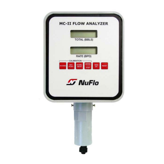
MC-II Flow Analyzer Introduction The NuFlo MC-II Flow Analyzer combines with a turbine flowmeter to provide an accurate display of accu- mulated flow volume and flow rate of liquids and gases in a simple-to-use, battery-powered instrument. The MC-II’s microprocessor circuitry counts the pulses generated by a companion flowmeter, converts that data into volume and rate values in accordance with calibration settings, and displays the totalized data on two six-digit liquid crystal displays (LCD’s). - Page 6 MC-II Flow Analyzer Figure 1—Nomenclature (exterior)
- Page 7 MC-II Flow Analyzer Figure 2—Nomenclature (interior)
-
Page 8: Specifications - Standard Unit Without Options
MC-II Flow Analyzer Specifications – Standard Unit Without Options Size: 7.3 in. wide x 8.3 in. high x 3.4 in. deep Shipping weight: 6 lb including shipping container Power supply: One lithium battery (supplied with instrument), Part No. 100005111 Average battery life: 3 to 5 years Temperature range: °... -
Page 9: Installation
MC-II Flow Analyzer Installation General The MC-II Flow Analyzer is most commonly mounted directly on top of its companion flowmeter. However, if the flowmeter is in a line that has vibration or if the meter’s location makes a direct mount difficult, the MC- II can be mounted on vertical or horizontal 2-in. - Page 10 MC-II Flow Analyzer Figure 3—Direct mount dimensions (inches and millimeters) Figure 4—Remote mount dimensions (inches and millimeters)
-
Page 11: Attaching Switchplate Labels
MC-II Flow Analyzer To install the MC-II with the remote mount option, perform the following steps: 1. Place the “U” bolts around the pipe the MC-II is to be mounted on, then through the mounting bracket. Note that the holes in the mounting bracket are arranged such that it may be used with horizontal or verti- cal pipe. -
Page 12: Wiring The Mc-Ii Circuit Board
MC-II Flow Analyzer Wiring the MC-II Circuit Board The MC-II’s simplistic design makes wiring easy. See the wiring diagram below for reference in properly wir- ing the MC-II to the battery and the flowmeter. Vmax = 6.0 VDC or peak Voc = 5.88 VDC Isc = 2.94 F mA... -
Page 13: Operating Your Mc-Ii
MC-II Flow Analyzer Operating Your MC-II Volume Units If you purchased a companion NuFlo flowmeter with your MC-II Flow = barrels* Analyzer, the MC-II has been calibrated for use with that flowmeter at the RATE factory, and your MC-II is ready for operation as soon as the installation is completed. -
Page 14: View Calibration Factor
MC-II Flow Analyzer Table 1—MC-II Keypad Functions RUN MODE FUNCTIONS ENTER/STEP Saves current volume total in nonvolatile memory. RESET Allows user to zero the volume. VIEW DIV Displays the current calibration factor. DEC. POINT Changes the position of the decimal point in the TOTAL (top) display. INCREMENT Adjusts the LCD contrast. -
Page 15: Adjust Lcd Contrast
MC-II Flow Analyzer Adjust LCD Contrast Dramatic changes in temperature may cause changes in the LCD contrast. To adjust this contrast in Run mode, press INCREMENT repeatedly or press it and hold to scroll through the various contrast levels. Zero the Total At times, a user may wish to reset the volume total to zero. -
Page 16: Data Entry Tips
2. Record this number (it will remain on the display panel only for a few seconds). 3. Call a Cameron (Measurement Systems Division) representative, and give him/her the number and the serial number of the MC-II. After Press ACCESS + RESET... -
Page 17: Recalibrating Your Mc-Ii
MC-II Flow Analyzer Recalibrating Your MC-II Press ACCESS to enter Calibration mode. If your MC-II was purchased as a system, it was calibrated at the factory with its companion NuFlo turbine flowmeter. Verify the calibration set- tings to ensure that no further calibration is required prior to use. TOTAL If you purchased a stand-alone MC-II without a flowmeter, the MC-II must be calibrated before being operated. - Page 18 MC-II Flow Analyzer Enter the Calibration factor from your turbine flowmeter. (Applicable only when preprogrammed unit is selected for volume.) 3. Locate the calibration factor (pulses per gallon) of the turbine flow- meter. This factor is typically recorded on a plastic tag attached to the meter.
- Page 19 MC-II Flow Analyzer 5. Select or deselect the Pulse Output option. The default setting is OFF. Select or deselect the Pulse Output option. If your MC-II is not configured with the pulse output option, press ENTER/STEP to accept the default setting, OFF, and proceed to Step 6.
- Page 20 MC-II Flow Analyzer Enable or disable the 7. The prompt SEt.tot will appear in the top display, and no (default Preset Total option. setting) will appear in the lower display. a. If you do not need to preset a total, press ENTER/STEP to by- pass this menu selection.
-
Page 21: Example: Liquid Measurement With Preprogrammed Units Of Measure
MC-II Flow Analyzer Example: Liquid Measurement with Preprogrammed Press ACCESS to enter Calibration mode. Units of Measure Calibration Information • The MC-II will be mounted on a 1-in. NuFlo liquid turbine meter. • The meter factor is 907.68 pulses per gallon. •... - Page 22 MC-II Flow Analyzer Set unit of measure for e. Press INCREMENT until 9 is displayed. Press ENTER/STEP RATE. to accept the selection and proceed to the thousands position. Since the meter factor is now entered, the remaining digit to the Factory default setting is bpd.
- Page 23 MC-II Flow Analyzer 6. The upper display will show the prompt CodE and the lower display Deselect the Password will show no. Press ENTER/STEP to accept the factory default no Security option. setting, disabling the security code feature. If YES appears in the lower display, press INCREMENT until no is shown.
-
Page 24: Example: Liquid Measurement With User-Defined Units Of Measure
MC-II Flow Analyzer Example: Liquid Measurement with User-Defined Units of Press ACCESS to enter Calibration mode. Measure Calculating the divisor for liquids is necessary when registering the vol- ume in units other than barrels, gallons, cubic meters, or liters. User-de- fined (USEr) units may be used for the volume total and preprogrammed units for the flow rate. - Page 25 MC-II Flow Analyzer 3. After the diagnostics routine is complete, the upper display will show Enter the calculated divi- the prompt tot.Eng. Press INCREMENT until USEr appears on the sor. lower display. Press ENTER/STEP to confirm the selection. 4. The upper display will show Ent.diV, prompting you for the divisor. The lower display will show the previously entered meter factor (fac- Factory tory default is 230.00).
- Page 26 MC-II Flow Analyzer Set unit of measure for 5. The upper display will show rAt.Eng, prompting you to enter the unit RATE. of measure for the flow rate. Press INCREMENT repeatedly until “per day” (PEr.dAY) appears in the lower display. Since the desired rate is Factory default setting is bpd.
- Page 27 MC-II Flow Analyzer 8. The prompt SEt.tot will appear in the top display, and no (default set- Bypass the Preset Total ting) will appear in the lower display. option. Since no preprogrammed unit is to be entered for this example, press ENTER/STEP to bypass this menu selection.
-
Page 28: Example: Gas Measurement Using A Calculated Divisor
MC-II Flow Analyzer Example: Gas Measurement Using a Calculated Divisor Calculating the divisor for gases is necessary when registering in units other than actual cubic feet (ACF). The USEr volume and flow rate functions of the MC-II are used in this case. Note—Each MC-II is shipped with a label set (Part No.100080190) containing commonly used flow rate and volume units of measure labels. -
Page 29: Maintenance
MC-II Flow Analyzer e. Substitute calculated values for variables in the formula to obtain the divisor. FC × Ps × Tf × CON 72.56 × 14.73 × 509.67 × 35.31 270.2462 Divisor (Pg + Pa) × Ts × (Fpv) (120 + 14.21) × 519.67 × (1.0102) Round the divisor to six digits (to accommodate the six-digit limit of the MC-II display). - Page 30 MC-II Flow Analyzer Circuit Assembly Replacement The circuit assembly (Part No. 100005109) contains all of the electronic components. To retain the current volume information for reentering into a new replacement unit, record the totalized volume and rate informa- tion before uninstalling the circuit assembly. CAUTION: Before opening the enclosure, make sure the enclosure is in a well-ventilated area and avoid breathing fumes that could be trapped inside.
- Page 31 CAUTION: Use of spare parts other than those identified by Cameron’s Measurement Systems Division voids CSA certification. Cameron bears no legal responsibility for the performance of a product that has been serviced or repaired with parts that are not authorized by Cameron. BASIC MC-II SPARE PARTS LIST...
- Page 32 MC-II Flow Analyzer...
-
Page 33: Appendix A-Pulse Output Option, Non-Intrinsically Safe
MC-II Flow Analyzer Appendix A—Pulse Output Option, Non-Intrinsically Safe MC-II Pulse Output Circuit Assembly (Part No. 100005121; nonhazardous use) The pulse output circuit assembly (Figure A1) equips the MC-II Flow Analyzer to provide an optional pulse output. It is mounted inside the unit between the totalizer board and the battery. WARNING: Do not use in hazardous areas. -
Page 34: Data Entry Tip
MC-II Flow Analyzer Installing the Pulse Output Circuit Assembly A 6-pin terminal strip and two mounting holes in the pulse output circuit assembly allow for easy installation. To install the pulse output option, perform the following steps: 1. Confirm that the W1 jumper is set in the “Divide by 1” position. This setting allows you to configure the pulse output scale using the keypad on the front of the enclosure. - Page 35 Figure A2—Field wiring for dry contact pulse output option (non-hazardous areas)
- Page 36 Figure A3—Field wiring for open collector pulse output option (non-hazardous areas)
- Page 37 Figure A4—Field wiring for opto-isolated pulse output option (non-hazardous areas)
- Page 38 MC-II Flow Analyzer...
-
Page 39: Appendix B-Pulse Output Option, Intrinsically Safe
MC-II Flow Analyzer Appendix B—Pulse Output Option, Intrinsically Safe MC-II Pulse Output Circuit Assembly (Part No. 100005163; Intrinsically Safe) The pulse output circuit assembly (Figure B1) equips the MC-II Flow Analyzer to provide an optional pulse output. It is mounted inside the unit between the totalizer board and the battery cavity. Important—When this circuit assembly is installed according to Figures B2, B3 and B4 (pages 35 and 36), the MC-II with pulse output is rated by Canadian Standards Association as Intrinsically Safe for Class I, Division 1, Groups A,B,C and D. -
Page 40: Data Entry Tip
MC-II Flow Analyzer Installing the Pulse Output Circuit Assembly A 6-pin terminal strip and two mounting holes in the pulse output circuit assembly allow for easy installation. To install the pulse output option, perform the following steps: 1. Confirm that the W1 jumper is set in the “1” position. This setting allows you to configure the pulse out- put scale using the keypad on the front of the enclosure. - Page 41 Figure B2—Field wiring for dry contact pulse output option (MC-II Flow Analyzer is CSA-approved for use in HAZARDOUS areas when installed in accordance with drawing 101231210 shown above) Figure B3—Field wiring for open collector pulse output option (MC-II Flow Analyzer is CSA-approved for use in HAZARDOUS areas when installed in accordance with drawing 101231210 shown above)
- Page 42 Figure B4—Field wiring for opto-isolated pulse output option (MC-II Flow Analyzer is CSA-approved for use in HAZARDOUS areas when installed in accordance with drawing 101231210 shown above)
- Page 43 Federal law requires that depleted lithium batteries be sent to a fully permitted Treatment, Storage and Dis- posal Facility (TSDF) or to a permitted recycling/reclamation facility. Important: Do not ship lithium batteries to Cameron’s Measurement Systems Division. Cameron facili- ties are not permitted recycling/reclamation facilities.
- Page 44 MC-II Flow Analyzer...
- Page 47 WARRANTY - LIMITATION OF LIABILITY: Seller warrants only title to the products, soft- ware, supplies and materials and that, except as to software, the same are free from defects in workmanship and materials for a period of one (1) year from the date of delivery. Seller does not warranty that software is free from error or that software will run in an uninterrupted fashion.
Need help?
Do you have a question about the NuFlo MC-II and is the answer not in the manual?
Questions and answers