
Related Manuals for Cameron NUFLO EZ-IN Series


Summary of Contents for Cameron NUFLO EZ-IN Series
- Page 1 Class I, Group A, B, C, D, Division I Complies with ASME Standard B31.3 NUFLO™ EZ-IN Series ® Turbine Flowmeter Installation Manual Part No. 9A-100062997, Rev. 01 Measurement Systems...
- Page 2 EZ-IN Series BF Turbine Flowmeter Manual ® Part No. 9A-100062997, Rev. 01 September 2008 © 2008 Cameron International Corporation (“Cameron”) Printed in USA All Rights Reserved...
-
Page 3: Table Of Contents
Table of Contents Introduction ....................5 Installation ....................10 Precautions ..................10 Installation Procedure ............... 11 Calibration ....................12 Maintenance and Repairs................ 14 Removing the Meter from the Pipeline ..........14 Disassembling the Hex-Body Meter ..........15 Reassembling the Hex-Body Meter ..........16 Disassembling the Round-Body Meter .......... - Page 4 EZ-IN Series Turbine Flowmeter Manual ® Internal Components Repair Kit for Round-Body Meters ....27 Retainer Rings for Hex-Body Meters ..........28 Hardware Kits and Centering Rings (Raised Face Flanges) .... 29 Hardware Kits (Ring Joint Flanges) ..........30 Magnetic Pickups and Replacement Lock Nuts ........ 30...
-
Page 5: Introduction
Introduction The EZ-IN Series Between-Flange Turbine Flowmeter measures ® flowstream volume in flanged pipelines by transmitting electrical pulses to readout instruments. The flowmeter’s precision turbine has a rotational velocity proportional to the linear velocity of the fluid flowing through the meter. As the turbine rotates, the blades break magnetic lines of force set up by a magnetic pickup screwed into the meter body. - Page 6 EZ-IN Series Turbine Flowmeter Manual ® Conduit adapter Downstream vane Retainer ring Rotor (2 typ.) Upstream vane Figure 1—Internal components for hex-body flowmeters (1-in. end connection)
- Page 7 Figure 2—Internal components for round-body flowmeters (2-in. or larger end connection)
- Page 8 EZ-IN Series Turbine Flowmeter Manual ® An installation handle (Figure 3) is available to allow easier installation and removal (Part No. 9A-100079570). An optional 3/4-in. thin-wall pickup lock-nut socket is also available (Part No. 9A-100013146). Body centering All-thread studs rings and nuts Figure 3—Assembled flowmeter with optional installation handle...
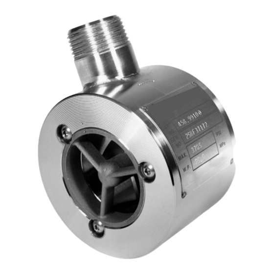
- Page 9 Flowmeter identification data and specifications are engraved on the flowmeter body or printed on a stainless steel tag, which is attached to the meter body (Figure 4). Figure 4—Product identification tag on flowmeter body...
-
Page 10: Installation
EZ-IN Series Turbine Flowmeter Manual ® Installation Precautions The EZ-IN Series Between-Flange Turbine Flowmeter can be installed ® vertically or horizontally. In either orientation, the arrow on the meter body must point in the direction of flow in the line. •... -
Page 11: Installation Procedure
• If the end connection leaks at the time of installation, remove pressure- before attempting to tighten the seal. • The customer is responsible for ensuring chemical compatibility between the flowmeter and any fluids being metered. • The meter will attain the temperature of the fluid. Use caution when touching the meter body to avoid burns. -
Page 12: Calibration
EZ-IN Series Turbine Flowmeter Manual ® the holes in the bottom half of the flanges (Figure 5, page 13). Install additional nuts inside the flanges, if needed, to separate the flanges while inserting the meter. (See “spreader” nuts in Figure 3, page 8.) Lower the meter between the flanges and align the bore with the flow- line. - Page 13 Pickup adapter extension All-thread stud Spreader nut Figure 5—Meter installation diagram...
-
Page 14: Maintenance And Repairs
EZ-IN Series Turbine Flowmeter Manual ® Maintenance and Repairs If flowmeter readings appear erratic, check the flowmeter for wear or debris. Under normal operation with non-abrasive fluids, flowmeters can provide years of service without repairs. If a flowmeter is exposed to abrasive fluids or long periods of over-range flow rates, an annual check is recommended. -
Page 15: Disassembling The Hex-Body Meter
Disassembling the Hex-Body Meter Assembly and disassembly procedures vary with the type of flowmeter installed. For instructions on repairing a round-body meter, see page 19. To disassemble a hex-body meter, follow the steps below. Remove the retaining ring from one end of the meter body. Remove the vane from the meter body. -
Page 16: Reassembling The Hex-Body Meter
EZ-IN Series Turbine Flowmeter Manual ® Reassembling the Hex-Body Meter • An arrow indicating direction of flow is cast or engraved on the meter body, rotor, and vanes. When the meter is assembled, all arrows must point in the direction that product will flow through the meter. •... - Page 17 To reassemble a hex-body meter, follow the steps below: Insert a vane into the meter body, ensuring that the flow arrow is point- ing in the direction of flow and the marked blade is positioned at the bottom of the bore (Figure 6, page 18). The vane should fit snugly but should not require excessive force to install.
- Page 18 EZ-IN Series Turbine Flowmeter Manual ® 1. Insert the vanes so that the arrow on the blade points in the direction of flow. 2. Make sure that the blade with the arrow marking is positioned in the notch closest to the bottom of the meter bore. Figure 6—Positioning of vanes...
-
Page 19: Disassembling The Round-Body Meter
Disassembling the Round-Body Meter Assembly and disassembly procedures vary with the type of flowmeter installed. For instructions on repairing a hex-body meter, see page 15. To disassemble a round-body meter, follow the steps below: Remove the three socket-head capscrews from one end of the meter using a standard Allen wrench. -
Page 20: Reassembling The Round-Body Meter
EZ-IN Series Turbine Flowmeter Manual ® Remove the three socket-head capscrews from the other end of the me- ter body. Remove the second bearing support, rotating it if necessary. Examine the carbide bearing and rotor shaft. If either part is worn or damaged, replace all internals with a repair kit (page 28). - Page 21 To reassemble a round-body meter, follow the steps below: Insert a bearing support in the meter body, ensuring that the flow arrow is pointing in the direction of flow and the punch marks on the support and meter body are aligned (Figure 7, page 22). Install the three socket-head capscrews to secure the bearing support, and tighten them with a standard Allen wrench.
- Page 22 EZ-IN Series Turbine Flowmeter Manual ® Insert each bearing support such that the punch mark aligns with the punch mark on the face of the flowmeter. Figure 7—Positioning of bearing supports...
-
Page 23: Returning The Meter To The Pipeline
Returning the Meter to the Pipeline Return the meter to the line, using the body centering rings (Figure 3, page 8) to align the meter with the inside diameter of the flanges. Care- fully align the flange gaskets with the flanges to help prevent gasket damage. -
Page 24: Specifications And Parts Lists
EZ-IN Series Turbine Flowmeter Manual ® Specifications and Parts Lists Temperature and Pressure Ratings Flange Classification CL 150 CL 300 CL 600 CL 900 CL 1500 CL 2500 Design-Operating Maximum Working Pressure Temperature Range psi (mPa) -20 to l00°F 1480 2220 3705 6170... -
Page 25: Flow Ranges
Flow Ranges Linear Flow Ranges (based on water) Nominal Meter Bore Calibration Max. Output ∆p at Max. Flow Size Factor Frequency psi (kPa) gal/min pulses/gal pulses/sec (pulses × 1000/m 0.46 to 3 0.104 to 0.68 10 to 100 22,000 (5812) 1,100 4 (28) 0.80 to 7.5... -
Page 26: Internal Components Repair Kit For Hex-Body Meters
EZ-IN Series Turbine Flowmeter Manual ® Internal Components Repair Kit for Hex-Body Meters Meter Bore Size End Connection Size Standard Grade Industrial Grade Linearity ± 1.0% Linearity ± 0.5 % 9A-100003521 9A-100003378 9A-100003531 9A-100003379 9A-100003449 9A-100003380 9A-100005124 9A-100061059 9A-100003527 9A-100003381 Linearity for a 3/8-in. -
Page 27: Internal Components Repair Kit For Round-Body Meters
Internal Components Repair Kit for Round-Body Meters Meter Bore Size End Connection Size Standard Grade Industrial Grade Linearity ± 1.0% Linearity ± 0.5 % 9A-100079691 — 9A-100005122 9A-100062982 9A-100079674 9A-100062983 9A-100079811 9A-101209539 9A-100005123 9A-100062984 1 1/2 9A-100005099 9A-100062985 9A-100003553 9A-100003549 9A-100003540 9A-100012104 9A-100003554... -
Page 28: Retainer Rings For Hex-Body Meters
EZ-IN Series Turbine Flowmeter Manual ® Retainer Rings for Hex-Body Meters (Purchased Separately from Repair Kit) Meter Bore Size End Connection Size Retainer Ring Part Number 9A-100003414 9A-100003415... -
Page 29: Hardware Kits And Centering Rings (Raised Face Flanges)
Hardware Kits and Centering Rings (Raised Face Flanges) Hardware Kits Size (in.) CL 150 CL 300 CL 600 CL 900 CL 1500 9A-100014135 9A-100009578 9A-100009578 9A-100079754 9A-100079754 1 1/2 and 2 9A-100003555 9A-100003556 9A-100003556 9A-100003557 9A-100003557 9A-100003558 9A-100007860 9A-100007860 9A-100003559 9A-100012105 9A-100003560 9A-100003561 9A-100003562 9A-100063005 9A-100063006 9A-100063007 9A-100063008 9A-100012106 9A-100063009 9A-100063010 9A-100063011 9A-100063012 9A-100063013 9A-101209537 9A-101209536... -
Page 30: Hardware Kits (Ring Joint Flanges)
EZ-IN Series Turbine Flowmeter Manual ® Hardware Kits (Ring Joint Flanges) Size (in.) CL 900 CL 1500 CL 2500 1 1/2 and 2 9A- 100014145 9A- 100014145 9A- 100080024 9A-101213513 9A- 100079971 9A- 101203294 9A- 100079986 9A- 100079960 9A- 101209541 9A- 100080034 9A- 100080023 9A-101215223... - Page 31 Warranty—Limitation of Liability WARRANTY - LIMITATION OF LIABILITY: Seller warrants only title to the products, software, supplies and materials and that, except as to software, the same are free from defects in workmanship and materials for a period of one (1) year from the date of delivery. Seller does not warranty that software is free from error or that software will run in an uninterrupted fashion.
- Page 32 Cameron_NuFlo测量系统_流量及控制类仪表联系方式: 信德迈科技(北京)有限公司 CNMEC Technology Company 地址:北京朝阳区望京街10号望京SOHO-T1-C座2115室 邮编:100102 电话:010-8428 2935, 8428 9077, 8428 3983 手机:139 1096 2635 Http://www.cnmec.biz E-mail:sales@cnmec.biz 传真:010-8428 8762...
Need help?
Do you have a question about the NUFLO EZ-IN Series and is the answer not in the manual?
Questions and answers