
Related Manuals for Cameron NUFLO MC-III EXP


Summary of Contents for Cameron NUFLO MC-III EXP
- Page 1 Valves & Measurement NUFLO MC-III™ EXP Flow Analyzer User Manual Manual No. 9A-50165003, Rev. 06...
-
Page 2: Important Safety Information
Important Safety Information Symbols and Terms Used in this Manual WARNING: This symbol identifies information about practices or circumstances that can lead to per- sonal injury or death, property damage, or economic loss. CAUTION: Indicates actions or procedures which if not performed correctly may lead to personal injury or incorrect function of the instrument or connected equipment. -
Page 3: Table Of Contents
MC-III™ EXP Flow Analyzer Table of Contents Contents Important Safety Information ..........................ii Section 1—Introduction ........................... 1 Operation ................................1 Product Identification ............................2 Key Product Features ............................5 LCD Display ..............................5 Keypad ................................. 6 Interface Software ............................6 Power Supply—CSA-Approved Units ......................7 Power Supply—ATEX-Approved Units ...................... - Page 4 Table of Contents MC-III™ EXP Flow Analyzer Section 3—Configuration and Operation via Keypad ................. 29 Entering a Calibration Factor ........................... 30 Entering a Calculated Divisor ........................... 31 Setting Input Type and Sensitivity ........................32 Configuring the Total Display ..........................33 Configuring the Rate Display ..........................
- Page 5 MC-III™ EXP Flow Analyzer Table of Contents Pulse Output ..............................67 Configuring Pulse Output ........................... 67 Pulse Output Testing ..........................68 Saving and Uploading Configuration Files ....................... 69 Saving a Configuration File ........................69 Uploading a Configuration File ........................70 Advanced Access ............................
- Page 6 Table of Contents MC-III™ EXP Flow Analyzer Toggle RTS Line Option ..........................B-4 Enable Modbus Address Support for Firmware Versions 1.06 through 1.08 ..........B-4 Timing Parameters ............................B-4 Downloading Options ............................B-5 Advanced Options ............................B-6 Clear EEPROM ............................B-6 Automatic Data Logging ..........................B-6 Appendix C—Lithium Battery Information ....................C-1 Lithium Battery Disposal ..........................C-1 Transportation Information ..........................C-1 Material Safety Data Sheet..........................C-1...
-
Page 7: Section 1-Introduction
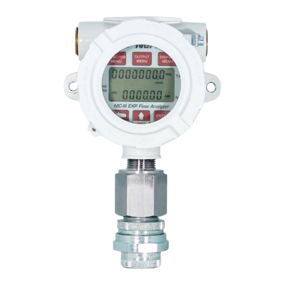
MC-III™ EXP Flow Analyzer Section 1 Section 1—Introduction The NuFlo™ MC-III™ EXP Flow Analyzer (Figure 1.1) packs a full spectrum of gas and liquid measurement functionality, high-speed performance, and log archive and retrieval capabilities in an easy-to-use, explosion- proof totalizer. Commonly used operations can be accessed from the six-button keypad on the front of the instrument or from the dynamic interface software, allowing you to calibrate and configure the unit quickly and easily. -
Page 8: Product Identification
Section 1 MC-III™ EXP Flow Analyzer With the press of a single key, totals are saved to nonvolatile memory, minimizing the risk of data loss even if a power outage occurs. Up to 384 daily logs, 768 hourly logs, and 345 event logs can be archived and accessed quickly on demand. Offering a variety of user-configurable display options, input and output options, RS-485 Modbus ®... - Page 9 MC-III™ EXP Flow Analyzer Section 1 Table 1.1—MC-III EXP Specifications Approved by CSA for US and Canada Electrical Safety Classification Class I, Div. 1, Groups B, C, D (explosion-proof) Type 4 enclosure T6 temperature class Approved by SIRA to ATEX 10ATEX 1264X IECEx SIR10.0127X II 2 GD Ex db IIC T6 Gb (-40°C to 70°C) or Ex tb IIIC T85°C Db (-40°C to 70°C)
- Page 10 Section 1 MC-III™ EXP Flow Analyzer Table 1.1—MC-III EXP Specifications Turbine Meter Input Inputs Configurable sensitivity adjustment via front panel Sensitivity adjustment range: 20 mV P-P to 40 mV P-P Frequency range: 0 to 3500 Hz Remote Reset Input Optically isolated 3.0 to 30 VDC Pulse duration >...
-
Page 11: Key Product Features
MC-III™ EXP Flow Analyzer Section 1 Table 1.1—MC-III EXP Specifications Operating System - Windows XP, Windows Vista , or Windows 7 ® System Requirements Computer/Processor - 1 GHz or faster Pentium-compatible CPU Memory - 128 MB of RAM Hard Disk Space - 21 MB for program files, 30 MB for Adobe Reader, adequate space for data files Drive - CD-ROM for install Display - 800 x 600 (SVGA), 16-bit (thousands of colors) color display or... -
Page 12: Keypad
Section 1 MC-III™ EXP Flow Analyzer gallons per minute). Also, the volume unit used for the flow rate can be different from the volume unit used to read Total volume. The unit of measure for the Rate readout and the decimal point position are selected by the operator during calibration. -
Page 13: Power Supply-Csa-Approved Units
MC-III™ EXP Flow Analyzer Section 1 Enable/disable/set up 4-20 mA output Enable/disable/set up pulse output Enter slave address Enter baud rate Set engineering units for Total readout Set engineering units for Rate readout Calibrate instrument Set decimal placement for both readouts Set flowmeter input sensitivity Select pulse input K-FACTOR... -
Page 14: Multipoint Linearization
Section 1 MC-III™ EXP Flow Analyzer Multipoint Linearization The MC-III interface software supports up to 12 calibration points in addition to single-point calibration based on the K-factor provided with the turbine flowmeter. See 62, for more information. K-Factor Type, page Gas Volume Correction Gas turbine meters are calibrated in actual cubic feet (ACF), and measure gas in actual cubic feet. -
Page 15: Optional Features
MC-III™ EXP Flow Analyzer Section 1 Password-protected security access is enabled using the interface software. When this feature is enabled, the user will be prompted for a password when attempting to enter any menu from the keypad. For more information, see Security Setup, page Optional Features Explosion-Proof Reset/Control Switch... -
Page 16: Is Barrier (Csa-Approved Units Only)
Section 1 MC-III™ EXP Flow Analyzer Important: The USB communications adapter is approved by CSA for use in hazardous areas. The CSA-approved model is Part No. 2295524-01. The adapter kit, which includes an installa- tion CD, is Part No. 2295634-01. RS-485 IS Barrier (CSA-Approved Units Only) The RS-485 output of a CSA-approved MC-III is approved for intrinsically safe installations. -
Page 17: Viewing Daily And Hourly Logs
MC-III™ EXP Flow Analyzer Section 1 • To reset the total with an explosion-proof switch, press and hold the switch for 3 seconds, then release it. See also Explosion-Proof Reset/Control Switch, page • To reset the total with an external pulse generator located in safe area, configure the pulse to be active for 3 seconds. - Page 18 Section 1 MC-III™ EXP Flow Analyzer...
-
Page 19: Section 2-Installation
Hazardous Area Installations (CSA), page Cameron recommends that operators configure the device prior to mounting if the instrument is to be installed in a hazardous area. The enclosure must be opened to configure the device, either via keypad controls or via software. -
Page 20: Conditions For Safe Use (Atex)
Installation shall be carried out by suitably trained personnel in accordance with the applicable code of practice (EN 60079-14 within Europe). • Repair of this equipment shall be carried out by Cameron or in accordance with the instructions in this manual. •... -
Page 21: Mounting Options (Atex)
MC-III™ EXP Flow Analyzer Section 2 Mounting Options (ATEX) The ATEX-approved MC-III EXP may be mounted directly to a flowmeter, or mounted remotely on a pole and connected to a flowmeter with explosionproof signal cable. The type of meter mount required varies with the meter in use. - Page 22 Section 2 MC-III™ EXP Flow Analyzer 5.71 (145) 5.71 (145) 9.29 4.94 (236.1) (125.5) approx. Figure 2.3—Direct mount to a Barton 7000 series flowmeter with 3/4-in. to 3/4-in. standoff tube (ATEX) 5.00 (127) 4.94 (125.5) 7.45 (189.3) 6.56 (16.7) 6.95 (17.65) Figure 2.4—Remote mount on a 2-in.
-
Page 23: Hazardous Area Installations (Csa)
CSA-approved battery supplied by Cameron (Part No. 9A-100005111). • Replace the optional alkaline battery pack only with the CSA-approved battery pack supplied by Cameron (Part No. 9A-50099002). • The lithium battery that powers the MC-III EXP is a sealed unit; however, should a lithium battery develop a leak, toxic fumes could escape upon opening the enclosure. - Page 24 Section 2 MC-III™ EXP Flow Analyzer • Mount the device to a flat, vertical surface. The standard enclosure is ideal for a bulkhead mount; the alternate enclosure is not recommended for bulkhead mounting. • Remote-mount the device to a 2-in. pole using a NuFlo hardware kit (Figure 2.7, page 19).
-
Page 25: Installing The Mc-Iii Exp
MC-III™ EXP Flow Analyzer Section 2 union (CSA) 5.00 (127) 4.94 (125.5) 7.45 (189.3) 6.56 (16.7) 6.95 (17.65) Figure 2.7—Remote mount on a 2-in. pole using a NuFlo hardware kit (Part No. 9A-30028004) Installing the MC-III EXP If the device is to be installed in a hazardous area, configure the device prior to mounting it. See Sections 3 and 4 for instructions. -
Page 26: Field Wiring
Section 2 MC-III™ EXP Flow Analyzer Field Wiring The MC-III EXP supports connections for the following: internal power (battery), external power, turbine flowmeter input, pulse input, remote reset input, pulse output, 4 to 20 mA output, flowmeter frequency (amp & square) output, and RS-485 output. Wiring diagrams for each connection are provided below. -
Page 27: Internal Power Supply
MC-III™ EXP Flow Analyzer Section 2 Internal Power Supply The MC-III EXP is shipped with one of three internal power supplies: • a CSA-approved 3.6V lithium battery • an ATEX-approved 3.6V lithium battery • a shrink-wrapped alkaline battery pack containing three C-size industrial-grade batteries (available only with CSA-approved devices) Low-power microprocessor technology enables the MC-III EXP analyzer to operate approximately 2 years on a single lithium battery. -
Page 28: Turbine Flowmeter (Tfm) Input
Section 2 MC-III™ EXP Flow Analyzer Turbine Flowmeter (TFM) Input The TFM input provides the turbine flowmeter input signal generated by a magnetic pickup, enabling the MC- III EXP to calculate and display instantaneous flow rates and accumulated totals. EXT POWER A&S TURBINE MAGNETIC PICKUP... -
Page 29: Remote Reset Input
MC-III™ EXP Flow Analyzer Section 2 Remote Reset Input The remote reset input allows the operator to reset the accumulated volume on the MC-III EXP to zero without opening the enclosure. This input is optically isolated. The input is shown connected in two ways, with a power supply and switch in a safe area (Figure 2.11), and with a pulse generator in a safe area (Figure 2.12). -
Page 30: Pulse Output
Section 2 MC-III™ EXP Flow Analyzer Pulse Output The pulse output is a solid-state relay. Each pulse represents a user-defined volume. Because the circuit is isolated, it can be used in conjunction with any other feature on the MC-III EXP. A two-conductor cable from the MC-III EXP to the remote location is required (Figure 2.13). -
Page 31: Analog (4-20 Ma) Rate Output
MC-III™ EXP Flow Analyzer Section 2 Analog (4-20 mA) Rate Output The 4-20 mA rate output provides a linear current output that represents flow rate. This output requires a two- conductor cable connected to an 8 to 30 VDC power supply (voltage required is dependent on loop resistance) and a current readout device located in the remote location. -
Page 32: Flowmeter Frequency Output
Section 2 MC-III™ EXP Flow Analyzer Flowmeter Frequency Output The flowmeter frequency (amp & square) output provides an open drain transistor output at the turbine meter frequency, which may be used to provide flow rate and/or total information to peripheral equipment. The output requires a two-conductor cable from the MC-III EXP to the remote frequency readout device requiring 50 mA or less and a 5 to 30 VDC power supply (Figure 2.15). -
Page 33: Rs-485 Output
MC-III™ EXP Flow Analyzer Section 2 RS-485 Output The RS-485 output is required for communication with the interface software. Wiring diagrams are provided for a permanent connection (Figure 2.16), as well as for temporary laptop connections using an RS-485 to RS- 232 converter (Figure 2.17). - Page 34 Section 2 MC-III™ EXP Flow Analyzer Figure 2.18—Intrinsically safe RS-485 connection, based on control drawing 9A-50053010 (applicable to CSA-approved device only)
- Page 35 MC-III™ EXP Flow Analyzer Section 2...
-
Page 36: Section 3-Configuration And Operation Via Keypad
Section 3 MC-III™ EXP Flow Analyzer Section 3—Configuration and Operation via Keypad Calibration of the MC-III™ EXP is a simple matter of entering necessary parameters into the instrument. The process for calibrating the MC-III EXP depends on how the instrument will be used. The keypad can be used to calibrate the MC-III EXP for liquid or gas measurement using preprogrammed units, or for liquid measurement using a calculated divisor. -
Page 37: Entering A Calibration Factor
MC-III™ EXP Flow Analyzer Section 3 Entering a Calibration Factor When the volume is to be expressed in barrels (BBL), gallons (GAL), liters (LIT), cubic meters (M ), or cubic feet (CF), and the flow rate is to be expressed in barrels, gallons, liters, cubic meters or cubic feet per day, per hour, per minute, or per second, the MC-III EXP calculates the divisor automatically;... -
Page 38: Entering A Calculated Divisor
Section 3 MC-III™ EXP Flow Analyzer Entering a Calculated Divisor When registering the volume in units other than cubic meters, cubic feet, barrels, gallons, or liters, a calculated divisor must be entered in the K-Factor menu instead of the turbine meter calibration factor. Important: When a calculated divisor is used, the units for both the volume display and the volume portion of the flow rate display should be set to USER (no units visible on the display). -
Page 39: Setting Input Type And Sensitivity
MC-III™ EXP Flow Analyzer Section 3 Setting Input Type and Sensitivity The flowmeter signal can be obtained from a magnetic pickup or a pre-amplifier device. The input sensitivity of the MC-III EXP is measured in millivolts (mV) peak-to-peak. This is the threshold value at which the circuitry responds to a signal. -
Page 40: Configuring The Total Display
Section 3 MC-III™ EXP Flow Analyzer Configuring the Total Display The Total display can be configured for measuring volume in any of five preprogrammed units, any preprogrammed unit times 1,000, or a user-defined unit. Users can specify a decimal point position ranging from 0.1 to 0.0001 of a unit. The device will display volumes up to 10,000,000, however, a maximum of eight digits (including decimals) are visible at a time. -
Page 41: Configuring The Rate Display
MC-III™ EXP Flow Analyzer Section 3 Configuring the Rate Display The Rate display comprises two parts: a volume unit and a time-base unit. The volume portion of the Rate display can be configured in one of five preprogrammed engineering units or in a user-defined unit (for use with a calculated divisor). -
Page 42: Configuring The 4-20 Ma Rate Output
Section 3 MC-III™ EXP Flow Analyzer Configuring the 4-20 mA Rate Output Caution: Before performing any 4-20 mA configuration, ensure that all peripheral equipment con- nected to the 4-20 mA current loop is either disconnected or disabled. Configuring and testing the 4-20 mA output feature on the MC-III EXP with the peripheral equipment in operation may cause false alarms or erroneous operation of the peripheral device or as- sociated equipment. - Page 43 MC-III™ EXP Flow Analyzer Section 3 To Configure the 4-20 mA Output: Enter the Output menu. Press OUTPUT MENU. OUTPUT MENU Enable or disable the 4-20 mA output. Press UP ARROW to toggle output to Toggles between “on” or “off”. “off”...
-
Page 44: Configuring The Pulse Output
The pulse output feature of the MC-III EXP is typically disabled to reduce current consumption. When the pulse output is not needed, Cameron recommends that this feature be disabled. If the pulse output feature is required, the user will be prompted to enter a pulse output scale factor, which is the volume increment that will cause a pulse output to occur. -
Page 45: Entering The Slave Address
MC-III™ EXP Flow Analyzer Section 3 Entering the Slave Address The slave address is a setting used in Modbus communications. It is a number that ranges from 1 to 65535, ® excluding 252 to 255 and 64764. If the Modbus request message contains the matching address, the ®... - Page 46 Section 3 MC-III™ EXP Flow Analyzer...
-
Page 47: Section 4-Configuration And Operation Via Software
MC-III™ EXP Flow Analyzer Section 4 Section 4—Configuration and Operation via Software The MC-III™ interface software provides easy access to all configuration parameters and is the quickest way to configure the device. While basic parameters can be configured with the keypad (see Section 3), the interface software is the only means of accessing every configurable parameter. -
Page 48: Connecting The Mc-Iii To A Computer
Section 4 MC-III™ EXP Flow Analyzer Connecting the MC-III to a Computer Before attempting to run the interface software, verify that the Scanner is connected to a computer with an RS-485 to RS-232 converter or an RS-485 to USB converter. •... -
Page 49: Automating Functions On Software Startup
MC-III™ EXP Flow Analyzer Section 4 Figure 4.3—Prompt for authorizing time and date synchronization The time difference setting used to generate a synchronize prompt is user-configurable. For more information, General Options, page B-1. Automating Functions on Software Startup When the software connects with the instrument, the Device Autorun Options screen appears (Figure 4.4). From this screen, users can configure the instrument, download logs, or upload previously saved configuration settings. -
Page 50: Changing Autorun Settings
Section 4 MC-III™ EXP Flow Analyzer Changing Autorun Settings To change an autorun setting —that is, to initiate an autorun action, to terminate an autorun action, or to change to a different autorun action—without exiting to the Welcome screen, choose Options/Program Options from the menu bar and select Autorun from the dropdown list (Figure 4.5). -
Page 51: Changing The Communications Port
MC-III™ EXP Flow Analyzer Section 4 Figure 4.6—Cancel Express Connect option Changing the Communications Port The computer will attempt to connect to the MC-III EXP via the port that the user selects the first time he connects to the instrument. However, if a network dictates that the computer connect through another communications port (actual or virtual), the user must specify the appropriate COM port. - Page 52 Section 4 MC-III™ EXP Flow Analyzer To select a device from a network of instruments, perform the following: 1. From the Welcome screen, choose File>Cancel Express Connect (Figure 4.6, page 45). 2. Click File>Discover Modbus Slaves. ® 3. Enter a range of addresses you want to search (Figure 4.8). 4.
-
Page 53: Setting Log Download Preferences
MC-III™ EXP Flow Analyzer Section 4 Setting Log Download Preferences The MC-III EXP automatically saves daily flow logs on the contract hour, and hourly flow logs around the clock. The instrument also automatically creates an event record each time a user change is made. After downloading these logs from the instrument, the instrument saves the data in a file. -
Page 54: Configuring The Mc-Iii Exp
Section 4 MC-III™ EXP Flow Analyzer Configuring the MC-III EXP The MC-III EXP offers three methods for configuring parameters: • The “Configuration Wizard” (Figure 4.11) condenses the configuration process into nine easy-to-follow steps (compensated gas measurement and multipoint linearization are not supported in the wizard). •... - Page 55 MC-III™ EXP Flow Analyzer Section 4 Figure 4.12—MC-III Main configuration option for complete access to configurable parameters Figure 4.13—Advanced Access configuration option for system configurators and host programmers...
-
Page 56: Configuration Wizard
Section 4 MC-III™ EXP Flow Analyzer Configuration Wizard The Configuration Wizard is ideal for first-time users who want to perform a basic calibration for liquid or gas measurement. By following the instructions on nine screens, even a first-time user can successfully configure the MC-III EXP. - Page 57 MC-III™ EXP Flow Analyzer Section 4 Table 4.1—Menus for Configuring Parameters Configurable Parameter Configuration Instrument Menu Screen Keypad Wizard (accessed from information, MC-III Main) see… Well Name — Step 1 Wellsite page 59 Information LCD Contrast — — System Setup page 56 Security Setup —...
-
Page 58: Mc-Iii Main Screen
Section 4 MC-III™ EXP Flow Analyzer MC-III Main Screen The MC-III Main menu screen (Figure 4.15) is the configuration hub of the MC-III EXP. From the Main screen, users can • review all current instrument settings and flow readings • check the log archive and instrument status •... -
Page 59: Buttons And Tools
MC-III™ EXP Flow Analyzer Section 4 Buttons and Tools Apply and OK Buttons Changing parameters on a submenu screen involves selecting the proper screen from the scroll bar, selecting information from dropdown menus or entering data in data fields, and saving the data using the “Apply” or “OK”... - Page 60 Section 4 MC-III™ EXP Flow Analyzer Configuration Submenus (See Scroll Bar on MC-III Main Screen) System Setup Communications Port Wellsite Information Turbine Input K-Factor Entry 4-20 mA Output...
- Page 61 MC-III™ EXP Flow Analyzer Section 4 Configuration Submenus (cont’d) Pulse Output Flow Archive Event Archive...
-
Page 62: System Setup
Section 4 MC-III™ EXP Flow Analyzer System Setup The first of the submenus on the Main screen scroll bar—System Setup—allows users to adjust time/date, set the desired contract hour, enable or disable the password-protected security option, and adjust the LCD contrast (Figure 4.17). -
Page 63: Security Setup
MC-III™ EXP Flow Analyzer Section 4 Security Setup Setting a keypad security code will prevent unauthorized personnel from altering calibration data or resetting totals, and the security function is recommended to preserve data integrity of the system. The MC-III EXP’s keypad security feature is disabled at the factory. -
Page 64: Baud Rate
Section 4 MC-III™ EXP Flow Analyzer To change the slave address, select a number using the “plus” and “minus” buttons on the screen, or using the page-up and page-down keys on your computer keyboard. If Modbus communication is not used, leave the ®... -
Page 65: Bus Delay
MC-III™ EXP Flow Analyzer Section 4 Bus Delay Bus delay is the amount of time (in milliseconds) that passes before the MC-III EXP attempts to take control of the RS-485 bus and transmit a message back to the requesting device. The MC-III EXP responds very quickly to incoming Modbus requests—in some cases, too quickly. -
Page 66: Turbine Input
Section 4 MC-III™ EXP Flow Analyzer Turbine Input The Turbine Input screen (Figure 4.21) allows users to configure the displays for volume and rate, select the type of input to be used (turbine input or pulse input), determine cut-off thresholds for measuring flow, and determine the display update frequency. -
Page 67: Rate Display
MC-III™ EXP Flow Analyzer Section 4 Rate Display The Rate display comprises two parts: a volume unit and a time-base unit. The volume portion of the Rate display can be configured in one of five preprogrammed engineering units or in a user-defined unit (for use with a calculated divisor). -
Page 68: K-Factor Entry
Section 4 MC-III™ EXP Flow Analyzer K-Factor Entry The K-Factor Entry screen (Figure 4.23) allows users to calibrate the MC-III EXP using a single calibration factor from a turbine flowmeter or multipoint linearization. Users can also configure the MC-III EXP to compensate for the effect of pressure, temperature, and compressibility on gas volume measurements. -
Page 69: K-Factor Backup
MC-III™ EXP Flow Analyzer Section 4 For multipoint calibration, the user selects the Multipoint checkbox, and then enters the number of calibration points he desires using the “plus” and “minus” buttons on the screen or the page-up and page-down keys on a computer keyboard. -
Page 70: Gas Volume Correction (Supercompressibility Calculation)
Section 4 MC-III™ EXP Flow Analyzer Gas Volume Correction (Supercompressibility Calculation) Gas turbine meters are calibrated in actual cubic feet (ACF), and measure gas in actual cubic feet. In some applications, a user may benefit from referencing gas measurements back to standard conditions by measuring in terms of standard cubic feet (SCF). - Page 71 MC-III™ EXP Flow Analyzer Section 4 6. Enter a known compressibility factor, or press “Calculate compressibility from gas comp.” to view a selection of gas compositions (Figure 4.27). • To automatically calculate the compressibility factor, enter the gas composition and click on “Calculate.”...
-
Page 72: Ma Output
Section 4 MC-III™ EXP Flow Analyzer 4-20 mA Output Caution: Before performing any 4-20 mA calibration, ensure that all peripheral equipment con- nected to the 4-20 mA current loop is either disconnected or disabled. Calibrating and testing the 4-20 mA output feature on the MC-III EXP with the peripheral equipment in operation may cause false alarms or erroneous operation of the peripheral device or as- sociated equipment. -
Page 73: Enabling 4-20 Ma Output
MC-III™ EXP Flow Analyzer Section 4 = minimum current output (4 mA) High = programmed flow rate that produces a 20-mA output Low = programmed flow rate that produces a 4-mA output RATE = flow rate CURR Figure 4.29—4-20 mA output configuration Enabling 4-20 mA Output By default, the 4-20 mA output option is disabled. - Page 74 Section 4 MC-III™ EXP Flow Analyzer To use the test mode, press the “Test 4-20 mA Output” button at the bottom of the 4-20 mA Output screen. The test page will appear (Figure 4.31), and the 4-20 mA Output option will be temporarily disabled. To test the output, enter a value in the Output Current (mA) field, and press “Set Output.”...
-
Page 75: Pulse Output
MC-III™ EXP Flow Analyzer Section 4 Pulse Output The Pulse Output screen (Figure 4.32) allows users to configure the MC-III EXP to provide a pulse output representing increments in volume. A test mode function is also included, allowing a user to calibrate and/or verify the output received by an end device. -
Page 76: Pulse Output Testing
Section 4 MC-III™ EXP Flow Analyzer Output screen. In applications where short bursts of high flow rates are common (separators, tank loading, dump cycles, etc.), the displayed flow rate can exceed the maximum flow rate for short periods without compromising the accuracy of the total represented by the pulse output. Figure 4.33—Data-entry screen for pulse output scale factor Pulse Output Testing The MC-III software allows users to test the pulse output by writing a value to the pulse accumulator. -
Page 77: Saving And Uploading Configuration Files
MC-III™ EXP Flow Analyzer Section 4 Saving and Uploading Configuration Files The MC-III EXP allows a user to save configuration settings in a file that is stored on the user’s computer and can be uploaded to the MC-III EXP as needed. Configuration files are easily identified by the .mc3 extension. The default filename begins with “config”... -
Page 78: Uploading A Configuration File
Section 4 MC-III™ EXP Flow Analyzer 2. Click “Save.” An “Information” window will appear to confirm that the file has been saved. The “wellname” folder will bear the well name that appears on the Wellsite Information screen. If no well name is entered on this screen, the folder will be named “NO_WELLNAME”... - Page 79 MC-III™ EXP Flow Analyzer Section 4 Figure 4.38—Upload a Configuration option Figure 4.39—Default directory for configuration files...
-
Page 80: Advanced Access
Cameron technical support personnel. Data retrieved from the MC-III EXP while in Advanced access mode can be logged to a file by enabling the “Automatically log data polls”... - Page 81 MC-III™ EXP Flow Analyzer Section 4...
-
Page 82: Section 5-Flow Logs And Event Logs
Section 5 MC-III™ EXP Flow Analyzer Section 5—Flow Logs and Event Logs The MC-III™ EXP’s flow archive expands the user’s ability to track flow volume over time by allowing the user to view flow data in tabular and trend formats, to save or print log data in reports, and to export log data into a spreadsheet. -
Page 83: Log Directory And Filenames
MC-III™ EXP Flow Analyzer Section 5 Figure 5.2—Log download options Log Directory and Filenames Auto-save log files are saved in C:\NuFlo log data\MC-III\<WELL NAME>. The “wellname” folder will bear the well name that appears on the Wellsite Information screen. If no well name is entered on this screen, the folder will be named “NO_WELLNAME.”... -
Page 84: Downloading Flow Logs
Section 5 MC-III™ EXP Flow Analyzer Figure 5.3—Flow Archive screen Downloading Flow Logs To download flow logs, click the “Download” button on the Flow Archive screen, and select either Download All Flow Logs or Download Only New Flow Logs (Figure 5.4). (Download Only New Flow Logs will display only flow logs that have been created since the last download was performed.) Tabular views of the archive record (Figure 5.5, page... -
Page 85: Viewing Trend Charts
MC-III™ EXP Flow Analyzer Section 5 Figure 5.5—Downloaded flow logs (tabular view) Viewing Trend Charts In the daily and hourly trend views, flow volumes are charted on a grid, with flow record numbers forming the horizontal axis, and flow volumes shown on the vertical axis. A graphical line defined by two yellow endpoints represents the range of archived logs available for viewing. -
Page 86: Printing/Saving A Report
Section 5 MC-III™ EXP Flow Analyzer Figure 5.6—Flow Archive screen, trend view Printing/Saving a Report A flow log can be printed and/or saved as a table (Figure 5.7) or a trend chart (Figure 5.8, page 81). To print a log, select the appropriate tab at the bottom of the Flow Archive screen, and press the “Print” button in the upper right corner of the Flow Archive screen. - Page 87 MC-III™ EXP Flow Analyzer Section 5 Figure 5.8—Print preview, trend view To save the report, perform the following steps: 1. Select File>Save from the task bar (Figure 5.8). A “Save Report As” window will open (Figure 5.9). 2. Enter a filename. The filename extension will be .rps. 3.
-
Page 88: Viewing A Saved Report
Section 5 MC-III™ EXP Flow Analyzer Viewing a Saved Report To view a saved report, perform the following steps: 1. From the Flow Archive screen, click “Print Table” (or “Print Chart” for trend chart views) in the upper right corner of the screen. 2. -
Page 89: Exporting Flow Logs
MC-III™ EXP Flow Analyzer Section 5 Exporting Flow Logs Flow logs can be directly exported to an .xls or .csv file for ease in viewing and distributing. To export a file, perform the following steps: 1. Click the “Export Data” button near the top of the Flow Archive screen and select the .xls or .csv format (Figure 5.12). -
Page 90: Event Archive
Section 5 MC-III™ EXP Flow Analyzer Figure 5.13—Default directory for exported log files Event Archive The Event Archive screen (Figure 5.14) allows users to download, view, export, and print up to 345 user event logs. Event logs are generated to track user changes such as K-Factor changes, input setting changes, power- on and “watch-dog”... -
Page 91: Downloading Event Logs
MC-III™ EXP Flow Analyzer Section 5 Downloading Event Logs To download event logs, click the “Download” button on the Event Archive screen, and select either Download All Event Logs or Download Only New Event Logs, (Figure 5.15). Download Only New Event Logs will display only flow logs that have been created since the last download was performed. -
Page 92: Printing/Saving A Report
Section 5 MC-III™ EXP Flow Analyzer Printing/Saving a Report To print an event log, press the “Print Table” button in the upper right corner of the Event Archive screen. A Print Preview screen will appear, displaying the image to be printed. To print the report, select File>Print from the task bar. - Page 93 MC-III™ EXP Flow Analyzer Section 5 Figure 5.17—Dropdown menu for exporting log data...
- Page 94 Section 5 MC-III™ EXP Flow Analyzer...
-
Page 95: Section 6 - Mc-Iii Exp Maintenance
MC-III™ EXP Flow Analyzer Section 6 Section 6 - MC-III EXP Maintenance The MC-III™ EXP is designed to provide many years of service with minimal maintenance. Batteries require periodic replacement, and battery life depends on whether battery power is the primary or secondary power source. - Page 96 Section 6 MC-III™ EXP Flow Analyzer Remove screws to access battery compartment Figure 6.1— Removal of faceplate/keypad assembly 3. Lift the display/keypad assembly from the enclosure, making sure the circuit assembly does not contact the enclosure. 4. Loosen the velcro strap, disconnect the battery from the J1 connector on the circuit assembly, and remove the battery from the enclosure (Figure 6.2).
-
Page 97: Alkaline Battery Replacement
MC-III™ EXP Flow Analyzer Section 6 5. Install the new battery in the enclosure in the same position as the original battery, and secure the Velcro tightly around the battery. 6. Connect the replacement battery to the J1 connector. 7. Place the circuit assembly over the standoffs and fasten with the two #4-40 × 7/8” screws, ensuring that all connector wiring is inside the enclosure. - Page 98 Section 6 MC-III™ EXP Flow Analyzer Remove screws to access battery compartment Figure 6.3—Removal of faceplate/keypad assembly 3. Lift the display/keypad assembly from the enclosure. 4. Loosen the Velcro strap, disconnect it from the J1 connector on the circuit assembly, and remove the bat- tery from the enclosure (Figure 6.4).
-
Page 99: Circuit Assembly Replacement
MC-III™ EXP Flow Analyzer Section 6 5. Install the new shrink-wrapped battery pack in the same position as the original battery pack as shown in and secure the Velcro strap to hold the pack tightly in place. Figure 6.4, page 92 6. - Page 100 Section 6 MC-III™ EXP Flow Analyzer Figure 6.5—Disassembly of circuit board/keypad assembly 8. Disconnect the keypad ribbon cable from the J3 connector on the LCD side of the circuit assembly as fol- lows: a. Grasp the black clip between a thumb and forefinger (see white arrows in Figure 6.6 below). b.
-
Page 101: Keypad Replacement
MC-III™ EXP Flow Analyzer Section 6 9. Remove the original circuit assembly from the enclosure. 10. Connect the ribbon cable of the keypad to the J3 connector on the LCD side of the circuit assembly as follows: a. Insert the end of the ribbon cable into the plastic clip. b. -
Page 102: Firmware Update
Options/Program Options from the menu bar, select Advanced from the dropdown options list, and click on the “Clear EEPROM” button (Figure 6.7). Technical assistance is typically required for upgrading firmware. Contact Cameron’s Measurement Systems Division to arrange an upgrade. WARNING: Clicking the “Clear EEPROM” button will delete all configuration settings and log records in the MC-III EXP memory. -
Page 103: Mc-Iii Parts List (Csa)
EXPLOSION HAZARD—SUBSTITUTION OF COMPONENTS MAY IMPAIR SUITABILITY FOR CLASS I, DIVISION 1 IN THE UNITED STATES AND CANADA. USE OF SPARE PARTS OTHER THAN THOSE IDENTIFIED BY CAMERON VOIDS CSA CERTIFICATION. CAM- ERON BEARS NO LEGAL RESPONSIBILITY FOR THE PERFORMANCE OF A PRODUCT THAT HAS BEEN SERVICED OR REPAIRED WITH PARTS THAT ARE NOT AUTHORIZED BY CAMERON. -
Page 104: Mc-Iii Parts List (Atex)
FOR ATEX AND IECEX APPROVALS. USE OF SPARE PARTS OTHER THAN THOSE IDENTIFIED BY CAMERON VOIDS ATEX/IECEX CERTIFICATION. CAMERON BEARS NO LEGAL RESPONSIBILITY FOR THE PERFORMANCE OF A PRODUCT THAT HAS BEEN SERVICED OR REPAIRED WITH PARTS THAT ARE NOT AUTHORIZED BY CAMERON. Quantity Part Number... - Page 105 MC-III™ EXP Flow Analyzer Section 6...
-
Page 106: Appendix A-Mc-Iii Exp Hardware Options
MC-III™ EXP Flow Analyzer Appendix A Appendix A—MC-III EXP Hardware Options Explosion-Proof Reset/Control Switch An external explosion-proof reset/control switch (Figure A.1) allows the user to zero the total and manually select which parameter is displayed on the LCD and view daily logs instantaneously without removing the instrument cover or connecting the instrument to a laptop computer. -
Page 107: Operation
Appendix A MC-III™ EXP Flow Analyzer EXT POWER A&S RESET SWITCH Remote switch connector (Part No. 9A-50053008) Figure A.2—Explosion-proof switch wiring Operation Zeroing the Total. To reset the volume total with an explosion-proof switch, press and hold the switch for at least 3 seconds, then release it. -
Page 108: Explosion-Proof Communications Adapter
This adapter is available in two models—a plated steel CSA-approved model and a brass ATEX-approved model. An RS-232 to RS-485 converter cable (available from Cameron’s Measurement Systems Division) is required for connecting the adapter to a laptop computer. See MC-III Parts List (CSA), page 97, MC-III Parts List for converter cable options. -
Page 109: Connecting To The Communications Adapter
Appendix A MC-III™ EXP Flow Analyzer COM ADAPTER SOCKET PLUG CONNECTOR (LEFT AND RIGHT WIRE POSITIONS ARE VALID ONLY WHEN PLUG IS FACING SOCKET IN POSITION SHOWN) TD(A) RS-232 9-PIN TD(B) CONNECTOR RS-485 CONVERTER +12V Part No. 101283116 Figure A.5—Wiring of plug connector to 9-pin RS-232 to RS-485 converter cable, Part No. 9A-101283116 Connecting to the Communications Adapter Take the following precautions when disassembling the communications adapter. -
Page 110: Disconnecting The Communications Adapter
MC-III™ EXP Flow Analyzer Appendix A Disconnecting the Communications Adapter To disconnect the adapter, perform the following steps: 1. Remove the plug connector (with converter cable attached) from the socket. 2. Place the blanking plug inside the union nut (removed in step 1). 3. -
Page 111: Usb Communications Adapter
Appendix A MC-III™ EXP Flow Analyzer USB Communications Adapter The NuFlo™ USB Adapter (Figure A.7) allows a user to connect a computer to the MC-III using a standard off-the-shelf USB connector cable for quick and easy downloads without opening the MC-III enclosure. Caution: This adapter is CSA-approved for use in hazardous areas. -
Page 112: User-Supplied Hardware
MC-III™ EXP Flow Analyzer Appendix A User-Supplied Hardware To connect the USB adapter to an MC-III using MC-III software, a user-supplied universal serial bus USB A/B cable is required (Figure A.9). Figure A.9—User-supplied USB A/B cable Using the Adapter The MC-III software CD supplied with the NuFlo USB Adapter contains the drivers required to enable USB communications for an MC-III when the NuFlo USB Adapter is installed. - Page 113 Appendix A MC-III™ EXP Flow Analyzer 3. Connect the adapter cable to the RS-485 port on the MC-III EXP main circuit board (Figure A.6, page A-5). 4. Connect the plug connector to an RS-485 converter cable (Figure A.5, page A-4), if applicable (black wire to negative terminal).
- Page 114 MC-III™ EXP Flow Analyzer Appendix A...
-
Page 115: Appendix B-Software Program Options
MC-III™ EXP Flow Analyzer Appendix B Appendix B—Software Program Options In addition to the standard configuration and flow log menus, the MC-III™ interface software includes a Program Options menu that allows users to customize the way the software functions, handles log data, and communicates. -
Page 116: Autorun Options
Appendix B MC-III™ EXP Flow Analyzer Figure B.2—Threshold setting for internal clock synchronization Autorun Options When the software connects with the MC-III EXP, the Device Autorun Options screen appears, prompting the user to select any of six actions, including navigating to one of three configuration screens, downloading flow and event logs, and uploading a configuration file. -
Page 117: Communications Options
MC-III™ EXP Flow Analyzer Appendix B Figure B.3—Menu for changing autorun option selection Communications Options The Communications Options screen (Figure B.4) allows users to customize communication parameters for optimizing performance, depending on the communication path. Figure B.4—Menu for changing communication parameters... -
Page 118: Express Connect Option
Appendix B MC-III™ EXP Flow Analyzer Express Connect Option By default, the MC-III interface software automatically attempts to connect to the instrument when a user clicks on the desktop application icon. This feature is controlled by the “Always attempt Express Connect on program startup”... -
Page 119: Downloading Options
MC-III™ EXP Flow Analyzer Appendix B the device on, and then waits the specified length of time before attempting to transmit data. By default, this parameter is set to zero. Number of Retries By default, the computer will make two attempts to connect to the MC-III EXP before providing an error message. -
Page 120: Advanced Options
To clear the memory, click on the “Clear EEPROM” button (Figure B.6). Technical assistance is typically required for upgrading firmware. Contact Cameron’s Measurement Systems Division to arrange an upgrade. - Page 121 MC-III™ EXP Flow Analyzer Appendix B...
-
Page 122: Appendix C-Lithium Battery Information
Federal law requires that depleted lithium batteries be sent to a fully permitted Treatment, Storage and Disposal Facility (TSDF) or to a permitted recycling/reclamation facility. Important: Do not ship lithium batteries to Cameron. Cameron facilities are not permitted recycling/ reclamation facilities. Caution: Profiling and waste characterization procedures must be followed prior to shipping a lithium battery to a disposal site. - Page 123 Appendix C MC-III™ EXP Flow Analyzer...
-
Page 124: Appendix D-Communications Protocol
MC-III™ EXP Flow Analyzer Appendix D Appendix D—Communications Protocol Firmware Version 2.03 Register Table Version 1 Introduction The communications protocol for the MC-III is in accordance with Modicon, Inc. RTU Mode Modbus ® described in Modicon Modbus Protocol Reference Guide, PI-MBUS-300 Rev. J, June 1996. All registers are implemented as 4X or holding registers. -
Page 125: Registers
Appendix D MC-III™ EXP Flow Analyzer The Floating Point-32 bit (FP32) data type follows the IEEE-754 format and consists of 32 bits contained in a single register. The standard word ordering for multiple register data types, such as floating-point numbers or long integers, is for the most significant word to appear first in the message. -
Page 126: System Configuration
MC-III™ EXP Flow Analyzer Appendix D Note All registers cited in this document refer to the address of the register that appears in the actual Mod- message. For example, register 17001 has an address of 0x4268 Hexadecimal in the message. ®... -
Page 127: Product Code (Register 1000
Appendix D MC-III™ EXP Flow Analyzer System Configuration Register Register Data Description Access Default (Decimal) (Hex) Type LCD Contrast 1016 03F8 [0-31] Product Code (register 1000) The Product Code is a read-only parameter used for identification. This parameter is set at the factory and it will always read 0x40 hexadecimal (64 decimal). -
Page 128: Real Time
MC-III™ EXP Flow Analyzer Appendix D Real Time Register Register Data Description Access (Decimal) (Hex) Type Year 1200 04B0 (Real Year = register value plus 2000) 1201 04B1 Month [1-12] 1202 04B2 Day [1-31] 1203 04B3 Hour [0-23] 1204 04B4 Minute [0-59] 1205 04B5... - Page 129 Appendix D MC-III™ EXP Flow Analyzer Input Configuration Register Register Data Description Access Default (Decimal) (Hex) Type Rate Volume Units Units Units × 1000 0 = No Units 16 = No Units 1 = Gallons 17 = Gallons 2 = Barrels 18 = Barrels 3 = Cubic Meters 19 = Cubic Meters...
- Page 130 MC-III™ EXP Flow Analyzer Appendix D Input Configuration Register Register Data Description Access Default (Decimal) (Hex) Type Factor Units 0 = No Units 1 = Gallons 2009 07D9 2 = Liters 3 = Barrels 4 = Cubic Feet 5 = Cubic Meters Factor Decimal Point Location 0 = No digits to the right of the decimal point 1 = Tenths...
-
Page 131: Output Configuration
Appendix D MC-III™ EXP Flow Analyzer Input Configuration Register Register Data Description Access Default (Decimal) (Hex) Type Calibration Factor [9]* 2051 0803 1.00 (pulses per configured factor unit) Calibration Factor [10]* 2053 0805 1.00 (pulses per configured factor unit) Calibration Factor [11]* 2055 0807 1.00... -
Page 132: Holding Registers (16-Bit Mode
MC-III™ EXP Flow Analyzer Appendix D Holding Registers (16-bit Mode) Register Register Data Description Access (Decimal) (Hex) Type 17001 4269 Hourly Pointer (8000) (1F40) [1 to 768] 17003 426B Daily Pointer (8002) (1F42) [1 to 384] 17005 426D Event Counter (8004) (1F44) [1 to 345]... - Page 133 Appendix D MC-III™ EXP Flow Analyzer Holding Registers (16-bit Mode) Register Register Data Description Access (Decimal) (Hex) Type 17043 4293 Supply Voltage (8042) (1F6A) (VDC) 17045 4295 Battery Voltage (8044) (1F6C) (VDC) 17047 4297 Grand Total (8046) (1F6E) (base unit) 17049 4299 Instantaneous Flow Rate...
-
Page 134: Holding Registers (16-Bit Mode)-Least Significant Word First
MC-III™ EXP Flow Analyzer Appendix D Note: The registers below should be used with master devices that require the floating point numbers to be presented with the least significant word first. Their counterparts with floating point numbers in reverse word order—registers 17011, 17013, 17027 and 17015—are listed in the previous table. Holding Registers (16-bit Mode)—Least Significant Word First Register Register... -
Page 135: Polling Registers
Appendix D MC-III™ EXP Flow Analyzer Polling Registers The MC-III EXP device stores the volume accumulated since the last polling sequence in a set of polling registers (17023). In addition, the instrument monitors the number of seconds of flow time in each polling interval (17025). - Page 136 MC-III™ EXP Flow Analyzer Appendix D The unit of measurement for this register is pulses per configured factor unit. Once the K-factor is calculated based on frequency and K-factor points, this value is multiplied by 1000 if the user chooses to read the volume in units x 1000, and it is divided by the Standard Measurement Correction Factor (register 2059).
- Page 137 Appendix D MC-III™ EXP Flow Analyzer Holding Registers (32-bit Mode) Register Register Data Description Access (Decimal) (Hex) Type Polling Index 7019 1B6B FP32 [0-65535] Internal Temp 7020 1B6C FP32 (°C) Supply Voltage 7021 1B6D FP32 (VDC) Battery Voltage 7022 1B6E FP32 (VDC) Grand Total...
-
Page 138: Control Register
Specifications and Requirements for an Electronic Flow Measurement Remote Terminal Unit for Enron Corp. If an Enron host is not available or is too cumbersome to implement, the Enron records are individually addressed in another Modbus map. Contact Cameron technical support for details. ® D-15... -
Page 139: Enron Registers
Appendix D MC-III™ EXP Flow Analyzer The following registers are used for hourly, daily and event log registers. Hourly and daily records comprise five values (registers). See the D-16. Note that event records are Enron Hourly/Daily Record Format, page downloaded one at a time. Enron Registers Register Register... -
Page 140: Enron Event Record Format
MC-III™ EXP Flow Analyzer Appendix D Enron Event Record Format Parameter Data Type Status Address Time FP32 (HH:MM:SS) Date FP32 (MMDDYY) As-Found FP32 As-Left FP32 The Event Log status is a 16-bit value used to indicate the reset source in the event log. The following table indicates the reset status. - Page 141 Appendix D MC-III™ EXP Flow Analyzer D-18...
- Page 142 WARRANTY - LIMITATION OF LIABILITY: Seller warrants only title to the products, soft- ware, supplies and materials and that, except as to software, the same are free from defects in workmanship and materials for a period of one (1) year from the date of delivery. Seller does not warranty that software is free from error or that software will run in an uninterrupted fashion.
Need help?
Do you have a question about the NUFLO MC-III EXP and is the answer not in the manual?
Questions and answers
How you change your k-factor
To change the K-Factor on a Cameron NUFLO MC-III EXP:
1. Open the K-Factor Entry screen.
2. Select the K-Factor unit from five preprogrammed options: pulses per gallon, barrel, cubic meter, cubic foot, or liter. If using a calculated divisor, select “pulses per unit.”
3. Choose the K-Factor type:
- For linear calibration, check the Linear checkbox and enter the K-Factor of the turbine meter.
- For multipoint calibration, check the Multipoint checkbox and enter the number of calibration points.
4. To enter the K-Factor value, click the pencil icon to open the data-entry window.
5. Enter the digits from left to right and adjust the slide bar to set the decimal point correctly.
6. Save the changes.
This process allows users to configure the flowmeter calibration factor for accurate measurements.
This answer is automatically generated