Table of Contents
Advertisement
Advertisement
Table of Contents

Related Manuals for Cameron Scanner 3100 EFM


Summary of Contents for Cameron Scanner 3100 EFM
- Page 1 Scanner 3100 EFM Hardware Manual Manual No. 2350759-01, Rev. 03...
-
Page 2: Important Safety Information
Attention! Refer to manual Protective (earth) ground Technical Support Contact Information TEL: +1 281 582 9500 EMAIL: ms-services@cameron.slb.com WEB: products.slb.com *Mark of Schlumberger. Other company, product, and service names are the properties of their respective owners. All rights reserved. Copyright © 2017 Schlumberger Limited. -
Page 3: Table Of Contents
Flow Rate and Fluid Property Calculations ..........................23 Table 1.4—Flow Rate Standards...........................23 Table 1.5—Fluid Property and Energy Flow Calculations .....................24 Table 1.6—Flow Correction Factors ..........................25 Section 2—Installing the Scanner 3100 EFM ....................27 Overview....................................27 Hazardous Area Precautions ..............................27 ATEX Installations (Conditions for Safe Use) ........................27 CSA Installations ..................................28... - Page 4 Zero Offset (Static Pressure or Differential Pressure) ......................51 Static Pressure Calibration and Verification .........................52 Differential Pressure Calibration and Verification .........................53 Placing the Scanner into Operation ............................54 Section 3—Wiring the Scanner 3100 EFM ....................55 Field Wiring Connections..............................55 Power Supply Wiring ................................57 Internal Power Supply ..............................57 External Power Supply ..............................58...
- Page 5 Scanner 3100 EFM Table of Contents Section 6—Scanner 3100 EFM Maintenance ....................85 Lithium Battery Pack Replacement ............................85 Replacement Procedure..............................85 Section 7—Scanner 3100 Parts ........................87 Spare Parts and Optional Hardware.............................87 Table 7.1—Scanner 3100 EFM Parts ..........................87 Table 7.2—Wireless Components ..........................88 Table 7.3—RTD and Cable Assemblies ........................89...
- Page 6 Table of Contents Scanner 3100 EFM This page intentionally left blank.
-
Page 7: Section 1-Introduction
Cameron website. See Table 1.3—Scanner Companion Software, page 22 for more information. Important To download software or user documentation, visit Cameron’s Measurement website, select Scanner 3100 Series Wired and Wireless, and click on the products.slb.com/flowcomputers, link for the desired software installation or user manual. -
Page 8: Standard Features
Removing the front windowed cover provides access to batteries and the keypad. The rear cover is removed for field wiring. See Section 3—Wiring the Scanner 3100 EFM, page 55 for wiring diagrams. Product Identification... -
Page 9: Battery Packs
Figure 1.2—Scanner 3100 sensor options Battery Packs Cameron’s dual lithium battery packs (Figure 1.3, page 10) provide backup power for the Scanner 3100. Battery life can vary significantly depending on the input and output configurations in use. For continuous operation, an external pri- mary power supply is required (9 to 30 VDC at 150 mA;... -
Page 10: Explosion-Proof Control Switch
Section 1 Scanner 3100 EFM For more information on battery replacement, see Lithium Battery Pack Replacement, page Battery packs Figure 1.3—Lithium stick-style battery packs Explosion-Proof Control Switch An external explosion-proof control switch (Figure 1.4) allows you to manually control the operation of a peripheral de- vice (such as a radio), unlatch an alarm, or reset a total being accumulated by the device, depending on how it is config- ured. -
Page 11: Explosion-Proof Rtd Assembly
Scanner 3100 EFM Section 1 lock or a seal to prevent unauthorized changes to the switch position as is sometimes required for audit compliance. Important When a mechanical lockout device is required, the lockout must be installed in the switch at the factory. -
Page 12: Flameproof Rtd Assembly (Atex, Zone 1)
Flameproof RTD Assembly (ATEX, Zone 1) Cameron offers a flameproof RTD that is ATEX-certified for use in Zone 1 installations. The 4-wire, Class A sensor is encapsulated in a stainless steel sheath long enough to accommodate line sizes from 2 to 12 inches. It is attached to a 3500-mm armoured cable. -
Page 13: Wireless Communications
Cameron’s direct-mount antenna is rated for a maximum of 1 watt of power and a maximum antenna gain of 10 dB (in North America) and has a frequency range of 2.35 to 2.50 GHz. Antennas with equivalent ratings may also be used with the coupler. -
Page 14: Configuration Lock
Mounting hardware supplied with Optional hardware kit for mounting the the Cameron remote-mount antenna Cameron remote-mount antenna to a (fits pole outside diameters up to 2 inches) 2-in. pipe (fits outside diameter of 2 3/8-in.) Figure 1.9—Remote-mount antenna mounting options... -
Page 15: Specifications
Scanner 3100 EFM Section 1 Specifications Table 1.1—General Specifications Approvals CSA (US and Canada) Class I, Div. 1, Groups C and D, T4; Type 4 enclosure ATEX 15ATEX1122X— Ex d [ia Ga] ib IIC T5 Gb (Tamb –40 degC to 70 degC; –40 degF to 158 degF) IECEx SIR 15.0049X—... - Page 16 Section 1 Scanner 3100 EFM Table 1.1—General Specifications Supported Turbine meter Meter Types Cone meter Orifice meter Ultrasonic meter Positive displacement (PD) meter Coriolis meter Venturi meter Download Types Complete (all records, including slave device records as Per Device applicable)
- Page 17 Scanner 3100 EFM Section 1 Table 1.1—General Specifications Communications/ Ethernet/TCP One RJ-45 connection supports two TCP/IP user- Archive Retrieval configurable ports with selectable slave protocols (cont’d) Continuous use requires external power Supports 10/100 Mbits/second Port Pass-Through Any communications port can be routed to another port Ethernet can be bridged to serial communications for remotely interfacing with connected Modbus devices.
- Page 18 Section 1 Scanner 3100 EFM Table 1.1—General Specifications MVT Accuracy Differential Pressure ± 0.05% of range for all except for 30 “H2O ± 0.1% of range for 30 “H2O Static Pressure ± 0.05% of range Temperature Effect ± 0.25% of full scale over operating range Less than ±...
- Page 19 Scanner 3100 EFM Section 1 Table 1.1—General Specifications RTD Inputs 2 channels 100-ohm platinum RTD with 2-wire, 3-wire, or 4-wire interface Range: –40 degC to 427 degC (–40 degF to 800 degF), excluding RTD uncertainty Accuracy: ± 0.2 degC (0.36 degF) over sensing range at calibrated temperature Temperature effect: ±...
-
Page 20: Table 1.2—Hardware Options
Section 1 Scanner 3100 EFM Table 1.1—General Specifications Digital I/O (cont’d) Output Modes Pulse (based on pulse count or time period) Alarm (based on the status of any or all selected alarms; up to 32 user-configured alarms are selectable) Conditional (value above or below setpoint, out of setpoint... - Page 21 Scanner 3100 EFM Section 1 Table 1.2—Hardware Options Radio Certifications Supports communications with up to 20 remote Scanner 2000 Series devices (each Scanner node can transmit and receive data) Radio certifications (by country): Argentina: CNC Australia/New Zealand: ACMA, R-NZ (Z571 Limited), C-Tick...
-
Page 22: Table 1.3—Scanner Companion Software
Stainless steel tag for customer-specified information, 3 in. × 3 in., wired on, 5 lines of text, 45 character per line maximum Table 1.3—Scanner Companion Software Important To download software or software user manuals, visit the Cameron website at products.slb.com, select Scanner 3100 Series Wired and Wireless, and click on the link for the desired software install/manual. -
Page 23: Flow Rate And Fluid Property Calculations
Scanner 3100 EFM Section 1 Flow Rate and Fluid Property Calculations The Scanner 3100 calculates flow rates and fluid properties for natural gas and liquid flow in accordance with the fol- lowing industry standards. The calculations compensate for the effects of pressure, temperature, and fluid composition to determine mass and volume at specified base conditions. -
Page 24: Table 1.5—Fluid Property And Energy Flow Calculations
Section 1 Scanner 3100 EFM Table 1.5—Fluid Property and Energy Flow Calculations Standard Description ♦ ♦ AGA 5 (2009) AGA 5 provides the methods for computing the mass, molar, and volumetric heating values of natural gas at reference temperature. AGA 5 is also used in calculating re- lated properties, including Wobbe index, motor octane number, and net (inferior) vol- ume heating value. -
Page 25: Table 1.6—Flow Correction Factors
Scanner 3100 EFM Section 1 Table 1.5—Fluid Property and Energy Flow Calculations Standard Description ♦ GPA 2145 GPA 2145 is a compilation of numerical values for the paraffin hydrocarbons and (2008) other compounds occurring in natural gas and natural gas liquids as well as for a few other compounds of interest to the industry. - Page 26 Section 1 Scanner 3100 EFM Table 1.6—Flow Correction Factors Flow Correction Factor Description Crude Oil Shrinkage This correction factor allows users who are measuring crude oil to automatically Factor correct their liquid volume measurements for the effects of gas content. When the oil is discharged from a pipeline to a stock tank at atmospheric conditions, the volatile components in the oil evaporate, causing a reduction in liquid volume.
-
Page 27: Section 2-Installing The Scanner 3100 Efm
Overview The Scanner 3100 flow computer is fully assembled at the time of shipment and ready for mounting. However, Cameron recommends that operators configure the EFM prior to mounting if the instrument is to be installed in a hazardous area. -
Page 28: Csa Installations
Section 2 Scanner 3100 EFM CSA Installations The Scanner 3100 is CSA-certified as explosion-proof for Class I, Division 1, Groups C and D hazardous locations. Wiring Precautions CAUTION All field wiring must conform to the National Electrical Code, NFPA 70, Article 501-4(b) for installa- tions within the United States or the Canadian Electric Code for installations within Canada. -
Page 29: Thermowell Location (For Gas And Liquid Flow Runs Only)
The instrument can be mounted on a 2-in. pole using the mounting bosses on the side of the enclosure Pole-mount. and a Cameron pole mount kit (as shown in Figure 2.2, page 30). Tubing is used to connect the MVT to the orifice meter or cone meter. -
Page 30: Pole-Mounting The Scanner 3100
Section 2 Scanner 3100 EFM The following accessories are also recommended: • 5-valve manifold for connecting process lines to the MVT • RTD assembly for process temperature input on gas flow runs and compensated liquid flow runs • Tubing and/or pipe for plumbing process connections •... -
Page 31: Hazardous Area Requirements For Wireless Communications
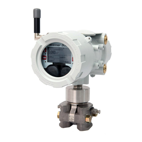
Figure 2.3—Wireless Scanner 3100 with MVT and direct-mount antenna; dimensions are shown in in. (mm) The installation of the antenna coupler, antennas, and antenna cable must meet the requirements shown in Figure 2.4 Figure 2.5, page Cameron supplies the following antenna and antenna cable options: • Direct-mount, right-angle antenna with N male connector •... -
Page 32: Fcc Radio Frequency Compliance
ANTENNA COUPLER (NO SEAL REQUIRED) PART NO. 2350765-01 (CSA - NORTH AMERICA) PART NO. 76533628 (ATEX) HAZARDOUS AREA Figure 2.4—Installation requirements for a direct-mount Cameron-supplied antenna ANTENNA COUPLER (NO SEAL REQUIRED) REMOTE ANTENNA PART NO. 2350765-01 (CSA - NORTH AMERICA) PART NO. -
Page 33: Ic Radio Frequency Compliance
Scanner 3100 EFM Section 2 The SmartMesh radio has been tested and found to comply with the limits for a Class B digital device, pursuant to Part 15 of the FCC Rules. These limits are designed to provide reasonable protection against harmful interference in a resi- dential installation. -
Page 34: Antenna Installation Options
2 in. or less. The supplied hardware includes two U-bolts, two toothed brackets, four lock washers and four nuts. Note If a 2-in. pipe with a 2 3/8-in. outside diameter is to be used, consider using Cameron’s 2-in. pipe mount hard- ware kit. To install the antenna, reference Figure 2.7... -
Page 35: Remote-Mount Antenna For Pipe Outside Diameters Of 2 3/8 Inches
Remote-Mount Antenna for Pipe Outside Diameters of 2 3/8 Inches Cameron’s optional pipe mount kit accommodates mounting the remote antenna to a 2-in. pipe with a 2 3/8-in. outside diameter. The hardware kit includes a stainless steel L-shaped bracket, two U-bolts, four U-bolt nuts, two stainless steel 5/16-18 bolts (3.25-in. -
Page 36: Table 2.2—Industry Standards For Meter Installation
Section 2 Scanner 3100 EFM Table 2.2—Industry Standards for Meter Installation Meter Type Standard Description Orifice Meter AGA 3, Section 2.6 Specifications for orifice meters (to include beta ratios) Installation requirements for orifice plates, meter tubes, flow conditioners, and thermometer wells This standard is also distributed under the following names: API MPMS Chapter 14.3, Part 2;... -
Page 37: Measuring Natural Gas Via A Differential Pressure Meter
Scanner 3100 EFM Section 2 Table 2.2—Industry Standards for Meter Installation Meter Type Standard Description Turbine AGA 7, Section 7 Installation of gas turbine meters to include flow direction, meter orientation, Meter meter run connections, internal surfaces, temperature well location, pressure... -
Page 38: Direct Mount To Orifice Meter Or Cone Meter
Section 2 Scanner 3100 EFM • β (diameter ratio) must be greater than or equal to 0.1 and less than or equal to 0.75. • Gauge lines should be of uniform internal diameter and constructed of material compatible with the fluid being measured. -
Page 39: Remote Mount To Orifice Meter Or Cone Meter
Verify that the meter is properly installed in the flow line (per manufacturer’s instructions). Bolt a flange-by-flange 5-valve manifold (as recommended by Cameron) to the Scanner 3100 MVT sensor. Locate the H and L markings on the MVT sensor body and position the MVT/manifold assembly so that the upstream side of the flow line can easily be connected to the sensor’s “High”... - Page 40 Scanner 3100 EFM Verify that the meter is properly installed in the flow line (per manufacturer’s instructions). Mount the Scanner 3100 to a 2-in. pipe using the mounting bosses on the side of the enclosure and a Cameron pole mount kit. See Pole-Mounting the Scanner 3100, page 30 for detailed mounting instructions.
-
Page 41: Measuring Natural Gas Via A Turbine Meter
To connect the Scanner 3100 to a turbine meter, perform the following steps: Verify that the flowmeter and magnetic pickup are installed in the flow line. Mount the Scanner 3100 to a 2-in. pipe using the mounting bosses on the side of the enclosure and a Cameron pole mount kit. See Pole-Mounting the Scanner 3100, page 30 for detailed mounting instructions. -
Page 42: Measuring Steam Via A Differential Pressure Meter
Section 2 Scanner 3100 EFM CAUTION Do not put the Scanner into operation until the valves are positioned properly so that pressure is supplied to both sides of the MVT. For instructions on proper valve positions, see Placing the Scan-... -
Page 43: Installation Procedure-Remote Mount To Orifice Meter Or Cone Meter
Scanner 3100 EFM Section 2 Hot Legs • Hot legs should be large diameter (1/2 in. recommended) • Hot legs should be as short as possible. If these sections must be more than 1ft in length, insulate them. • Elbows and bends should not form any traps in which liquid can accumulate. - Page 44 Section 2 Scanner 3100 EFM Pipe tee (can be used to fill cold legs) Condensate pot (pipe tee with blowdown valve attached) Long cold legs protect the sensor from extreme process temperatures Hot legs, insulated to within Cold legs connect to manifold...
- Page 45 Scanner 3100 EFM Section 2 Mount a set of pipe tees (which serve as condensate pots) typically on either side of the Scanner 3100 at an elevation above the process connections of the Scanner 3100 MVT (for proper drainage). They should be a considerable dis-...
-
Page 46: Measuring Liquid Via A Differential Pressure Meter
Section 2 Scanner 3100 EFM Measuring Liquid via a Differential Pressure Meter Best Practices To ensure measurement accuracy, ensure that the meter run complies with the following AGA 3 and ISO 5167 guide- lines, as applicable: • Do not place unit near vents or bleed holes that discharge corrosive vapors or gases. -
Page 47: Direct Mount To Orifice Meter Or Cone Meter
Scanner 3100 EFM Section 2 Direct Mount to Orifice Meter or Cone Meter A Scanner 3100 can be mounted directly to an orifice meter or cone meter for liquid measurement using a side-port MVT, a block manifold and two football flange adapters (Figure 2.13, page... -
Page 48: Remote Mount To Orifice Meter Or Cone Meter
MVTs. Contact a Cameron field representative for assistance. Verify that the meter is properly installed in the flow line (per manufacturer’s instructions). Mount the Scanner 3100 to a 2-in. pipe using the mounting bosses on the side of the enclosure and a Cameron pole mount kit. See Pole-Mounting the Scanner 3100, page 30 for detailed mounting instructions. - Page 49 Scanner 3100 EFM Section 2 Install the RTD assembly in the thermowell. Remove the plug from a conduit opening in the top of the Scanner 3100 enclosure, route the RTD assembly cable through the conduit opening and connect it to the terminal board. A wiring diagram for the RTD assembly is provided in Figure 3.6, page...
-
Page 50: Measuring Compensated Liquid Via A Turbine Meter
Section 2 Scanner 3100 EFM Make sure the shut-off valves in the tubing near the meter pressure taps are closed, and the meter is filled with process fluid. b. Open the equalizer and bypass/block valves on the block manifold. Make sure the vent valve is closed. -
Page 51: Performing A Manifold Leak Test
Scanner 3100 EFM Section 2 Performing a Manifold Leak Test A manifold leak test is recommended prior to operating any differential pressure meter into service. Check the manifold for leaks as follows: Verify that the instrument is approximately level and is properly connected to the pressure source. -
Page 52: Static Pressure Calibration And Verification
Section 2 Scanner 3100 EFM Click to apply the offset to the Scanner 3100, and exit the Maintenance mode. Save Note Zero offset values are cleared when a new calibration is saved. EQUALIZER EQUALIZER VENT BYPASS/ BYPASS/ BLOCK BLOCK Figure 2.16—Valve positions for zero offset... -
Page 53: Differential Pressure Calibration And Verification
Scanner 3100 EFM Section 2 EQUALIZER EQUALIZER VENT BYPASS/ BYPASS/ BLOCK BLOCK Figure 2.17—Valve positions for static pressure calibration To verify the static pressure, perform the steps described in steps 6 through 12 above, except instead of clicking the Cali- tab, click the tab. -
Page 54: Placing The Scanner Into Operation
Section 2 Scanner 3100 EFM EQUALIZER EQUALIZER VENT BYPASS/ BYPASS/ BLOCK BLOCK Figure 2.18—Valve positions for differential pressure calibration To verify the differential pressure, perform the steps described in steps 6 through 12 above, except instead of clicking the tab, click the tab. -
Page 55: Section 3-Wiring The Scanner 3100 Efm
Scanner 3100 EFM Section 3 Section 3—Wiring the Scanner 3100 EFM Field Wiring Connections WARNING: Do not connect/disconnect equipment or change batteries unless the area is known to be non- hazardous. The Scanner 3100 poses no hazard when opened in a safe area. - Page 56 Section 3 Scanner 3100 EFM Ground screws Ground screw Figure 3.2—External and internal ground screw locations Connect the flowmeter input wiring to TFM 1, TFM 2, or TFM 3, as required. Terminal Block Terminals TFM 1 7, 8, 9 TFM 2...
-
Page 57: Power Supply Wiring
Power Supply Wiring Internal Power Supply Cameron’s 7.2 V lithium battery packs provide reliable backup power when used with an external primary power supply. The Scanner 3100 supports up to two battery packs simultaneously. The battery compartment is located below the dis- play/keypad assembly and is readily accessible when the front cover is removed from the enclosure. -
Page 58: External Power Supply
Section 3 Scanner 3100 EFM Should the primary power supply fail, take the following precautions to maximize battery life: • Ensure calculation frequency is no greater than once per minute. • Ensure logging frequency (interval) is no greater than once per hour. -
Page 59: Input Wiring
Scanner 3100 EFM Section 3 Input Wiring Turbine Flowmeter Inputs TFM inputs 1, 2 and 3 on the terminal board provide the turbine flowmeter input signal generated by a magnetic pickup, enabling the Scanner 3100 to calculate and display instantaneous flow rates and accumulated totals. Wire as shown in Figure 3.5. -
Page 60: Analog Inputs
Section 3 Scanner 3100 EFM Analog Inputs The analog inputs (Figure 3.7), which can be configured for a 0 to 5 V, 1 to 5 V, 0 to 20 mA or 4 to 20 mA signal, can be used to receive readings from a pressure or temperature transmitter for use in any flow run. Alternatively, they can be used to log measurements from any device with a 0 to 5 V, 1 to 5 V, 0 to 20 mA or 4 to 20 mA output. -
Page 61: Digital Inputs-Contact Closure
Scanner 3100 EFM Section 3 Digital Inputs—Contact Closure The digital contact closure input (Figure 3.9, top) provides an input for use with any relay contact switch. DIO 1 through DIO 4 are optically isolated. DIO 5 and DIO 6 (Figure 3.9, bottom) are non-isolated. -
Page 62: Digital Inputs-Pulse
Section 3 Scanner 3100 EFM Digital Inputs—Pulse The digital pulse input (Figure 3.10) provides an input for use with any 3 to 30 VDC pulse-generating device. DIOs 1 through 4 (shown at left) are optically isolated. DIOs 5 and 6 (shown at right) are non-isolated. -
Page 63: Output Wiring
Scanner 3100 EFM Section 3 Output Wiring Analog (4 to 20 mA) Outputs The 4 to 20 mA output (Figure 3.12) provides a linear current output that can be configured to represent any parameter in the holding registers using the Scanner 3100 web interface. This output requires a two-conductor cable connected to a 9 to 30 VDC power supply (voltage required is dependent on loop resistance) and a current readout device located in the remote location. -
Page 64: Digital Outputs
Section 3 Scanner 3100 EFM Digital Outputs The standard Scanner 3100 supports six solid-state digital outputs that are configurable as pulse outputs, alarm outputs, conditional outputs, or programmed outputs using time of day or an output state as the trigger. -
Page 65: Communications
Scanner 3100 EFM Section 3 Communications RS-485 Communications The Scanner 3100 supports digital serial communications using EIA-RS-485 hardware with Modicon Modbus protocol. RS-485 communications are supported by three ports with a baud range of 300 to 115.2K. Ports 1, 2, and 3 can be used simultaneously, if desired, and all three ports are protected from high-voltage transients. -
Page 66: Ethernet Communications
Section 3 Scanner 3100 EFM Ethernet Communications An RJ-45 connector (Figure 3.1, page 55) provides the Ethernet communications required for accessing the web inter- face via a web browser and for transmitting data over two TCP ports. The TCP ports support Modbus TCP and Modbus- over-TCP protocols and can be configured individually (assigned to unique port numbers) using the web interface. -
Page 67: Section 4-Connecting To The Scanner 3100 Interface
Scanner 3100 EFM Section 4 Section 4—Connecting to the Scanner 3100 Interface To connect to the Scanner 3100 interface, you will need to establish a local area network between your computer (PC or laptop) and the Scanner using Ethernet cables and possibly, a router. An IP address will be assigned to the Scanner 3100 during this process. -
Page 68: Connection Options
Add the Scanner 3100 to an existing corporate network (contact your IT professional for assistance) – Create an ad hoc network using a wireless router (for locations without an external power supply, Cameron recommends the use of a portable router) –... -
Page 69: Ad-Hoc Wireless Router Connection
Important Cameron supports only select third-party portable wireless routers that are compatible with the Windows 7 operating system and are IEEE 802.11 compliant. Contact your local Cameron represen- tative for a list of supported routers. To establish the Scanner 3100’s connection to a laptop via a wireless router, obtain the following hardware: •... -
Page 70: Multi-Port Router Option
Section 4 Scanner 3100 EFM Select and click Start this connection automatically Next Click the “Wireless Communication” icon on the Quick Access tray at the bottom of the laptop screen. If you cannot see the icon, expand the Quick Access tray. -
Page 71: Installation
Scanner 3100 EFM Section 4 purchase. Note A user-supplied external 110/240 VAC, 50/60 Hz power supply is required to power the WiFi box. The WiFi box is pre-assembled and the router is pre-configured at the factory. Field wiring is limited to power connec- tions to the box and to the Scanner 3100 and an Ethernet connection to the Scanner 3100. - Page 72 Section 4 Scanner 3100 EFM U-bolt Integral mounting (1 of 2) bracket (1 of 2) Antenna cable Figure 4.2—WiFi box mounted on a 2-in. pole Bulkhead Mount To mount the WiFi box to a flat vertical surface, Dry-fit the WiFi box and mark screw locations using the outside holes on the top and bottom of the WiFi box inte- gral mounting brackets.
-
Page 73: Wiring The Wifi Box
Scanner 3100 EFM Section 4 Figure 4.3—(Left) Standard antenna mounting bracket for outside pipe diameters up to 2-in. and (right) alternate antenna mounting bracket for outside pipe diameters of 2.375-in. Wiring the WiFi Box WARNING: Before attempting any wiring, ensure that all power is disconnected. Failure to disconnect main service power to the WiFi box can cause severe personal injury, death, or substantial property dam- age. - Page 74 Section 4 Scanner 3100 EFM To wire the WiFi box for operation, perform the following steps: Open the door of the WiFi box and open the F1 and F2 fuse housings on the power block (Figure 4.5). Fuse F1 opens from the top. Fuse F2 opens from the bottom.
- Page 75 Scanner 3100 EFM Section 4 To free up space for pulling wires through the conduit port, unseat the terminal board by unscrewing the four Phillips screws holding it in place and gently pulling the board straight back to disconnect it from its connected header without bending pins.
- Page 76 Section 4 Scanner 3100 EFM Tighten the power supply cable connector. Verify that the F1 and F2 fuse housings on the power block are open (Figure 4.8, page 75). Wire the external power supply to the designated terminal blocks (H, N, GND) as shown in Figure 4.9.
-
Page 77: Connecting To The Scanner 3100
Shut off the laptop and restart it. If the modem is powered, but no wireless connectivity is detected on your computer or other browser-enabled device, it may be necessary to reset the Scanner 3100 IP address. Please contact Cameron technical support for assistance. - Page 78 Section 4 Scanner 3100 EFM This page intentionally left blank.
-
Page 79: Section 5-Display And Keypad Operations
Scanner 3100 EFM Section 5 Section 5—Display and Keypad Operations The Scanner 3100 display and keypad allows you to view the real-time measurements for up to 32 selected parameters, 5 at a time. By default, the parameters scroll continuously through the 5 fields provided (Figure 5.1). In a declassified or safe area, you can use the keypad to manually pace the display. -
Page 80: Table 5.1—Device Status Glyph Definitions
Section 5 Scanner 3100 EFM Table 5.1—Device Status Glyph Definitions Keypad Use. This glyph depicts the four keys positioned on either side of the LCD. Pressing a key on the keypad causes the corresponding key in the glyph to appear filled, verifying that the key is actuated. -
Page 81: Configurable Display Features
Scanner 3100 EFM Section 5 Table 5.1—Device Status Glyph Definitions Wireless Communications Status. The wireless transmitter is disabled. No mesh nodes are configured. At least one mesh node is configured but none are operational. One or more mesh nodes are configured and at least one is operational. -
Page 82: Message Display Mode
Section 5 Scanner 3100 EFM Message Display Mode You can force selected “high priority” parameters to be displayed only in the top field of the display by assigning a prior- ity status to these parameters (Figure 5.2). Parameters configured as “topmost” will always be... -
Page 83: Viewing Communication Settings
Scanner 3100 EFM Section 5 contained within the binary file loaded onto the Scanner 3100. The codes uniquely define the device firmware and soft- ware to ensure that the firmware has not been modified. Cover the right side of the LCD to stop automatic scrolling and enable manual pacing through the device parameters. - Page 84 Section 5 Scanner 3100 EFM This page intentionally left blank.
-
Page 85: Section 6-Scanner 3100 Efm Maintenance
Scanner 3100 EFM Section 6 Section 6—Scanner 3100 EFM Maintenance The Scanner 3100 is engineered to provide years of dependable service with minimal maintenance. Batteries require pe- riodic replacement, and battery life depends on (1) whether battery power is the primary or secondary power source, (2) the configuration settings of the Scanner 3100, and (3) ambient temperature conditions. - Page 86 Section 6 Scanner 3100 EFM To replace a Scanner 3100 lithium battery pack, Remove the cover from the enclosure (after securing the area per the warning on the previous page). Note Proceed carefully when connecting the battery packs to the plastic receptacles to avoid damaging the connector or bending pins.
-
Page 87: Section 7-Scanner 3100 Parts
1. Use of spare parts other than those identified by Cameron International Corporation voids hazardous area certification. Cameron bears no legal responsibility for the performance of a product that has been serviced or repaired with parts that are not authorized by Cameron. -
Page 88: Table 7.2—Wireless Components
* Recommended spare part ** For router adapters with other voltage ratings, contact Cameron. Table 7.2—Wireless Components Qty. Part No. -
Page 89: Electronics Replacement
The thermowell dimensions listed above refer to the maximum “U” dimensions that a probe will fit with a plastic bushing. Consult Cameron for sizing information if a union and nipple is to be used in place of a bushing. When using a bushing, select the shortest probe possible for a compact installation and best strength. - Page 90 Section 7 Scanner 3100 EFM Table 7.4—Scanner 3100 Circuit Board Replacements Qty. Part Number Description 50279704 Main Subassembly, includes Hardware Kit and SATA Cable (Field replacement in devices equipped with an MVT can result in accuracy degradation.) 2350508-01 Terminal Board...
-
Page 91: Appendix A-Lithium Battery Information
Federal law requires that depleted lithium battery packs be sent to a fully permitted Treatment, Storage and Disposal Fa- cility (TSDF) or to a permitted recycling/reclamation facility. Important Do not ship lithium battery packs to our factory. Cameron facilities are not permitted recycling/rec- lamation facilities. CAUTION Profiling and waste characterization procedures must be followed prior to shipping a lithium bat- tery to a disposal site. - Page 92 Appendix A Scanner 3100 EFM This page intentionally left blank.
-
Page 93: Appendix B-Ftp Downloads
Scanner 3100 EFM Appendix B Appendix B—FTP Downloads FTP downloads provide an alternative to the web interface download process and may be preferred for expediting down- loads, particularly if you have no other need to log into the web interface. FTP downloads can be performed with a router connection to the Scanner, or with a physical Ethernet cable connection between the PC/laptop and the Scanner. -
Page 94: Slave Device Archive Logs
Slave archive logs can also be downloaded locally from a Scanner 2000, 2100 or 2200 using ModWorX™ Pro software. Viewing and Sharing Downloaded Data Cameron’s Scanner Data Manager software opens the proprietary SDF files and provides an assortment of file sharing, conversion and reporting tools. See the Scanner Data Manager manual for more information. To download the Scan- ner Data Manager software and user manual, visit Cameron’s Measurement website at... -
Page 95: Appendix C-Firmware, Configuration, Scanner Logic, And Modbus Register Map Uploads
Register Map Uploads Using Cameron’s ScanMap software, a user can create a set of user-defined Modbus register maps (.pmap) for custom- izing Modbus communications protocols. A .pmap file can be uploaded to a Scanner 3100 using the Scanner 3100 web interface or the ScanFlash software utility. -
Page 96: Scanflash Upload
To upload a register map file via the ScanFlash utility, follow the upload instructions under ScanFlash Upload, page C-2. ScanFlash Upload Important To download ScanFlash software, visit Cameron’s Measurement website at http://www.cameron. choose CAMERON Flow Computer Scanner 3100, and click the link for the slb.com/flowcomputers,... - Page 97 Scanner 3100 EFM Appendix C Enter your user name and password for accessing the Scanner 3100 web interface. You must have the appropriate user access level to proceed. See the “Important” note above. Click to confirm the connection and identify the current firmware version. The button will turn blue while the Verify utility attempts to communicate with the Scanner.
- Page 98 Appendix C Scanner 3100 EFM This page intentionally left blank.
- Page 99 WARRANTY - LIMITATION OF LIABILITY: Seller warrants only title to the products, software, supplies and materials and that, except as to software, the same are free from defects in workmanship and materials for a period of one (1) year from the date of delivery. Seller does not warranty that software is free from error or that software will run in an uninterrupted fashion.
Need help?
Do you have a question about the Scanner 3100 EFM and is the answer not in the manual?
Questions and answers