Table of Contents
Advertisement
Quick Links
NU F L O™
Scanner
2000 microEFM
®
QuickStart
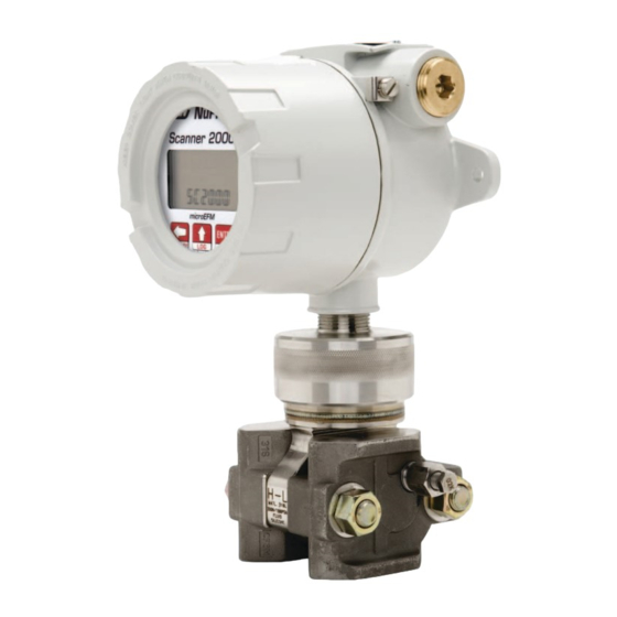
Installing the Scanner 2000
H L
H L
Direct Mount
To install the Scanner 2000 microEFM using a direct mount to
an orifice or cone meter run, perform the following steps:
1. Determine the best location for the Scanner 2000.
a. For horizontal meter runs, locate process connections at
the top of the line, and mount the Scanner 2000 above
the pressure connections at the pipe.
b. For vertical meter runs, make sure pipeline flow is up-
ward.
2. Locate the H and L markings on the Scanner 2000 transmit-
ter designating high-pressure and low-pressure ports, and
connect a valve manifold (if desired) to the transmitter.
3. Connect the orifice flanges to the Scanner 2000/manifold
assembly, matching the upstream tap to the high-pressure
manifold port and the downstream tap to the low-pressure
manifold port.
ADJUSTABLE HEAD DESIGN.
When the sensor is oriented ap-
propriately for pressure connec-
tions, the position of the Scanner
display may need to be adjusted.
To change the orientation of the
head, loosen the set screw in the
MVT adapter, rotate the head
no more than 180 degrees and
tighten the set screw.
Flow
Set screw
Remote Mount
To install the Scanner 2000 microEFM remotely from the
flow run, perform the following steps:
1. Mount the Scanner to a flat, vertical surface, or bolt
to a 2-in. pipe using optional pole-mount hardware.
2. Install process tubing between the orifice run and
the manifold, making sure that the upstream pres-
sure tap is connected to the high-pressure manifold
port and the downstream pressure tap is connected
to the low-pressure manifold port. Slope all piping
at least 1-inch per linear foot to avoid trapping
liquid.
3. Use a suitable compound or tape on all threaded
process connections.
4. Position all shutoff and bypass valves so they are
accessible from the front of the instrument.
5. Check the manifold for leaks.
POLE-MOUNT OPTION.
An optional pole mount kit
(Part No. 9A-30028004)
allows the Scanner 2000 to
be mounted to a 2-in.
vertical or horizontal pipe.
The kit includes a mounting
bracket, two U-bolts and
screws for connecting the
bracket to the Scanner 2000
enclosure.
Part No. 30165024, Rev. A
Advertisement
Table of Contents

Related Manuals for Cameron NUFLO Scanner microEFM 2000


Summary of Contents for Cameron NUFLO Scanner microEFM 2000
- Page 1 NU F L O™ Part No. 30165024, Rev. A Scanner 2000 microEFM ® QuickStart Installing the Scanner 2000 Flow Direct Mount Remote Mount To install the Scanner 2000 microEFM using a direct mount to To install the Scanner 2000 microEFM remotely from the an orifice or cone meter run, perform the following steps: flow run, perform the following steps: 1.
- Page 2 Wiring the Scanner 2000 EXTERNAL POWER INPUT 6 TO 30 VDC POWER SUPPLY SCANNER 2000 TURBINE INPUT Main Circuit Board PN: 30160010 TURBINE BLACK BATTERY MAGNETIC PICKUP RTD INPUT Field wiring enters the Scanner 2000 microEFM through either of two ¾-in.
- Page 3 Keypad Configuration & Controls CONTROL THE PARAMETER DISPLAY... Press the LEFT ARROW (DISPLAY) button to manually advance the display of param- Remove the instrument cover to access the keypad. Each of the three keys are used for eters in the LCD window. configuration and operation.
- Page 4 Navigating the ModWorX Pro Interface Main Display Screen Dedicated button for quick and easy downloads Four task-based menus simplify navigation The Scanner 2000 installation CD provided with the instrument loads the ModWorX Pro interface software for configuring and operat- ing the Scanner 2000. The Main Display screen (at left) is the control center for the Scanner 2000 and provides quick and easy access to the most commonly...
- Page 5 Calibrate Inputs Menu From the Calibrate Inputs menu, a user can calibrate differential pressure, static pressure, and process temperature. The user can load a factory calibration, load a previous calibration, or enter new calibration points. Click Acquire Point to enter a new Select the task you calibration point and enter the applied want to perform.
- Page 6 Maintain Flow Run Menu From the Maintain Enter new parameters in the fields Select the task you Flow Run menu, a provided. want to perform. user can change an Or click on Copy From Current to load current orifice plate size, parameters.
- Page 7 Configure Menu From the Configuration The Configure Flow Run 1 screen below menu (right), a user can access shows configuration settings for an every setting required to AGA-3 gas run. Required parameters will perform the initial setup for vary, depending on the flow calculation the Scanner 2000.
- Page 8 Download Screens To download data, simply press the Download button and select the range and type of files to be downloaded. Daily Click on the red Download button to and interval logs can be viewed download log data. or printed as a table or a trend graph.
Need help?
Do you have a question about the NUFLO Scanner microEFM 2000 and is the answer not in the manual?
Questions and answers