Sign In
Upload
Manuals
Brands
Cameron Manuals
Measuring Instruments
NUFLO MC-III
Cameron NUFLO MC-III Manuals
Manuals and User Guides for Cameron NUFLO MC-III. We have
1
Cameron NUFLO MC-III manual available for free PDF download: User Manual
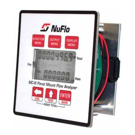
Cameron NUFLO MC-III User Manual (120 pages)
Panel Mount Flow Analyzer
Brand:
Cameron
| Category:
Measuring Instruments
| Size: 4.67 MB
Table of Contents
Table of Contents
3
Section 1-Introduction
7
Operation
7
LCD Display
10
Keypad
10
Interface Software
11
Power Supply
12
Multipoint Linearization
12
Gas Volume Correction
12
Input Options
12
Output Options
12
Flow Log Archival
12
Event Log Archival
13
Password-Protected Security
13
Commonly Used Functions
13
Reading Totals
13
Saving Totals to Memory
13
Resetting the Total
13
Viewing Daily and Hourly Logs
14
Saving and Uploading Configuration Files
14
Exporting Log Data
14
Saving Log Data in a Report
14
Section 2-Installation
15
Flow Meter/Magnetic Pickup Installation
15
MC-III Installation
15
Field Wiring Connections
17
Power Supply Wiring
18
Internal Power Supply
18
External Power Supply
18
Input Wiring
19
Turbine Flow Meter (TFM) Input
19
Pulse Input
19
Remote Reset Input
20
Output Wiring
21
Pulse Output
21
Analog (4-20 Ma) Rate Output
21
Flow Meter Frequency Output
22
RS-485 Output
23
Section 3-Configuration and Operation Via Keypad
25
Entering a Calibration Factor
26
Entering a Calculated Divisor
27
Setting Input Type and Sensitivity
28
Configuring the Total Display
29
Configuring the Rate Display
30
Configuring the 4-20 Ma Rate Output
31
Configuring the Pulse Output
34
Entering the Slave Address
35
Entering the Baud Rate
35
Section 4-Configuration and Operation Via Software
37
Installing the Software
37
Accessing Help
37
Connecting to the Software
38
Automating Functions on Software Startup
39
Changing Autorun Settings
40
Express Connect Option
40
Changing the Communications Port
41
Software Connection in Multi-Device Network
41
Setting Log Download Preferences
43
Configuring the MC-III Panel Mount
44
Configuration Wizard
46
MC-III Main Screen
48
Buttons and Tools
49
System Setup
52
Time/Date Synchronization
52
Contract Hour
52
LCD Contrast Adjustment
52
Security Setup
53
Firmware Version Number
53
Serial Number
53
Communications Port
54
Slave Address
54
Baud Rate
54
Bus Delay
55
Bus Timeout
55
Software Communication Options
55
Wellsite Information
56
Turbine Input
57
Volume Display
57
Rate Display
57
Input Type/Sensitivity Configuration
58
Cut-Off Thresholds
58
Calculation Period
58
K-Factor Entry
59
K-Factor Units
59
K-Factor Type
59
K-Factor Backup
60
Gas Volume Correction (Supercompressibility Calculation)
61
4-20 Ma Output
63
Enabling 4-20 Ma Output
65
4-20 Ma Output Testing
65
Pulse Output
67
Configuring Pulse Output
67
Pulse Output Testing
68
Saving and Uploading Configuration Files
69
Saving a Configuration File
69
Uploading a Configuration File
70
Advanced Access
72
Section 5-Flow Logs and Event Logs
73
Auto-Save Log Formats
74
Log Directory and Filenames
74
Flow Archive
75
Downloading Flow Logs
75
Viewing Trend Charts
77
Printing/Saving a Report
77
Viewing a Saved Report
79
Exporting Flow Logs
81
Event Archive
82
Downloading Event Logs
83
Printing/Saving a Report
84
Exporting Event Logs
84
Section 6 - MC-III Panel Mount Maintenance
87
Lithium Battery Replacement
87
Reinstalling the Velcro Strap
88
Circuit Assembly Replacement
89
Firmware Update
91
Spare Parts List
92
Communication Cable Assemblies
92
Signal Cable Assemblies
92
Magnetic Pickups
92
Appendix A-Software Program Options
93
General Options
93
Autorun Options
94
Communications Options
95
Express Connect Option
95
Auto-Negotiate Option
96
Enable Auto-Negotiated Baud Rate Option
96
Request-To-Send (RTS) Line Option
96
Enable Modbus Address Support for Firmware Versions 1.06 through 1.08
96
Timing Parameters
96
Downloading Options
97
Advanced Options
98
Clear EEPROM
98
Automatic Data Logging
98
Appendix B-Lithium Battery Information
99
Lithium Battery Disposal
99
Transportation Information
99
Material Safety Data Sheet
99
Appendix C-Communications Protocol
101
Introduction
101
Supported Commands
101
Data Types
101
Registers
102
System Configuration
102
Product Code (Register 1000
104
Firmware/Register Table Version Numbers (Registers 1001, 1002
104
Manufacture Date/Sales Date (Registers 1003, 1004
104
Slave Address (Register 1009
104
Baud Rate (Register 1010
104
Real Time
105
Input Configuration
105
Output Configuration
108
Holding Registers (16-Bit Mode
109
Base Units/Configured Units
111
Conversion Factors
111
Polling Registers
111
Pointer/Daily/Event Pointer (Registers 17001 through 17006
111
Real Date (Registers 17007, 17008
111
Real Time (Registers 17009, 17010
112
Totals
112
Pulse Output Pulses (Register 17077
112
Analog Output Current (Register 17079
112
Calculated K-Factor (Register 17081
112
Holding Registers (32-Bit Mode
112
Control Register
114
Wellsite Parameters
115
Log Data
115
Enron Registers
116
Enron Hourly/Daily Record Format
116
Enron Event Record Format
116
Reset Status
117
Log Capacity
117
Advertisement
Advertisement
Related Products
Cameron NUFLO MC-III EXP
Cameron NuFlo MC-II
Cameron NUFLO EZ-IN Series
Cameron NUFLO Scanner 2000 microEFM
Cameron 351
Cameron 352
Cameron 353
Cameron Barton 199
Cameron BARTON 289A
Cameron LEFM 200
Cameron Categories
Control Unit
Measuring Instruments
Industrial Equipment
Switch
Transmitter
More Cameron Manuals
Login
Sign In
OR
Sign in with Facebook
Sign in with Google
Upload manual
Upload from disk
Upload from URL