TDT Medusa4Z User Manual
Hide thumbs
Also See for Medusa4Z:
- Quick start manual (2 pages) ,
- Hardware reference manual (10 pages)
Table of Contents
Advertisement
Quick Links
Advertisement
Table of Contents
Troubleshooting

Subscribe to Our Youtube Channel
Related Manuals for TDT Medusa4Z


Summary of Contents for TDT Medusa4Z
- Page 1 ABR User Guide Medusa4Z Amplifier Updated 2021-03-24...
- Page 2 The information contained in this document is provided "as is," and is subject to being changed, without notice. TDT shall not be liable for errors or damages in connection with the furnishing, use, or performance of this document or of any information contained herein.
-
Page 3: Table Of Contents
Table of Contents | 3 Table of Contents ABR Testing with the RZ6 and Medusa4Z ABRs - from Set-up to Data Collection The Subject Expected Hearing Range Age-Related Effects on Hearing Anesthesia Considerations Your Test Area Grounding Enclosure Considerations Speaker Placement... - Page 4 Wrapping up Noise Exposure Key elements of noise exposure: Hardware Requirements: Setting Up Signal Generation in RPvdsEx Preparing a Suitable Enclosure Working with Multiple Subjects Upgrading from RA4PA to Medusa4Z Hardware Setup Software Updates Hardware Updates Software Configuration Changes Wrapping up...
-
Page 5: Abr Testing With The Rz6 And Medusa4Z
ABR Testing with the RZ6 and Medusa4Z ABRs - from Set-up to Data Collection This guide is primarily intended for researchers who are new to collecting ABRs using a TDT RZ6 system with Medusa4Z preamplifier and BioSigRZ software. It brings together targeted... - Page 6 ABR Testing with the RZ6 and Medusa4Z | 6 • Modifying the stimulus parameters • Conducting noise exposure experiments ABR Overview An ABR is a synchronous neural response to an auditory stimulus. ABR testing can be used to estimate hearing sensitivity. The ABR is an early potential, occurring shortly after stimulus onset, and is typically in the 1 - 2.5 microVolt range, so small that it can be masked by the...
- Page 7 Recordings should be performed in a shielded enclosure that has been set-up to minimize noise interferences. The TDT system for ABR recording is designed to minimize noise at every step, beginning with an optically isolated, battery powered Medusa4Z preamplifier. This device digitizes the biologic responses right in the enclosure.
- Page 8 ABR Testing with the RZ6 and Medusa4Z | 8 Typical System Using TDT's RZ6 Processor and Medusa Preamplifier What you'll need: Windows computer (WS4 shown) Optibit interface (installed in computer) TDT Drivers (software installed on computer) BioSigRZ (software installed on computer)
-
Page 9: The Subject
The Subject | 9 The Subject Planning or setting up your ABR experiment must begin with an understanding of the subject's normal hearing range and factors that might have an effect on its response or recording. ABRs have been measured for many species. In this guide, we'll focus on the three most common species used in ABR experiments and screening protocols: mice, rats, and guinea pigs. -
Page 10: Age-Related Effects On Hearing
The Subject | 10 Age-Related Effects on Hearing Many lab subjects experience hearing loss due to age. The rate of loss varies across species and strains. This effect has been observed as early as 12 weeks in mice. Anesthesia Considerations Two types of anesthesia protocols are typically used for ABR testing. -
Page 11: Your Test Area
Your Test Area | 11 Your Test Area The small size (1 - 2.5 microVolt @ 90dB stimulation) of typical ABR response signals makes it especially important to minimize electrical noise in the test area and to ensure all conditions are carefully controlled during testing. -
Page 12: Speaker Placement
Your Test Area | 12 Speaker Placement Most enclosures have some amount of acoustical reflection or interference during open field stimulus presentation. The effects will vary depending on the size of the enclosure, the angle at which the speaker is positioned, and the materials used or added for sound dampening. To minimize the effects of distortion or interference, position the stimulus speaker on the same plane as the subject's ear and set at an angle from the sides of the enclosure. - Page 13 Your Test Area | 13 Important It is critical that you place the heat pump and all associated electrical connections outside the Faraday cage when using this type of pad.
-
Page 14: The Test Equipment
The care used in setting up your test area must also be taken when selecting and setting up your test equipment. TDT's ABR system is part of a modular experiment platform. Each module in the system is designed for exceptional signal fidelity, precise timing, low noise, and ease of use. -
Page 15: Medusa4Z Bioamp
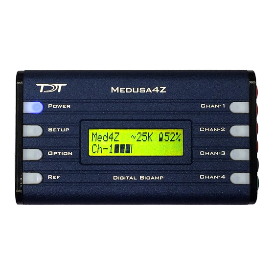
The supplied battery charger must NOT be connected or inside the enclosure when running experiments. To protect the battery, do not leave the Medusa4Z on the charger for an extended period of time (1+ week). By default the Medusa4Z will boot up as shown above. A few changes must be made to the... -
Page 16: Speakers
Caution Use the POWER button on the top of the Medusa4Z to turn it on and off. There is an ON/OFF (RESET) switch on the side which completely disconnects the battery and loses all user settings. You should only use the ON/OFF (RESET) switch if storing the Medusa4Z for an extended period of time. -
Page 17: Rz6 Signal Processor
The Test Equipment | 17 For Open Field experiments, place the speaker 10 cm from the subject. Be sure to position it to the side of the subject, in line with the ear, NOT in front of the subject. For more information on the MF1 speakers and full system specs, see the System 3 Manual. - Page 18 Stimulus Output The RZ6's can generate a stimulus in the frequency range of DC - 88 kHz and is well suited for standard ABR testing. A built-in stereo power amplifier drives the stimulus signals through TDT's MF1 multi-function speaker via the BNC labeled Out-A.
- Page 19 V-shaped groove up. The green LED next to the Optical In port on the RZ6 will illuminate when the preamplifier is connected and both devices are powered on. This indicates that the Medusa4Z is properly time-locked with the RZ6.
- Page 20 Displaying and working with data during and after acquisition. If you use TDT's WS4 computer, the optical interface and BioSigRZ software are pre-installed. If you use your own PC, you'll need to install the interface card and BioSigRZ software yourself.
-
Page 21: Biosigrz Software
BioSigRZ Software | 21 BioSigRZ Software BioSigRZ software is streamlined and optimized for ABR and DPOAE screening. The software provides a simplified interface for selecting a stimulus and configuring how the biological response will be recorded and processed. Typically, ABR experiments use click and/or tone stimuli. Click ABRs A click (square wave) is a broadband signal that stimulates a larger frequency range with each stimulus presentation. -
Page 22: Tone Abrs
When the software is installed, out-of-box experiment files for both types of ABRs are stored at: . The default values used in the pre-configured experiments C:\TDT\BioSigRZ\Configs\ABR are set to values suited to typical experiments. Your protocol or circumstance may differ from these values but these will work as an example or a starting point in most cases. -
Page 23: The Stimulus Settings
RZ6 fiber optic port. A total of 512 responses will be averaged at each level. C:\TDT\BioSigRZ\Configs\ABR\Root_ToneAbr.acf A five millisecond, single-channel cosine-squared gated tone will be presented 21 times per second at the following frequencies: 4 kHz, 8 kHz, 16 kHz, 24 kHz and 32 kHz. - Page 24 MF1 speaker. You will need to copy that file to the following directory: . After the file has been copied to this directory you will be able to \TDT\BioSigRZ\TCF select it from a list in the Stimulus Setup. You can also make your own .tcf calibration...
-
Page 25: The Acquisition Settings
BioSigRZ Software | 25 The Acquisition Settings The default acquisition settings should be fine to begin, but you may eventually want to make adjustments. The acquisition settings dialog boxes can be opened by clicking Setup → Acquisition. The setting notes below provide information about each setting. - Page 26 The typical range is 256 -- 1024 averages. Note: Subjects with hearing loss often require more averages than normal hearing subjects. Gain Why and Where? The Medusa4Z has unity gain and the BioSigRZ Acquisition setup gain should be set to 1x.
-
Page 27: Running The Experiment
TDT can provide an electrode kit with suitable needle electrodes for ABR testing. One electrode is required for each channel, plus one for Ground and one for Reference. The electrodes should be inserted just under the skin and connected to the appropriate input on the Medusa4Z. Correct placement is essential for acquiring good data. -
Page 28: Check Impedance
Running the Experiment | 28 Check Impedance The Medusa4Z includes built-in impedance checking. Impedance is a measure of resistance from electrode to ground. High impedance can result in lower response signals or no signal at all. After inserting electrodes, run an impedance check for the subject to verify a good insertion and working electrodes. -
Page 29: Begin Experiment
Running the Experiment | 29 Note Startling the subject with a loud clap or loud noise is not a rigorous enough way to check sedation. A subject may not respond to clapping even when only partially sedated. Also, a test subject with hearing loss may not respond regardless of sedation level. -
Page 30: Modifying The Stimulus Schedule
Running the Experiment | 30 To begin data averaging: Click the Begin button. A Subject Information window opens. Information entered here is stored with the data in the response record file. Enter any subject information and click OK. You are now in Averaging Mode. The first stimulus is repeatedly presented and the ABR response data is acquired and included in the running average until the desired number of responses has been collected at that level. -
Page 31: Termination
Running the Experiment | 31 Running Avg This view displays the current running average. EEG Plot This view lets you see the last incoming EEG waveform. The signal displayed is not averaged, so sudden/ temporary anomalies will be visible. If the waveform jumps, for example, it may indicate that the subject is awake. - Page 32 Running the Experiment | 32 To halt stimulus presentation: • Click Stop. To run the experiment again: Click Begin. Enter the new subject information.
-
Page 33: Data And Export
Data and Export | 33 Data and Export Viewing data in the BioSigRZ plots and worksheet. History Plot In averaging mode, BioSigRZ acquires data and calculates a running average. Data will be acquired until enough records have been gathered to compute the final averaged signal. At that time, the averaged signal will be appended to the end of the History Plot, the SGI will be incremented, a new stimulus signal will be generated according to the current stimulus parameters, and a new average will be computed. -
Page 34: The Worksheet
Data and Export | 34 The Worksheet The worksheet provides you with several basic functions. It allows you to graphically organize acquired data and perform mathematical and visualization manipulations of the acquired data directly in BioSigRZ. The Worksheet is located to the right of the History plot. Waveforms can be copied from the Worksheet and pasted to other applications for report writing or by choosing to generate a report, you may output data for use by other applications. - Page 35 Data and Export | 35 To export the trace data, check the box next to Data Samples. If you wish to further customize the export, click the check boxes or radio buttons to toggle on/off the desired options. The settings shown are the typical/ recommended export settings. Type a report title in the Title field.
-
Page 36: Troubleshooting
20%. If either of these noise tests don't give the expected results, please contact TDT Tech Support support@tdt.com. These simple tests are a good way to identify noise issues before you being collecting data, they are also good tests to run after any system changes or after the system is moved or maintained in any way. -
Page 37: Diagnosing Noise Issues
Here are a few common sources of noise: The charger for the Medusa4Z was left plugged in Always disconnect the preamplifier from the charger and rely on the battery during recordings. No high voltage lines should be used inside the Faraday cage. Also disconnect the charger from the wall. -
Page 38: Troubleshooting On-The-Fly
They can become bent or corroded. Try using another electrode. If the noise disappears, the age or cleanliness of the problem electrode may have been the culprit. The Medusa4Z preamplifier battery is at the end of its charge A low battery state may cause poor recording. -
Page 39: Getting Help
Noisy signal Cause: A noisy environment. Run a saline test as described above. Getting Help If you are unable to diagnose the noise problem, contact TDT for assistance at support@tdt.com or +1.386.462.9622. When you contact us be prepared to answer questions such as, what frequencies you're testing, what subject and anesthetic you're using, and when the system was last calibrated. -
Page 40: Calibration
TDT MF1 magnetic speaker, you may choose to calibrate less often. If you are using a more specialized speaker, like the TDT EC1 or ES1 electrostatic speakers, you may choose to calibrate more often. If you are new to collecting ABR data,... -
Page 41: Hardware Setup
Calibration | 41 Hardware Setup To calibrate your system you should have everything set-up as you will have it setup for your experiment, with the exception of the subject. During calibration you will place a calibration microphone with a flat response in the band of interest in the place of the subject. The Amp/ BYP switch on the front of the RZ6 must be set in the 'Amp' position, and the Gain knob should be set to 40dB to start. - Page 42 Calibration | 42 Closed-Field Calibration Setup Possible coupler materials: Eartip Putty...
-
Page 43: Tone Calibration
This file is part of the BioSigRZExamples.zip zipped example folder, which can be downloaded from the TDT website. Download and extract the zipped files to: C:\TDT\BioSigRZ\RCX To use this circuit there are a few steps required for setup: Connect your Calibration Microphone to the In-A port on the RZ6. - Page 44 C:\TDT\BioSigRZ\SIG\Click.sig To open the SigGenRZ stimulus design software (included with BioSigRZ), click the Windows Start menu, click All Programs, click TDT Sys3, click SigGen Solutions, and then click SigGenRZ. This program can be used to edit stimulus files.
- Page 45 Calibration | 45 To open the standard click stimulus file, click File, click Open, browse to: C:\TDT\BioSigRZ\SIG\Click.sig Then click Open. On the main toolbar, click Modify, and then click Signal. In the Signal Parameters dialog box, enter the voltage and the corresponding dB level in the Calibration area, and then click OK.
-
Page 46: Testing Speakers And Microphones
The test circuit, , is part of the BioSigRZExamples.zip zipped SpeakerMicTest.rcx example folder, which can be downloaded from the TDT website. Speaker Test If you suspect that your speakers may not be functioning correctly, download and extract the zipped files to: C:\TDT\BioSigRZ\RCX Then double-click the SpeakerMicTest.rcx... - Page 47 Calibration | 47 To use this circuit there are a few steps required for setup: Connect your speaker to Out-A. RZ6 with MF1 Speaker To test your speaker: Click the Compile, Load, Run button on the toolbar. You should be able to hear a tone from the speaker.
- Page 48 Calibration | 48 RZ6 Open Field Calibration Setup...
- Page 49 Calibration | 49 You should be able to see a sine wave in the graph. You may need to adjust the scale using the green arrows on the sides of the graph. Click the Stop button again to stop the test.
-
Page 50: Sound Chamber Fundamentals
Sound Chamber Fundamentals | 50 Sound Chamber Fundamentals Reflections and interference inside of a sound chamber can distort the stimulus frequency or have an undesirable effect on the stimulus level. This section provides supplemental information on these issues and correctly setting-up your sound chamber. Reflections and Interference Sound waves are a mechanical force in which pressure is used to transmit energy through a physical medium. - Page 51 Sound Chamber Fundamentals | 51 Figure 2 - The summation of signals during constructive interference (left), partial interference (middle), and fully destructive interference (right). The level of interference is based on the frequency-specific phase delay, which is based on wavelength and distance of travel for the primary and reflected signals. Figure 3 - A standing wave that is present at the subject's ear when the reflection returns Constructive and destructive interference is caused by standing waves and their reflections.
-
Page 52: Ways To Reduce Reflections And Interference
Sound Chamber Fundamentals | 52 c (m/s) f (Hz) λ (mm) ∆ (mm) λ/4 343.2 4000 85.8 21.45 343.2 8000 42.9 10.725 343.2 16000 21.45 5.3625 343.2 32000 10.725 2.68125 Ways to Reduce Reflections and Interference To reduce reflections and interference: Increase the distance of travel for the reflections by changing the angle of incidence. If the angle of incidence is near a corner but not focused directly at a corner, the reflections will bounce off both walls and scatter throughout your chamber rather than bounce off one wall before converging at the center of the chamber. - Page 53 Sound Chamber Fundamentals | 53 Important The external shell is metallic and tied to earth ground, which doubles as a Faraday cage that will shield against electromagnetic radiation. Figure 5 - An example of a good sound chamber The floor and walls in Figure 5 are covered in soft, absorbing surfaces (1.75 inch foam padding) with significant damping power.
- Page 54 Sound Chamber Fundamentals | 54 directly back into the subject's ear. Second, the floor is a hard reflective surface that offers little to no damping. Figure 7 - An example of a bad sound chamber. Figure 7 is also incorrect because the speaker is aligned orthogonal to the wall, which also provides a direct reflective path back to the subject's ear.
-
Page 55: Configuring Mf1 For Closed Field
Configuring MF1 for Closed Field | 55 Configuring MF1 for Closed Field MF1 Closed Field Speaker Assembly Diagram Important Closed Field Adapter, Tip, and CF Line Filter used only for Closed Field Configuration! To configure the MF1 for closed field operation: Ensure Black O-ring is in place on back of CF Adapter, as shown. - Page 56 Configuring MF1 for Closed Field | 56 Attach the CF Adapter to the front of the speaker using three of the provided ¼ x 4-40 hex screws. Speaker with CF Adapter 3mm Tube Tip with Blue O-Ring Ensure the blue O-ring is in place at the base of the desired tip, as shown. Insert the tip into the groove on the CF adapter.
- Page 57 Configuring MF1 for Closed Field | 57 Back of Speaker (shown with included stand) Connect the MF1 to the amplifier using the RCA cable (with CF filter attached). For more information on the MF1 Speaker, see the System 3 Manual.
-
Page 58: Modifying The Stimulus
Modifying the Stimulus | 58 Modifying the Stimulus When the stimulus is defined, a complete list of signal parameters and variables are added to the BioSigRZ file. During stimulus presentation, the values of the variables change as a function of the SGI. This is called the stimulus schedule. You may wish to present a subset of the current stimulus schedule. -
Page 59: Modifying Variables
Modifying the Stimulus | 59 techniques, such as click, SHIFT-click, and CTRL-click. You can also choose to 'Do Odd' or 'Do Even', using buttons in the dialog box. When no SGIs are selected, BioSigRZ will present the entire stimulus schedule. Otherwise, BioSigRZ will present only the selected SGIs. Modifying Variables The variables can also be modified to meet your needs. - Page 60 Modifying the Stimulus | 60 Another commonly modified variable is the Gate Time for tone stimuli. Typical ABR gate times are 0.2 ms - 2 ms. Note Changing the gate time will change the size and shape of the response. Important The changes will only be saved in the configuration file, if the Lock SigGen Files check box is selected in the Stimulus Setup dialog bog.
-
Page 61: Customizing The Stimulus
To open the signal file you wish to modify: Click the Start button on the Windows taskbar, point to Programs, point to TDT Sys 3, and click SigGenRZ. Select Open from the File menu. - Page 62 Modifying the Stimulus | 62 Click the desired file name. Click OK. To save the file with a new name: Select the signal by clicking anywhere in the signal window. Choose Save As from the File menu. The Save As dialog box will be displayed. Type a new name for the signal and click OK.
- Page 63 Modifying the Stimulus | 63 In the Edit Signal Segment window, you'll find a variety of Windowing/Gating and other parameters. Gate Type From the Gate Type box, you can select a variety of gating or windowing functions, including: • Cos2 (10% - 90%) •...
-
Page 64: Suggested Stimulus File Changes
Modifying the Stimulus | 64 Suggested Stimulus File Changes In SigGenRZ, we supply a tone example called TonePip.sig. For mouse models, most customers like this as a starting point with two edits: Most mouse researchers find that the best responses are achieved with a 2-4 ms stimulus. -
Page 65: Wrapping Up
Modifying the Stimulus | 65 Wrapping up Before running any subjects with any ABR system, we recommend running a saline test. Only when the saline test looks good should you proceed to test with a subject. -
Page 66: Noise Exposure
Microphone and microphone amplifier (for calibration and testing enclosure) PC for experiment control When considering your hardware set-up, the first question to ask is what level sound you will be using. The TDT amplifiers and speakers are not intended for delivering sound greater than 100... -
Page 67: Setting Up Signal Generation In Rpvdsex
Studio, RPvdsEx, files. BioSigRZ and all other TDT software use RPvdsEx files behind the scenes to control TDT hardware. You will use this same software to deliver noise exposure. The RPvdsEx is a nuts and bolts tool with virtually limitless flexibility, but it wasn't really designed for running experiments. - Page 68 Tone RZ6_TimedTone_Calibrated.rcx These files are included in the BioSigRZ Examples folder found at: http://www.tdt.com/files/examples/BioSigRZExamples.zip After you have downloaded and extracted the folder, choose the file that is right for you and double-click it to run RPvdsEx and open the file.
- Page 69 Noise Exposure | 69 Random Noise Generation Circuit Working with Circuit Components This circuit is configured for you, but you will need to change the properties of some of the components.
- Page 70 Noise Exposure | 70 Circuit Segment To modify the properties of any component, double-click it and enter a new value in the properties dialog that is displayed and then click OK. To create a link, double-click an output port on a component, then click the input port on the next component in the circuit.
- Page 71 These components generate the filter coefficients used by the Biquad filters. To set the filters, modify the corner frequencies (Fc) in the ButCoef components as needed. The TDT System outputs a voltage. To ensures the output voltage is calculated correctly for the desired dB results, you need to calibrate the system.
- Page 72 Noise Exposure | 72 Double-click the first ConstF component and enter the microphone amplification level indicated by the microphone Gain knob setting on the face of the RZ6. Click OK. Important The microphone amplification switch on the RZ6 front panel must be set to AMP. Using the microphone sensitivity provided by the manufacturer, determine the calibration microphone voltage (usually listed on spec sheet in millivolts per Pascal).
- Page 73 Important TDT devices are limited to ± 10 V. If the calibration results in a voltage outside this range, your stimulus will be clipped and distorted. If this becomes and problem, you need a more sensitive speaker or a more powerful amplifier.
-
Page 74: Preparing A Suitable Enclosure
Noise Exposure | 74 To set the tone frequency: • Double-click the ConstF component, set the desired frequency in Hz, and click OK. Then run the circuit as explained above. Preparing a Suitable Enclosure Noise exposure is performed inside a chamber to protect the researcher's hearing. You will also need an enclosure inside the chamber to limit the movements of the agitated subject and ensure it is positioned near the speaker. - Page 75 Noise Exposure | 75 Protect Foam with Replaceable Underpad Place a blue disposable underpad on the acoustic foam below the tube to collect droppings and prevent damage to the foam. Position the Speaker Position the speaker directly above the tube, facing down toward the subject. Completed Enclosure with Subject Ensure Consistent Signal Delivery After you build the enclosure, verify that SPL at all test levels or frequencies is even across all...
-
Page 76: Working With Multiple Subjects
Noise Exposure | 76 Working with Multiple Subjects If you need to expose more than one subject at a time, you can use mesh hardware cloth to divide the tube into four equal size enclosures. The smaller space may also help limit the subject's movements and agitation. - Page 77 Noise Exposure | 77 Be sure to save your changes. Connect the second output of your RZ6 to a second external amplifier and speaker.
-
Page 78: Upgrading From Ra4Pa To Medusa4Z
Unlike the older RA4PA/RA4LI combination, the Medusa4Z must be setup before it can be used. To do this: There is a recessed On/Off switch on the side of the Medusa4Z shown below with the red arrow. This must be in the On position for use. Under normal operation this switch should not be used (that it why it is recessed) because when you turn it to the Off position, the Medusa4Z will also reset all of the settings to their defaults. - Page 79 With the Medusa4Z and the RZ6 turned on and connected to each other, look at the Medusa4Z main screen. You want to see Med4Z in the top left corner. If you see NoOpt! This indicates an optical failure between the RZ6 and the Medusa4Z.
-
Page 80: Software Updates
Upgrading from RA4PA to Medusa4Z | 80 Software Updates In order to use the Medusa4Z you must have the TDT Drivers, BioSigRZ, and all other TDT software at least at v95. Updates are available on our Downloads page if you find anything is out of date. -
Page 81: Wrapping Up
Upgrading from RA4PA to Medusa4Z | 81 On the lower left corner of the BioSigRZ screen you can set the Acquisition Filters. In most cases the best data is found with the following settings: Acquisition Filtering HP = 300Hz LP = 3kHz...
Need help?
Do you have a question about the Medusa4Z and is the answer not in the manual?
Questions and answers