Goodwe EHB Series User Manual
Hide thumbs
Also See for EHB Series:
- Quick installation manual (16 pages) ,
- Quick installation manual (2 pages)
Table of Contents
Advertisement
Quick Links
Advertisement
Table of Contents

Related Manuals for Goodwe EHB Series


Summary of Contents for Goodwe EHB Series
- Page 1 EHB Series User Manual Ver.1.0 2020-12-30...
-
Page 2: Table Of Contents
Contents Safety and Warning ..........1 1.1 Symbol Conventions ................1 1.2 Symbols Explanation ................3 Product Introduction ......... 4 2.1 Operation Modes Introduction ............4 2.2 Model ....................5 2.3 Appearacne ..................5 2.4 LED Indicators Explanation ..............6 2.5 Product Diamension ................ - Page 3 6.2.2 CEI Auto-Test Function ..................... 21 6.2.3 RSD Function ......................21 6.2.4 Inverter Arc Detection (Optional) ................22 6.2.5 Safety Parameter Settings ..................23 6.3 WiFi Configuration ................26 Maintenance ............ 27 Troubleshootings ..........28 8.1 Error Message ..................28 8.2 FAQ .....................
-
Page 4: Safety And Warning
NOTE does not indicate any hazardous situation. It supplements NOTE description and explanation only. General safety cautions: • The documentation may be updated from time to time due to product upgrades or other reasons. Unless otherwise specified, information in the documentation do not replace safety cautions in the labels. All descriptions in the documentation are used for guidance only. • Please read the user manual carefully to acquire knowledge about product features and safety precautions before installing the equipment. GoodWe will not be liable for any equipment damages or personnel injuries caused by failure to install, operate or configure the inverter in accordance with this document or corresponding user manual. • Please follow local laws and regulations, and safety cautions in this manual during the installation, operation, and maintenance. Improper operation or misuse may result in personal injuries or property losses. • All installation, operation, and maintenance must be carried out by trained professionals who meet the following requirements: • read through this manual • be familiar with various safety precautions... - Page 5 • In Australia, output of Back-Up side in switchbox should be labeled “Main switch UPS supply” , the output of normal load side in switch box should be labeled “main switch inverter supply” . • Power off the equipment before any cable connection or electrical operation. • Residual high voltage exists after the equipment is powered off. To avoid electric shock, please wait for 5minutes for the equipment to discharge to safe voltage. • Destroying the labels without authorization will void the guarantee of corresponding modules. • If the equipment is not to be installed immediately, put it inside the original package with the desiccant. If the equipment is unpacked but not put into use immediately, seal all unused terminal ports to prevent dust and water vapor corrosion. Warranty Declaration: • The equipment damage caused by following reasons are not covered by warranty: • Exceed the guarantee period. • Improper installation, alteration, transportation or operation. • The installation or operation environment is beyond the requirements of this manual or local laws and regulations. • Force majeure (lightening, earthquake, fire disaster, storm or volcanic eruption etc.) • Unauthorized replacement, dismantle, maintenance or modification of software code. • Failure to comply with local laws and regulations, and safety precautions in this manual. • For more warranty conditions, please visit www.goodwe.com.
-
Page 6: Symbols Explanation
1.2 Symbols Explanation The hybrid or bidirecational solar inverter strictly comply with related safety rules for product design and testing. Please read and follow all the instructions and cautions on the hybrid inverter or user manual during installation, operation or maintenance, as any improper operation might cause personal injury or damage. -
Page 7: Product Introduction
Product Introduction 2.1 Operation Modes Introduction The hybrid or bidirecational solar inverter applys to solar system with participation of PV, battery, loads and grid system for energy management. The energy produced by PV system shall be used to optimize self-consumption, excess power charge battery and the rest power could be exported to the grids. -
Page 8: Model
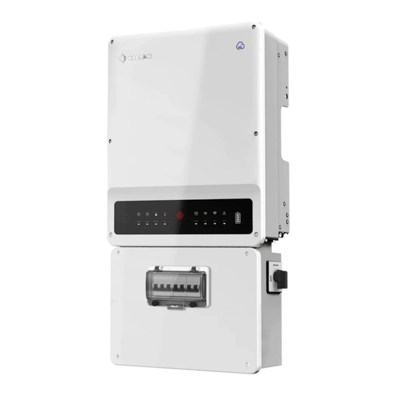
2.2 Model EHB series inverter models: • GW5000-EHB • GW6500-EHB • GW8600-EHB • GW0010-EHB 1213 2.3 Appearacne 7 8 9 No. Part Description PV input port To connect PV strings. Battery input port To connect the battery. BMS port To connect the BMS communication part of the battery. WiFi/Bluetooth port To install the WiFi/Bluetooth communication module. -
Page 9: Led Indicators Explanation
2.4 LED Indicators Explanation INDICATOR COLOR STATUS EXPLANATION ON = System is ready BLINK = System is starting up SYSTEM OFF = System is not operating ON = Back-up is ready / power available OFF = Back-up is off / on power available BACK-UP ON = Battery is charging BLINK 1 = Battery is discharging... -
Page 10: System Connection Diagrams
2.6 System Connection Diagrams • For Australia safety country, the neutral cable of On-Grid side and Back-Up side must be connected together, otherwise Back-Up function will not work. • When the inverter is working tied to the grid with its backup function enabled, it will automatically switch to the backup mode if the grid suddenly disconnected. - Page 11 The diagram is an example for application that Neutral separates with PE in distribution box. Such as: Australia, New Zealand, etc(Please follow local wiring regulations) Distribution box Back-up Loads Don’t connect this terminal to the Battery application where the neutral wire and PE wire are connected together.
-
Page 12: Installation Requirements
Installation Requirements 3.1 Environment Requirements • Any part of this system shouldn't block the switch and breaker from disconnecting the inverter from DC and AC power. • Inverter should be installed at eye level for convenient maintenance. • Inverter should be installed on a solid surface, where it is suitable for inverter's dimensions and weight. • Ambient temperature should be lower than 45°C. (High ambient temperature will cause power derating of inverter.) • It is recommanded that the installation of the inverter should be prevented from direct sunlight, snow, rain and other negative influences which may effect product function or lifetime. • Product label on inverter should be clearly visible after installation. Do not damage the lable. Keep away from sunlight Keep dry Keep it clear of snow Rain Accmulated snow 3.2 Installation Angle and Space Requirements Inverter should be installed vertically or lie Leave enough space around the inverter on a slope by a max of 15°. -
Page 13: Installing The Inverter
Generator Battery Battery Back-up Single battery bank cannot be connected to On-Grid or back-up side cannot be connected to multiple inverters. any AC generator. On-Grid Battery Back-up Battery without official compatible statement Back-up side cannot be connected to grid. cannot be connected to inverter Installing the Inverter 4.1 Packing List Straight... -
Page 14: Installing The Inverter
4.2 Installing the Inverter • Do not install the inverter when it is snowing or raining. If you have to, pay attention to the waterproof and moisture-proof of the inverter and distribution box. • Avoid drilling holes in walls which with cables inside or on the back. 1. Drill holes with the help of installation locating plate. -
Page 15: Electrical Connections
Electrical Connections • During wiring connection, the operator should always wear proper PPE. • The wiring installation must strictly observe correct specification. Otherwise, it may bring waterproof and electrical problems. • Direction of the CT cannot be connected in reverse, please follow House(K)→Grid (L) direction to do the connection. -
Page 16: Connecting The Pe Cable
5.2 Connecting the PE cable Ground cable shall be connected to ground plate on grid side. 5.3 Connecting PV Cables • The total short-circuit current of PV string must not exceed inverter’s max DC current. • The minmum isolation resistance to ground of the PV string must exceed 19.33kΩ... -
Page 17: Connecting Battery Dc Cables
5.4 Connecting Battery DC Cables • Make sure battery breaker is off and battery nominal voltage meet the Hybrid Inverter specification before connecting battery to inverter and make sure inverter is totally isolated from PV and AC power. • Please be careful against any electric shock or chemical hazard. • Please following Cments and steps bellow strictly. Use improper wire may cause bad contact and high impedance, which is dangerous to the system. • Use the right BAT plugs in the accessory box. • Use the tin-plated cables with a conductor cross section of 12 to 13 mm² because the maximum battery current is 50A. VACONN series Click 5.5 Connecting AC Cables AC circuit breakers shall be installed on the grid side and the load side. Select the AC breaker according to the actual load. AC breaker AC breaker Load breaker Load breaker... - Page 18 Requirements of AC cable connected to On-Grid and Back-Up side Make sure inverter is totally isolated from any DC or AC power before connecting AC cable. The choice of AC cable needs to meet both the outside diameter and conduct core section requirements. Please refer to the table for selecting the AC cable.
- Page 19 Grid the nominal output power of inverter is 110V Load 230V and there could be loads of 110V or Back-Up Load (230V) 220V. To Smart Meter 220V Load Declaration For Back-Up Function The below statement lays out the general policies governing the hybrid inverter. 1. For hybrid inverters, the standard PV installation typically consists of the connection of the inverter with both panels and batteries. In case of systems not connected to the batteries, the Back-Up function is strongly not advised to use. GoodWe shall not cover the standard warranty and be liable for any consequences arising from users not following this instruction. 2. Under normal circumstances, the Back-Up switching time is less than 10 ms (the minimal condition to be considered as the UPS level). However, some external factors may cause the system to fail on Back-Up mode. As such, we recommend the users to be aware of conditions and follow the instructions as below: 1) Do not connect loads if they are dependent on a stable energy supply for a reliable operation. 2) Do not connect the loads which may in total exceed the maximum Back-Up capacity. 3) Try to avoid those loads which may create very high start-up current surges such as Inverter Air-conditioner, high-power pump etc. 4) Due to the condition of battery itself, battery current might be limited by some factors including but not limited to the temperature, weather etc. Declaration For Back-Up Loads The hybrid inverters are able to supply over load output at its’ Back-Up. For details please refer to the technical parameters of the hybrid inverter. And the inverter has self-protection derating at...
-
Page 20: Connecting Communication Cables And Installing Ct
5.6 Connecting Communication Cables and Installing CT • The Smart Meter with CT in product box is compulsory for the hybrid inverter system installation, used to detect grid voltage and current direction and magnitude, further to instruct the operation condition of the hybrid inverter via RS485 communication. •... -
Page 21: Dred And Remote Shutdown Connection
BMS Meter 1 2 3 4 5 6 7 8 BMS Meter 5.7 DRED and Remote Shutdown Connection DRED is used for Australia and New Zealand installation (also used as remote shutdown function in European countries), in compliance with Australia and New Zealand safety requirements (or European countries). -
Page 22: Parameter Configuration
• [1]: Please connect to 5/6PIN of DRED port if Remote Shutdown is applied. • [2]: Connect BMS to this port if a battery with RS485 port is selected. • [3]: For LG RESH10-TypeR battery, connect the BMS cable to RS485_A2/ B2 port and connect the enable cable to LG_EN+ and LG_EN-. • [4]: Used to connect the data monitoring device. • The RS485 port shall be connected in the same way as the DRED port. • If the DRED and Remote Shutdown functions are not used, make sure that the Resistance is inserted into the DRED Terminal. DRED Cable connection Remote Shutdown Cable connection Single hole seal ring Cable Screw Screw cap RS485 communication board Reserved Terminal Resistance RS485 Terminal DRED Terminal Parameter Configuration... -
Page 23: Checking Before Turning On Ac Power
PV Input Connection: Confi rm the connection between inverter and battery, polarity (+/-) are not reversed. On-Grid & Back-Up Connection: Confi rm ON-GRID connection to power grid and Back-Up to loads, polarity (L/N are in sequence) not reversed. Smart Meter & CT Connection: Make sure Meter & CT are connected house loads and grid, and follow the Smart Meter direction sign on CT. 6.2 PV Master APP Operation 6.2.1 Basic Settings • PV Master app is an external monitoring/confi guration application for the hybrid inverters. • Please download PV Master app from GoodWe offi cial website (www.goodwe. com). • Connect to the WiFi/Bluetooth port to access the WiFi module/Bluetooth module, and realize the communication between the inverter and APP. PV Master APP • Bluetooth name: SOL-BLE******** • WiFi name: Solar-WiFi******** •... -
Page 24: Cei Auto-Test Function
Check the inverter and Check the meter direction. Select the battery type. battery status. WiFi Reset & Reload WiFi Reset & Reload function is only used when: WiFi lost connection to internet or cannot connect to PV Master APP successfully. Cannot find “Solar-WiFi signal” or have other WiFi configuration problem. Please do not use this button if WiFi monitoring works well. • WiFi Reset means restarting WiFi module, WiFi settings will be reprocessed and saved automatically. Short press REST button, WiFi LED on inverter will blink for a few seconds. • WiFi Reload means setting WiFi module back to default factory setting. Long press REST button (longer than 3s), WiFi LED on inverter will blink until doing WiFi configuration again. 6.2.2 CEI Auto-Test Function PV Auto-Test function of CEI is integrated in PV Master APP for Italy safety country requirement. For detailed instruction of this function please reger to PV Master Operation Instructions. 6.2.3 RSD Function The inverter supports the RSD function, which is optional and requires a quick shutdown device. Once the DC switch is turned off, the PV module can be quickly turned off. -
Page 25: Inverter Arc Detection (Optional)
6.2.4 Inverter Arc Detection (Optional) An electric arc is a gas discharge phenomenon. An instantaneous spark caused by an electric current passing through some insulating medium (such as air). The cause of the electric arc: • Connector is not connected well in photovoltaic system •... -
Page 26: Safety Parameter Settings
6.2.5 Safety Parameter Settings Set the QU curve, PU curve, and PF power curve in PV Master. Please contact the service center if you need to set them. (For Australia and New Zealand only) Steps to set the curves: "Settings→Advanced Setting→Custom safety parameters→Curve setting" PF Power Curve Mode cosФ 0.95 Power, (%P/P rated 0.95 LEGEND: cosФ PF Power Curve Mode Function Default value (Australia) Default value (New Zealand) Setting range B %P/Prated 30%~80% C Power factor 0.8-1 Power Recovery Slope Power Recovery Slope Function The default value (Australia & New Zealand) Setting range Rising slope 16.67%Pn/min 5-100%Pn/min Falling slope 16.67%Pn/min 5-100%Pn/min... - Page 27 PU curve Mode 100% 100% Example curve for a volt-watt response mode (Australia) Example curve for a volt-watt response mode (New Zealand) PU curve Mode (Discharge) Function Default value (Australia) Default value (New Zealand) Setting range V1 voltage ratio 207V 207V Not applicable P1 power ratio 100%*Pn 100%*Pn 0-100%*Pn V2 voltage ratio 220V 220V 216 to 230 P2 power ratio 100%*Pn 100%*Pn 0-100%*Pn V3 voltage ratio 250V...
- Page 28 QU curve Mode INVERTER VOLTAGE, V INVERTER VOLTAGE, V LEGEND: LEGEND: var characteristic curve var characteristic curve QU curve Mode Function Default value (Australia) Default value (New Zealand) Setting range V1 voltage ratio 207V 207V Not applicable Q1 reactive 30% leading 30% leading 0 to 60% leading power ratio V2 voltage ratio 220V 220V 216 to 230 Q2 reactive power ratio V3 voltage ratio 250V 244V 235 to 255 Q3 reactive power ratio V4 voltage ratio 265V...
-
Page 29: Wifi Configuration
2. If everything is right well, the WiFi LED on inverter will change from double blink to quartic blink then to solid status, which means WiFi is connected to GoodWe icloud successfully. 3. WiFi configuration could also be done on PV Master, details please check on PV Master APP. -
Page 30: Maintenance
Maintenance The inverter requires periodically maintenance, details as below: · Make sure inverter is totally isolated from all DC and AC power for at least 5 mins before maintenance. · Heat sink: Please use clean towel to clean up heat sink once a year. ·... -
Page 31: Troubleshootings
Troubleshootings 8.1 Error Message The error message below will be displayed on PV Master APP or reported by Email if the error really happens. Error Message Explanation Reason Solutions Public grid 1. Check (use multi-meter) if AC side has power is not Inverter does voltage . - Page 32 Error Message Explanation Reason Solutions Caused by a Try to restart the inverter,check if it still EEPROM R/W strong external occurs.If not,it is just an occasional situation. Failure magnetic field Otherwise, contact after-sales immediately. etc. Caused by a Internal Try to restart the inverter,check if it still strong external SPI Failure communication...
- Page 33 Error Message Explanation Reason Solutions 1. Use multi-meter to check if the resistance between earth & inverter frame is close Isolation failure to zero. If it's not, please ensure that the could be caused connection is well. by multiple 2. If the humidity is too high, isolation failure reasons like that may occur.
-
Page 34: Faq
8.2 FAQ Problems Solutions The inverter does not start Make sure the voltage of battery is higher than 100V, up with battery only. otherwise battery cannot start inverter up. Make sure the voltage of PV is highter than 100V (need The inverter not started up 200V to enter on-grid mode). - Page 35 Problems Solutions For Back-Up supply, the “Back-Up Supply” on PV Master App must be turned on. Under Off-Grid mode or grid power is disconnected, “Off-Grid Output Switch” function must be Why there is no output on turned on as well. Back-Up side? Note: As turn “Off-Grid Output Switch”...
- Page 36 Problems Solutions Why there is still power Export limit could theoretically to minimum 0W, but there will have a deviation of around 100W for the hybrid inverter exporting to grid after I set power limit as 0W? system. Can I use other brand Meter to take over Smart No, because the communication protocol is inset between Meter in the hybrid...
-
Page 37: Technical Parameters And Certificates
Technical Parameters and Certificates Technical Data GW5000-EHB GW6500-EHB GW8600-EHB GW0010-EHB Battery Input Data Battery Type Li-Ion )[2] Battery Voltage Range (V 80~495 )[1] Max. Charging Current (A) Max. Discharging Current (A) Charging Strategy for Li-Ion Self-adaption to BMS Battery PV String Input Data Max. - Page 38 Technical Data GW5000-EHB GW6500-EHB GW8600-EHB GW0010-EHB AC Output Data (Back-up) Nominal Output Voltage (V) 230 (±2%) (Vac) Nominal Output Frequency 50 (±0.2%) (Hz) Automatic Switch Time (ms) <10 Output THDv (@Linear <3% Load) Max. Continuous Output 5000 6500 8600 10000 Apparent Power(VA) Peak Output Apparent 6000, 60sec...
- Page 39 Technical Data GW5000-EHB GW6500-EHB GW8600-EHB GW0010-EHB Battery Input Reverse Integrated Polarity Protection General Data Operating Temperature -35~60 Range(℃) Relative Humidity 0~95% Operating Altitude (m) ≤4000 Cooling Intelligent Fan Noise (dB) <50 User Interface LED & APP(WiFi&Bluetooth) DC&AC Power Connect Port MC4 &...
-
Page 40: Appendix
Appendix Other Tests For Australian requirements, in the THDi test, Zref should be added between the inverter and mains. RA, XA for the line conductor RN, XN for the neutral conductor Zref: RA = 0, 24, XA = j0,15 at 50Hz Category IV RN = 0, 16, XN = j0,10 at 50Hz Protection category definition... - Page 41 Overvoltage category definition Applies to equipment connected to a circuit where measures have been Category I taken to reduce transient overvoltage to a low level. Applies to equipment not permanently connected to the installation. Category II Examples are appliances, portables tools and other plug-connected equipment.
- Page 42 PV Master APP SEMS Portal APP SEMS Portal website LinkedIn Company's www.semsportal.com offical website JIANGSU GOODWE POWER SUPPLY TECHNOLOGY CO.,LTD No. 90 Zijin Rd., New District, Suzhou, 215011, China www.goodwe.com service@goodwe.com 340-00462-00...
Need help?
Do you have a question about the EHB Series and is the answer not in the manual?
Questions and answers