Table of Contents
Advertisement
Quick Links
Advertisement
Table of Contents

Related Manuals for Goodwe EHB Series


Summary of Contents for Goodwe EHB Series
- Page 1 EHB Series Quick Installation Guide Ver.1.0 2020-12-30...
-
Page 2: Safety And Warning
Safety and Warning General safety cautions • The documentation may be updated from time to time due to product upgrades or other reasons. Unless otherwise specified, information in the documentation do not replace safety cautions in the labels. All descriptions in the documentation are used for guidance only. • Please read the user manual carefully to acquire knowledge about product features and safety precautions before installing the equipment. GoodWe will not be liable for any equipment damages or personnel injuries caused by failure to install, operate or configure the inverter in accordance with this document or corresponding user manual. • Please follow local laws and regulations, and safety cautions in this manual during the installation, operation, and maintenance. Improper operation or misuse may result in personal injuries or property losses. • All installation, operation, and maintenance must be carried out by trained professionals who meet the following requirements: • read through this manual • be familiar with various safety precautions • operate properly • acquaint with local laws, regulations, and standards. • To ensure safety, please use insulated tools and wear personal protective equipment when operating the equipment. • Always comply with electrostatic protection rules. To protect the inverter from being damaged, please wear anti-static gloves, wrist strap and clothes when touching printed circuit board or other electrostatic sensitive components during operation. Operation Safety Precautions • Power off the equipment before any cable connection or electrical operation. - Page 3 • The equipment can get hot during operation. Touching the hot surface can result in burn injuries. • Make sure battery breaker is off and battery nominal voltage meet the Hybrid Inverter specification before connecting battery to inverter and make sure inverter is totally isolated from PV and AC power. • If the equipment is not to be installed immediately, put it inside the original package with the desiccant. If the equipment is unpacked but not put into use immediately, seal all unused terminal ports to prevent dust and water vapor corrosion. • Please be careful against any electric shock or chemical hazard. • Please following Cments and steps bellow strictly. Use improper wire may cause bad contact and high impedance, which is dangerous to the system. Warranty Declaration • The equipment damage caused by following reasons are not covered by warranty: • Exceed the guarantee period. • Improper installation, alteration, transportation or operation. • The installation or operation environment is beyond the requirements of this manual or local laws and regulations. • Force majeure (lightening, earthquake, fire disaster, storm or volcanic eruption etc.) • Unauthorized replacement, dismantle, maintenance or modification of software code. • Failure to comply with local laws and regulations, and safety precautions in this manual. For more warranty conditions, please visit www.goodwe.com.
-
Page 4: Product Introduction
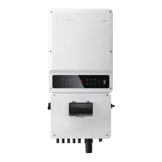
Product Introduction 1213 7 8 9 1. PV input port 2. Battery input port 3. BMS port 4. WiFi/Bluetooth port 5. METER port 6. ON-GRID port 7. DRED communication port 8. RS485 port 9. BACK-UP port 10. WiFi Reset Button 11. Indicator 12. Bypass switch 13. DC switch 14. Breaker Installing the Inverter Packing List Straight Smart Meter*1 Wall-Mounted Wall-Mounted 6-Pin Terminal*2 Screwdriver*1 &CT*1 Bracket*1 Bracket*1 Inverter*1 Positive PV Negative PV Positive BAT Negative BAT Plug... - Page 5 Dimension 192 mm 415 mm 182 mm 175 mm 106 mm 140 mm Angle Space 500mm 300mm...
- Page 6 Installing the Inverter 1. Drill holes with the help of installation locating plate. 2. Install the wall-mounted bracket. 3. Install the inverter. 4. Secure the inverter with a lock. 5. Ensure that the switch is on "OFF" position and locked during installation and maintenance. (Applicable in Australia and New Zealand) Level Φ8mm...
-
Page 7: Electrical Connections
Electrical Connections Overview of Cable Connections Grid Power Meter AC Breaker ..To Smart Meter Cable Please connect the CT PV Strings from House (K) to Grid (L). AC Breaker ON-Grid Load The AC breaker specification depends on actual loads. Back-Up Load Battery Cable Specifications Model PV Cable BAT Cable AC Cable PE Cable GW5000-EHB 3-4mm²... - Page 8 Connecting PV Cables 1. Use the right plugs in the accessory box. Prepare cables and plugs. 2. Connect cables to connectors. 3. Screw the cap on and plug onto inverter side. Click Connecting Battery DC Cables 1. Use the right plugs in the accessory box. Prepare cables and plugs. 2.
- Page 9 Connecting AC Cables AC circuit breakers shall be installed on the grid side and the load side. Select the AC breaker according to the actual load. AC breaker AC breaker Load breaker Load breaker Prepare the terminals and AC cables. Put AC cable through terminal cover and screw the three cables tightly on the connectors. Lock terminal cover and screw up the terminal cap. Connect the assambled AC terminals onto inverter. 10-15mm 12-14mm Φ: 13-22mm Make sure terminal...
- Page 10 BMS Meter 1 2 3 4 5 6 7 8 BMS Meter DRED and Remote Shutdown Connection DRED port definition Reserved port definition RS485 port definition DRM1/5 CANL2 RS485_B2 DRM2/6 CANH2 RS485_A2 DRM3/7 GND-S LG_EN- DRM4/8 12V-S LG_EN+ REFGEN/Remote Shutdown NODE- RS485_B1 COM/DRM0/Remote...
- Page 11 • [1]: Please connect to 5/6PIN of DRED port if Remote Shutdown is applied. • [2]: Connect BMS to this port if a battery with RS485 port is selected. • [3]: For LG RESH10-TypeR battery, connect the BMS cable to RS485_A2/ B2 port and connect the enable cable to LG_EN+ and LG_EN-. • [4]: Used to connect the data monitoring device. • The RS485 port shall be connected in the same way as the DRED port. • If the DRED and Remote Shutdown functions are not used, make sure that the Resistance is inserted into the DRED Terminal. DRED Cable connection Remote Shutdown Cable connection Single hole seal ring Cable Screw Screw cap RS485 communication board Reserved Terminal Resistance RS485 Terminal DRED Terminal...
-
Page 12: Parameter Configuration
2. PV Input Connection: Confi rm the connection between inverter and battery, polarity (+/-) are not reversed. 3. On-Grid & Back-Up Connection: Confi rm ON-GRID connection to power grid and Back-Up to loads, polarity (L/N are in sequence) not reversed. 4. Smart Meter & CT Connection: Make sure Meter & CT are connected house loads and grid, and follow the Smart Meter direction sign on CT. PV Master APP Operation • PV Master app is an external monitoring/confi guration application for the hybrid inverters. • Please download PV Master app from GoodWe offi cial website (www.goodwe. com). • Connect to the WiFi/Bluetooth port to access the WiFi module/Bluetooth module, and realize the communication between the inverter and APP. PV Master APP • Bluetooth name: SOL-BLE******** • WiFi name: Solar-WiFi******** •... - Page 13 Check the inverter and Check the meter direction. Select the battery type. battery status. WiFi Reset & Reload WiFi Reset & Reload function is only used when: WiFi lost connection to internet or cannot connect to PV Master APP successfully. Cannot find “Solar-WiFi signal” or have other WiFi configuration problem. Please do not use this button if WiFi monitoring works well. • WiFi Reset means restarting WiFi module, WiFi settings will be reprocessed and saved automatically. Short press REST button, WiFi LED on inverter will blink for a few seconds. • WiFi Reload means setting WiFi module back to default factory setting. Long press REST button (longer than 3s), WiFi LED on inverter will blink until doing WiFi configuration again.
- Page 14 2. If everything is right well, the WiFi LED on inverter will change from double blink to quartic blink then to solid status, which means WiFi is connected to GoodWe icloud successfully. 3. WiFi configuration could also be done on PV Master, details please check on PV Master APP.
- Page 15 Smart Meter LED Indicators Explanation Smart Meter LED Indications Blinking POWER POWER Not working Working ENERGY ENERGY Importing Exporting Blink one time when it transfer data to inverter. Inverter LED Indicators Explanation INDICATOR COLOR STATUS EXPLANATION ON = System is ready BLINK = System is starting up SYSTEM OFF = System is not operating...
- Page 16 PV Master APP SEMS Portal APP SEMS Portal website LinkedIn Company's www.semsportal.com offical website JIANGSU GOODWE POWER SUPPLY TECHNOLOGY CO.,LTD No. 90 Zijin Rd., New District, Suzhou, 215011, China www.goodwe.com 340-00463-00 service@goodwe.com...
Need help?
Do you have a question about the EHB Series and is the answer not in the manual?
Questions and answers