Goodwe EH Series User Manual
Hybrid inverter
Hide thumbs
Also See for EH Series:
- Quick installation manual (110 pages) ,
- User manual (41 pages) ,
- Manual (18 pages)
Table of Contents
Advertisement
Advertisement
Table of Contents

Related Manuals for Goodwe EH Series


Summary of Contents for Goodwe EH Series
- Page 1 User Manual Hybrid Inverter EH Series/EH Plus Series 3.6-6kW V1.4-2022-8-30...
- Page 2 Copyright © GoodWe Technologies Co.,Ltd. 2022. All rights reserved. No part of this manual can be reproduced or transmitted to the public platform in any form or by any means without the prior written authorization of GoodWe Technologies Co.,Ltd. Trademarks and other GOODWE trademarks are trademarks of GoodWe Technologies Co.,Ltd.
-
Page 3: Table Of Contents
CONTENT User Manual V1.4-2022-08-30 CONTENT 1 About This Manual ���������������������������������������������������������������������������� 1 1.1 Applicable Model ........................1 1.2 Target Audience ........................1 1.3 Symbol Definition ........................2 1.4 Updates ............................2 2 Safety Precaution ����������������������������������������������������������������������������� 3 2.1 General Safety ..........................3 2.2 PV String Safety ........................3 2.3 Inverter Safety ..........................4 2.4 Battery Safety ...........................5 2.5 Personal Requirements ......................5... - Page 4 User Manual V1.4-2022-08-30 CONTENT 6.4 Connecting the DC Input Cable (PV) ..................27 6.5 Connecting the battery cable ....................30 6.6 Connecting the AC Cable ....................... 33 6.6.1 Connecting the AC Cable (ON-GRID) ..................... 34 6.6.2 Connecting the AC Cable (BACK-UP) ..................... 34 6.7 Communication Connection ....................
-
Page 5: About This Manual
All the installers and users have to be familiar with the product features, functions, and safety precautions. This manual is subject to update without notice. For more product details and latest documents, visit https://en.goodwe.com. 1.1 Applicable Model... -
Page 6: Symbol Definition
01 About This Manual User Manual V1.4-2022-08-30 1.3 Symbol Definition Different levels of warning messages in this manual are defined as follows: DANGER Indicates a high-level hazard that, if not avoided, will result in death or serious injury. WARNING Indicates a medium-level hazard that, if not avoided, could result in death or serious injury. CAUTION Indicates a low-level hazard that, if not avoided, could result in minor or moderate injury. -
Page 7: Safety Precaution
• Strictly follow the installation, operation, and configuration instructions in this manual. The manufacturer shall not be liable for equipment damage or personal injury if you do not follow the instructions. For more warranty details, please visit https://en.goodwe.com/ warranty. 2.2 PV String Safety DANGER Connect the DC cables of the inverter to the delivered DC terminals. -
Page 8: Inverter Safety
02 Safety Precaution User Manual V1.4-2022-08-30 2.3 Inverter Safety WARNING • The voltage and frequency at the connection point meet the inverter grid connection requirements. • Additional protective devices like circuit breakers or fuses are recommended on the AC side. Specification of the protective device should be at least 1.25 times the rated AC output rated current. -
Page 9: Battery Safety
2.6 EU Declaration of Conformity GoodWe Technologies Co., Ltd. hereby declares that the inverter with wireless communication modules sold in the European market meets the requirements of the following directives: • Radio Equipment Directive 2014/53/EU (RED) •... -
Page 10: Product Introduction
• GW3600N-EH • GW5000N-EH • GW6000N-EH Model description GW3000N-EH Referring to Explanation Brand Code GW: GoodWe Rated Power 3000: the rated power is 3000W. Product Feature N: higher PV input current Series Code EH: single-phase hybrid inverter Supported Grid Types... -
Page 11: Application Scenarios
User Manual V1.4-2022-08-30 03 Product Introduction 3.2 Application Scenarios WARNING • The PV system is not suitable to connect equipment that relies on a stable power supply, such as medical equipment to sustain life. Ensure that no personal injury is occurred when the system is disconnected. - Page 12 Parts Description PV String The PV string consists of PV modules. Inverter Support EH series and EH Plus series inverters. Battery Select the battery model according to the inverter model and the approved battery list. Battery Recommended specifications: nominal current≥40A, nominal breaker voltage≥600V.
-
Page 13: Working Mode
User Manual V1.4-2022-08-30 03 Product Introduction 3.3 Working Mode 3.3.1 System Working Mode Economic mode NOTICE • Select Economic mode only when it meets the local laws and regulations, e.g., whether the grid is allowed to charge the battery. If not, do not use this mode. •... - Page 14 03 Product Introduction User Manual V1.4-2022-08-30 Self consumption mode NOTICE • For solar power, consider self consumption mode in priority: the excess power charges the battery in day time; the battery supplies power to the load when there is no solar power generated at night.
- Page 15 User Manual V1.4-2022-08-30 03 Product Introduction Back-up mode NOTICE • The back-up mode is mainly applied to the scenario where the grid is unstable and there is an important load. When the grid is disconnected, the inverter turns to off-grid mode to supply power to the load;...
-
Page 16: Inverter Operation Mode
03 Product Introduction User Manual V1.4-2022-08-30 3.3.3 Inverter Operation Mode Waiting mode Off-grid mode Self-check mode Grid-Tied mode Fault mode Parts Description Waiting Waiting stage after the inverter is powered on. mode • When the conditions are met, it enters the self-check mode. •... -
Page 17: Features
User Manual V1.4-2022-08-30 03 Product Introduction 3.4 Features Power Derating For a safe operation, the inverter will automatically reduce the output power when the operating environment is not ideal. The following are the factors that may occur power derating. Please try to avoid them when the inverter is working. -
Page 18: Appearance
03 Product Introduction User Manual V1.4-2022-08-30 3.5 Appearance 3.5.1 Parts PV input terminal Battery input terminal DC switch (PV1/PV2) (BAT +/-) Communication module Meter communication BMS communication port port port (WiFi or LAN) DRED communication Back-Up port On-Grid port port RS485 communication Wi-Fi reset 12. -
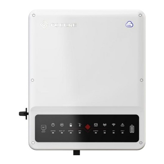
Page 19: Indicators
User Manual V1.4-2022-08-30 03 Product Introduction 3.5.3 Indicators Indicators Status Description ON = The system is ready. SYSTEM BLINK = The system is starting. OFF =The system is not working. ON = Back-up is ready / power available. BACK-UP OFF = Back-up is off / power not available. ON = The battery is charging. -
Page 20: Nameplate
Safety symbols and certification marks Contact information and serial number Good We Tec hno lo gi es Co., Ltd. E-ma il :s ervi ce @goodwe .c om No.90 Ziji n Rd., New Dis tric t, S uz hou , 2150 11, Chin a... -
Page 21: Check And Storage
User Manual V1.4-2022-08-30 04 Check and Storage 4 Check and Storage 4.1 Check Before Receiving Check the following items before receiving the product. 1. Check the outer packing box for damage, such as holes, cracks, deformation, and other signs of equipment damage. Do not unpack the contents from the box and contact the supplier as soon as possible if any damage is found. -
Page 22: Storage
04 Check and Storage User Manual V1.4-2022-08-30 4.3 Storage If the equipment is not to be installed or used immediately, please ensure that the storage environment meets the following requirements: 1. Do not unpack the outer package or throw the desiccant away. 2. -
Page 23: Installation
User Manual V1.4-2022-08-30 05 Installation 5 Installation 5.1 Installation Requirements Installation Environment Requirements 1. Do not install the equipment in a place near flammable, explosive, or corrosive materials. 2. Do not install the equipment in a place that is easy to touch, especially within children’s reach. High temperature exists when the equipment is working. - Page 24 05 Installation User Manual V1.4-2022-08-30 ALT: 3000m (*2000m for EH IP65 series in Australia) 0%~95%RH Mounting Support Requirements • The mounting support shall be nonflammable and fireproof. • Install the equipment on a surface that is solid enough to bear the inverter weight. •...
- Page 25 User Manual V1.4-2022-08-30 05 Installation Installation Tool Requirements The following tools are recommended when installing the equipment. Use other auxiliary tools on site if necessary. RJ45 Goggles Safety shoes Safety gloves Dust mask crimping tool Diagonal pliers Wire stripper Hammer drill Heat gun Vacuum cleaner M3/M5...
-
Page 26: Inverter Installation
05 Installation User Manual V1.4-2022-08-30 5.2 Inverter Installation 5.2.1 Moving the Inverter CAUTION • Operations such as transportation, shipment, installation and so on shall in compliance with the laws and regulations of the country or region where the inverter is located. •... - Page 27 User Manual V1.4-2022-08-30 05 Installation Only for Australia.
-
Page 28: Electrical Connection
05 Installation User Manual V1.4-2022-08-30 6 Electrical Connection 6.1 System Wiring Diagram NOTICE • N and PE wiring via ON-GRID and BACK-UP ports of the inverter are different based on the regulation requirements of different regions. Refer to the specific requirements of local regulations. - Page 29 User Manual V1.4-2022-08-30 05 Installation N and PE cables are separately wired in the Main Panel. NOTICE The following diagram is applicable to areas except Australia, New Zealand, South Africa. BACK-UP BACK-UP Loads Battery Meter Smart meter ON-GRID PV string Utility grid E-BAR E-BAR...
-
Page 30: Safety Precautions
06 Electrical Connection User Manual V1.4-2022-08-30 6.2 Safety Precautions DANGER • Perform electrical connections in compliance with local laws and regulations. Including operations, cables, and component specifications. • Disconnect the DC switch and the AC output switch of the inverter to power off the inverter before any electrical connections. -
Page 31: Connecting The Dc Input Cable (Pv)
User Manual V1.4-2022-08-30 06 Electrical Connection L=L1+(1-2)mm L1 Copper, ≥4mm 6.4 Connecting the DC Input Cable (PV) DANGER • Do not connect one PV string to more than one inverter at the same time. Otherwise, it may cause damage to the inverter. •... - Page 32 06 Electrical Connection User Manual V1.4-2022-08-30 Vaconn 7-8mm Φ: 5.5-8mm 7-8mm 2.5mm ≤S≤4mm Click Click ≤580V...
- Page 33 User Manual V1.4-2022-08-30 06 Electrical Connection 7-8mm Φ: 4-5mm 7-8mm ≤S≤6mm Click Click ≤580V...
-
Page 34: Connecting The Battery Cable
06 Electrical Connection User Manual V1.4-2022-08-30 6.5 Connecting the Battery Cable NOTICE • For Battery-Ready inverters, please contact the manufacturer or dealer to activate the battery related functions first if you need them. Do not connect any battery to the inverter if the battery related functions are not activated. - Page 35 User Manual V1.4-2022-08-30 06 Electrical Connection Click Phoenix 15mm Φ: 5.5-8mm 15mm Φ: 5.5-8mm ≤S≤6mm Click...
- Page 36 06 Electrical Connection User Manual V1.4-2022-08-30 Vaconn 7-8mm Φ: 4-5mm 7-8mm ≤S≤6mm Click Click...
-
Page 37: Connecting The Ac Cable
User Manual V1.4-2022-08-30 06 Electrical Connection 6.6 Connecting the AC Cable NOTICE • Install one AC circuit breaker for each inverter. Multiple inverters cannot share one AC circuit breaker. Do not connect loads between the inverter and the AC switch directly connected to the inverter. -
Page 38: Connecting The Ac Cable (On-Grid)
06 Electrical Connection User Manual V1.4-2022-08-30 6.6.1 Connecting the AC Cable (ON-GRID) 12-14mm Φ: 13-22mm 10-15mm Copper, 6≤S≤10mm 6.6.2 Connecting the AC Cable (BACK-UP) NOTICE • Ensure that the BACK-UP PE cable is connected properly and securely. Otherwise, the BACK- UP function may not work when the grid fails. - Page 39 User Manual V1.4-2022-08-30 06 Electrical Connection WARNING • The absence of an AC breaker on the BACK-Up side may lead to inverter damage once an electrical short-circuit happens. And the BACK-UP function cannot be turned off when the inverter is on grid. •...
-
Page 40: Communication Connection
06 Electrical Connection User Manual V1.4-2022-08-30 6.7 Communication Connection 6.7.1 Connecting the Communication Cable NOTICE • Make sure that the communication device is connected to the right COM port. Route the communication cable far away from any interference source or power cable to prevent the signal from being influenced. -
Page 41: Connecting Bms Or Meter Communication Cable (Optional)
User Manual V1.4-2022-08-30 06 Electrical Connection 6.7.2 Connecting BMS or Meter Communication Cable (Optional) NOTICE • The smart meter and CT have been preset parameters before delivered with the inverter. Do not modify the relevant parameters. • The BMS communication cable and communication cable between the inverter and the smart meter is included. - Page 42 06 Electrical Connection User Manual V1.4-2022-08-30 To smart meter To battery Battery Smart meter RS485 NOTICE Power limit can be realized when the inverter is installed with a smart meter. The specific networkings are as follows. Single phase scenario When single phase loads are connected, the power limit can be realized by connecting EH or EH Plus series inverters with GM1000.
-
Page 43: Installing The Communication Module (Optional)
NOTICE Refer to the delivered communication module user manual to get more introduction to the module. For more detailed information, visit www.goodwe.com. WiFi Reset or Reload Short press the reset button. The WiFi indicator will blink until the WiFi module is reset. -
Page 44: Equipment Commissioning
07 Equipment Commissioning User Manual V1.4-2022-08-30 7 Equipment Commissioning 7.1 Check Before Power ON Check Item The product is firmly installed at a clean place that is well-ventilated and easy-to operate. The PE, DC input, AC output, and communication cables are connected correctly and securely. -
Page 45: System Commissioning
User Manual V1.4-2022-08-30 08 System Commissioning 8 System Commissioning 8.1 Indicators and Buttons Indicators Status Description ON = The system is ready. SYSTEM BLINK = The system is starting. OFF =The system is not working. ON = Back-up is ready / power available. BACK-UP OFF = Back-up is off / power not available. -
Page 46: Setting Inverter Parameters Via Pv Master App
2. Set grid parameters, communication parameters, safety countries, power limitation, etc. 3. Equipment maintenance. 4. Upgrade software version. For more details, refer to PV Master User Manual. Scan the QR code or visit GoodWe official site to get the user manual. https://en.goodwe.com/Ftp/EN/Downloads/User%20Manual/GW_PV%20Master_User%20 Manual-EN.pdf... -
Page 47: Maintenance
User Manual V1.4-2022-08-30 09 Maintenance 9 Maintenance 9.1 Power OFF the Inverter DANGER • Power off the inverter before operations and maintenance. Otherwise, the inverter may be damaged or electric shocks may occur. • Delayed discharge. Wait until the components are discharged after power off. Step 1: Turn off the AC breaker on the ON-GRID side of the inverter. -
Page 48: Troubleshooting
09 Maintenance User Manual V1.4-2022-08-30 9.4 Troubleshooting Perform troubleshooting according to the following methods. Contact the after-sales service if these methods do not work. Collect the information below before contacting the after-sales service, so that the problems can be solved quickly. 1. - Page 49 User Manual V1.4-2022-08-30 09 Maintenance No. Fault Cause Solutions 1. If the problem occurs occasionally, the utility grid may be abnormal temporarily. The inverter will recover automatically after detecting that the utility grid is normal. 2. If the problem occurs frequently, check whether the grid voltage is within the The grid voltage is Grid Rapid...
- Page 50 09 Maintenance User Manual V1.4-2022-08-30 No. Fault Cause Solutions 1. If the problem occurs occasionally, the utility grid may be abnormal temporarily. The inverter will recover automatically after detecting that the utility grid is normal. Utility grid 2. If the problem occurs frequently, check exception.
- Page 51 User Manual V1.4-2022-08-30 09 Maintenance No. Fault Cause Solutions 1. If the problem occurs occasionally, the utility grid may be abnormal temporarily. Utility grid The inverter will recover automatically after exception. The detecting that the utility grid is normal. actual grid 2.
- Page 52 09 Maintenance User Manual V1.4-2022-08-30 No. Fault Cause Solutions 1. The PV string is short-circuited 1. Check whether the resistance of the PV string to PE. to PE exceeds 50kΩ. If no, check the short 2. The PV system circuit point. Low Insulation is in a moist 2.
- Page 53 User Manual V1.4-2022-08-30 09 Maintenance No. Fault Cause Solutions Disconnect the AC output switch and DC input The sampling of GFCI HCT Check switch, then connect them 5 minutes later. the GFCI HCT is abnormal Contact the dealer or the after-sales service if abnormal.
- Page 54 09 Maintenance User Manual V1.4-2022-08-30 No. Fault Cause Solutions The PV array configuration is Check the serial connection of the PV array. PV Input not correct. Too Make sure that the open circuit voltage of the Overvoltage many PV panels are PV string is not higher than the maximum connected in series operating voltage of the inverter.
-
Page 55: Routine Maintenance
User Manual V1.4-2022-08-30 09 Maintenance 9.5 Routine Maintenance WARNING • Make sure that the inverter is powered off. • Wear proper PPE before any operations. Maintaining Item Maintaining Method Maintaining Period Check the heat sink, air intake, and air System Clean Once 6-12 months outlet for foreign matter or dust. -
Page 56: Technical Parameters
10 Technical Parameters User Manual V1.4-2022-08-30 10 Technical Parameters 10.1 General Technical Parameters Technical Data GW3600-EH GW5000-EH GW6000-EH Battery Input Data Battery Type Li-Ion Nominal Battery Voltage (V) Battery Voltage Range (V) 85~460 Max. Continuous Charging Current Max. Continuous Discharging Current (A) Max. - Page 57 User Manual V1.4-2022-08-30 10 Technical Parameters Max. Apparent Power Output to 3600/3960 5000/5500 6000/6600 Utility Grid (VA) Nominal Apparent Power from 7,200 10,000 12,000 Utility Grid(VA) 7200(Charging 10000(Charging 12,000 (Charging Max. Apparent Power from Utility 3.6kw, Backup 5kw, Backup 6kW, Backup Grid (VA) Output 3.6kw) Output 5kw)
- Page 58 10 Technical Parameters User Manual V1.4-2022-08-30 Maximum Output Overcurrent 21.7 26.1 Protection (A) Nominal Output Voltage (V) 230 (±2%) Nominal Output Frequency (Hz) 50/60 (±0.2%) Output THDv (@Linear Load) <3% Efficiency Max. Efficiency 97.6% European Efficiency 97.0% Max. Battery to AC Efficiency 96.6% MPPT Efficiency 99.9%...
- Page 59 User Manual V1.4-2022-08-30 10 Technical Parameters Self-consumption at Night (W) <10 Ingress Protection Rating IP65 DC Connector MC4 (4~6 mm AC Connector Quick Plug Environmental Category 4K4H Pollution Degree Overvoltage Category DC II / AC III Protective Class Storage Temperature (℃) -40~+85 Battery: C PV: C...
- Page 60 10 Technical Parameters User Manual V1.4-2022-08-30 Technical Data GW3600N-EH GW5000N-EH GW6000N-EH Battery Input Data Battery Type Li-Ion Nominal Battery Voltage (V) Battery Voltage Range (V) 85~460 Max. Continuous Charging Current Max. Continuous Discharging Current (A) Max. Charge Power (W) 6,000 Max.
- Page 61 User Manual V1.4-2022-08-30 10 Technical Parameters 10,000 7200 (Charging 12,000 (Charging Max. Apparent Power from Utility (Charging 5kW, 3.6kW, Backup 6kW, Backup Grid (VA) Backup Output Output 3.6kW) Output 6kW) 5kW) Nominal Output Voltage (V) 230/220 Output Voltage Range (V) 0~300 Nominal AC Grid Frequency (Hz) 50/60...
- Page 62 10 Technical Parameters User Manual V1.4-2022-08-30 Maximum Output Overcurrent 18.8 26.1 26.1 Protection (A) Nominal Output Voltage (V) 230 (±2%) Nominal Output Frequency (Hz) 50/60 (±0.2%) Output THDv (@Linear Load) <3% Efficiency Max. Efficiency 97.6% European Efficiency 97.0% Max. Battery to AC Efficiency 96.6% MPPT Efficiency 99.9%...
- Page 63 User Manual V1.4-2022-08-30 10 Technical Parameters Topology Non-isolated Self-consumption at Night (W) <10 Ingress Protection Rating IP65 DC Connector MC4 (4~6 mm AC Connector Quick Plug Environmental Category 4K4H Pollution Degree Overvoltage Category DC II / AC III Protective Class Storage Temperature (℃) -40~+85 Battery: C...
-
Page 64: Technical Parameters - Belgium
10 Technical Parameters User Manual V1.4-2022-08-30 10.2 Technical Parameters - Belgium Technical Data GW3600N-EH GW5000N-EH GW6000N-EH Battery Input Data Battery Type Li-Ion Nominal Battery Voltage (V) Battery Voltage Range (V) 85~460 Max. Continuous Charging Current (A) Max. Continuous Discharging Current Max. - Page 65 User Manual V1.4-2022-08-30 10 Technical Parameters 10,000 7,200 (Charging 12,000 (Charging Max. Apparent Power from Utility (Charging 5kW, 3.6kW, Backup 6kW, Backup Grid (VA) Backup Output Output 3.6kW) Output 6kW) 5kW) Nominal Output Voltage (V) Output Voltage Range (V) 0~300 Nominal AC Grid Frequency (Hz) 50/60 AC Grid Frequency Range (Hz)
- Page 66 10 Technical Parameters User Manual V1.4-2022-08-30 Maximum Output Overcurrent 18.8 26.1 31.3 Protection (A) Nominal Output Voltage (V) 230 (±2%) Nominal Output Frequency (Hz) 50/60 (±0.2%) Output THDv (@Linear Load) <3% Efficiency Max. Efficiency 97.6% European Efficiency 97.0% Max. Battery to AC Efficiency 96.6% MPPT Efficiency 99.9%...
- Page 67 User Manual V1.4-2022-08-30 10 Technical Parameters Self-consumption at Night (W) <10 Ingress Protection Rating IP65 DC Connector MC4 (4~6 mm AC Connector Quick Plug Environmental Category 4K4H Pollution Degree Overvoltage Category DC II / AC III Protective Class Storage Temperature (℃) -40~+85 Battery: C PV: C...
- Page 68 Official Website GoodWe Technologies Co.,Ltd. No. 90 Zijin Rd., New District, Suzhou, 215011, China T: 400-998-1212 www.goodwe.com service@goodwe.com Contact Information...
Need help?
Do you have a question about the EH Series and is the answer not in the manual?
Questions and answers