
Related Manuals for Hydac OXiStop OXS LID Series


Summary of Contents for Hydac OXiStop OXS LID Series
- Page 1 OXiStop OXS-LID Installation and Maintenance Instructions English (translation of original instructions) Document no.: 3992764e...
-
Page 2: Imprint
Court of Registration: Saarbrücken, HRB 17216 Executive director: Mathias Dieter, Dipl.Kfm. Wolfgang Haering Documentation Representative Mr. Günter Harge c/o HYDAC International GmbH, Industriegebiet, 66280 Sulzbach / Saar Phone: +49 (0) 6897 509 1511 Fax: +49 (0) 6897 509 1394 E-mail: guenter.harge@hydac.com ©... -
Page 3: Table Of Contents
Content Content Imprint ......................2 Documentation Representative ..............2 Content ......................3 Preface ......................6 Technical Support ..................6 Modifications to the Product ................ 6 Warranty ...................... 6 Using the documentation ................7 General Safety Information ................8 Hazard symbols ................... 8 Signal words and their meaning in the general safety information .... - Page 4 Content Monitoring the unit's sensors/displays ............. 38 Monitoring unit function................40 Fluid level indicator, visual – Min/Max marking .......... 43 Connecting electronic fluid level/temperature sensor HNS ......44 Connecting AquaSensor AS (optional) ............45 Connecting ContaminationSensor CS1000 (optional) ....... 46 Starting up the unit ..................
- Page 5 Content Technical Data................... 101 Model code ....................103 Index ......................104 OXiStop OXS-LID Page 5 / 112 MoWa OXS-LID 3992764e en-us 2018-08-10.docx 2018-08-10...
-
Page 6: Preface
After modification or repair work that affects the safety of the product has been carried out on components, the product may not be returned to operation until it has been checked and released by a HYDAC technician. Please notify us immediately of any modifications made to the product whether by you or a third party. -
Page 7: Using The Documentation
Preface Using the documentation Note that the method described for locating specific information does not release you from your responsibility of carefully reading these instructions prior to starting the unit up for the first time and at regular intervals in the future. What do I want to know? I determine which topic I am looking for. -
Page 8: General Safety Information
General Safety Information General Safety Information The unit was built according to the statutory provisions valid at the time of delivery and satisfies current safety requirements. Any residual hazards are indicated by safety information and instructions and are described in the operating instructions. Observe all safety and warning instructions attached to the unit. -
Page 9: Signal Words And Their Meaning In The General Safety Information
General Safety Information Risk of burns due to hot surfaces Substances that are health hazards or irritants Danger of explosion in explosive atmospheres Signal words and their meaning in the general safety information DANGER DANGER – The signal word indicates a hazardous situation with a high level of risk, which, if not avoided, will result lethal or serious injury. -
Page 10: Structure Of The General Safety Information
General Safety Information Structure of the general safety information All warning instructions in this manual are highlighted with pictograms and signal words. The pictogram and the signal word indicate the severity of the danger. Warning instructions listed before an activity are laid out as follows: SIGNAL WORD Type and source of danger HAZARD SYMBOL... -
Page 11: Proper/Designated Use
General Safety Information Proper/designated use Use the unit only for the application described in the following. The OXS is a tank system with an integrated diaphragm and a hydraulically driven degassing and dewatering unit. The integrated diaphragm prevents direct contact with the ambient air. This effectively "vacuum-packs"... -
Page 12: Improper Use Or Use Deviating From Intended Use
Any use extending beyond this or deviating therefrom shall not be considered intended use. HYDAC Filter Systems GmbH will assume no liability for any damage resulting from such use. The user alone, shall assume any and all associated risk. -
Page 13: Qualifications Of Personnel / Target Group
General Safety Information Qualifications of personnel / target group Persons who work on the power unit must be aware of the associated hazards when using the power unit. Operating and specialist personnel must have read and understood the operating instructions, in particular the general safety information, and applicable regulations before beginning work. -
Page 14: Wear Suitable Clothing
General Safety Information Wear suitable clothing Loose-fitting clothing increases the risk of being caught or being drawn in on rotating parts, and the risk of getting caught on protruding parts. You can be severely injured or killed. • Wear close-fitting clothing. •... -
Page 15: Transporting The Unit
Transporting the unit Transporting the unit NOTICE Using components for pushing/pulling/lifting The unit will be damaged ► Never use the components to push or pull the unit. Drain the unit and its components completely before transport and use suitable sealing plugs to seal all connections. Support the OXS for transport with the immersion pipes unobstructed and free from stress. -
Page 16: Transporting The Unit With The Crane
Transporting the unit Transporting the unit with the crane NOTICE Unsuitable lifting accessories The unit/components will be damaged/destroyed. ► Use only suitable lifting accessories to raise or lash the unit. ► Take care to ensure that the lifting accessories do not cause any pressures to be brought to bear against the components on the unit. -
Page 17: Storing The Unit
Storing the unit Storing the unit Pull out the power plug and securely fasten the power cord to the unit. Drain the unit completely, including all of its components, before putting it into storage. Remove the used filter element and dispose of it properly. Close all connections with corresponding blind plugs. -
Page 18: Decoding The Model Code Label
Decoding the model code label Decoding the model code label Details for identifying the OLF 5 bypass flow filtration unit can be found on the name plates on the unit and the components. Item -> Description -> Name plate OXS ->... - Page 19 Decoding the model code label The following information can be found on the name plate of the unit: -> Description Part No. -> Part number -> Serial number / year of production Diff. operating volume -> Differential Volume Weight -> Empty weight Viscosity range ->...
-
Page 20: Checking The Scope Of Delivery
Checking the scope of delivery Checking the scope of delivery Check the unit for any damage upon delivery. Immediately report any damage in transit to the forwarding agent or the HYDAC department in charge. The following items are supplied: Designation... -
Page 21: Description Of Unit
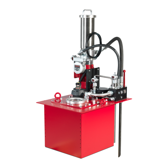
Description of unit Description of unit The OXiStop (OXS) is a tank solution for hydraulic systems with an integrated hydraulically driven degassing and dewatering power unit and continuous separation of solids. The OXS-Lid series represents a tank lid solution for the customer-specific design tanks and contain all of the components required for degassing and the separation of solids. -
Page 22: Achievable Degassing Rate/Residual Water Content
Description of unit Achievable degassing rate/residual water content The achievable degassing rate is: ≈ 8 l/h at 20% air content ≈ 4 l/h at 10% air content ≈ 0.8 l/h at 2% air content The achievable residual water content is ≤ 50ppm (depending on the fluid). The degassing capacity/degassing speed depend, in particular, on the oil type, oil temperature, oil quantity, tank properties, residual air content and the environmental conditions. -
Page 23: Available Sizes
Description of unit Available sizes The unit is available in the following sizes: Installation size Differential operating volume Δ ≤ 30 liters OXS 30LID ≤ 45 liters OXS 45LID ≤ 70 liters OXS 70LID ≤ 150 liters OXS 150LID ≤ 250 liters OXS 250LID ≤... -
Page 24: Unit Components
Description of unit Unit components The unit has the following components: Position overview of unit components: OXiStop OXS-LID Page 24 / 112 MoWa OXS-LID 3992764e en-us 2018-08-10.docx 2018-08-10... - Page 25 Description of unit Item Designation OXS-LID primary body OLF 5 bypass flow filtration unit Clogging indicator at filtration unit OLF5 ContaminationSensor CS (optional) AquaSensor AS (optional) MiniOX (MOX) degassing and dewatering unit Pressure sensor EDS, electric Pressure gauge, visual (optional) Valve and connection block Selector valve 5.93...
-
Page 26: Hydraulic Diagram
Description of unit Hydraulic diagram The unit has the following hydraulic diagram: OXiStop OXS-LID Page 26 / 112 MoWa OXS-LID 3992764e en-us 2018-08-10.docx 2018-08-10... - Page 27 Description of unit Position overview of hydraulic diagram: Item Designation OXS-LID primary body OLF 5 bypass flow filtration unit Clogging indicator at filtration unit OLF5 ContaminationSensor CS (optional) CS.1 Protective screen (optional) AquaSensor AS (optional) 2.42 Suction screen MiniOX (MOX) degassing and dewatering unit Pressure sensor EDS, electric Pressure gauge, visual (optional)
-
Page 28: Dimensions
Description of unit Dimensions The unit is produced in a variety of sizes – the dimensions are given in the following drawing and the accompanying table. The following dimensions are dependent on the size: OXiStop OXS-LID Page 28 / 112 MoWa OXS-LID 3992764e en-us 2018-08-10.docx 2018-08-10... - Page 29 Description of unit OXS-LID Variable dimensions in mm Installation size 625.5 625.5 625.5 1015 1015 1415 1195 -121 1415 1195 -121 OXS-LID Installation size 30/45/70 86.5 605.5 150/250 99.5 82.5 325/500 116.25 1395 OXiStop OXS-LID Page 29 / 112 MoWa OXS-LID 3992764e en-us 2018-08-10.docx 2018-08-10...
-
Page 30: Unit Operating Principle
Unit Operating Principle Unit Operating Principle After the OLF 5 bypass flow filtration unit (2.1) has been switched on, the fluid is pumped from the tank to degassing and dewatering unit (3.1) via the valve and connection block (4.1) and the fluid filter. In degassing and dewatering unit (3.1) the fluid surface is used as a hydraulic piston to create a vacuum and thus remove gases and solid matter from the fluid. -
Page 31: Preparing Installation/Preparing Tank
Preparing installation/preparing tank Preparing installation/preparing tank Prepare the tank according to the following steps: Dimension the tank with sufficient size to allow the OXS-LID to be fully integrated and to avoid dead spaces as much as possible. Ensure that the respective tank securing measures are in place when using hydraulic accumulators in the overall hydraulic system. -
Page 32: Mounting The Unit
Preparing installation/preparing tank Mounting the unit Mount the OXS_LID using an external, detachable threaded connection, air- tight welded threaded bolts or with an air-tight welded connection flange. Secure the screw connection against coming loose, e.g. by using locknuts or similar. Item Designation OXS-LID... -
Page 33: Tightening Sequence
Preparing installation/preparing tank Tightening sequence The screws on the OXS--30/45/70LID are to be tightened as follows: Number of screws n = 26; nominal torque Mn = 7 Nm Tighten screws 1-6 with 20% of the nominal torque. Check plane parallelism. Tighten screws 1-6 with 60% of the nominal torque. - Page 34 Preparing installation/preparing tank The screws on the OXS-150/250LID are to be tightened as follows: Number of screws n = 36; nominal torque Mn = 7 Nm Tighten screws 1-8 with 20% of the nominal torque. Check plane parallelism. Tighten screws 1-8 with 60% of the nominal torque. Tighten screws 1-8 with 105% of the nominal torque.
- Page 35 Preparing installation/preparing tank The screws on the OXS-325/500LID are to be tightened as follows: Number of screws n = 44; nominal torque Mn = 7 Nm Tighten screws 1-16 with 20% of the nominal torque. Check plane parallelism. Tighten screws 1-16 with 60% of the nominal torque. Tighten screws 1-16 with 105% of the nominal torque.
-
Page 36: Installing The Fluid Level Display (Optional/Accessory)
Preparing installation/preparing tank Installing the fluid level display (optional/accessory) We recommend that you install a visual fluid level display on the tank. Use the air-tight welded sleeves for fastening the fluid level indicator. Ensure that bottom connector (7.241) of fluid level indicator (7.24) is mounted below the diaphragm cage. -
Page 37: Making The Hydraulic Connections To The Unit
Preparing installation/preparing tank Making the hydraulic connections to the unit Connect the hydraulic tank to your hydraulic system at the corresponding connections. Electrically clamping the OLF 5 bypass flow filtration unit DANGER Exposed electrical components in the switch cabinet Risk of fatal injury from electrocution ►... -
Page 38: Monitoring The Unit's Sensors/Displays
Monitoring the unit's sensors/displays Monitoring the unit's sensors/displays The hydraulic unit may be fitted with the following clogging indicators and sensors, depending on the design. OXiStop OXS-LID Page 38 / 112 MoWa OXS-LID 3992764e en-us 2018-08-10.docx 2018-08-10... - Page 39 Monitoring the unit's sensors/displays Details for the individual sensors/indicators are given on the following pages: Item Designation For details, see page Visual clogging indicator at the OLF 5 bypass flow filtration unit ContaminationSensor CS on the OLF 5 bypass flow filtration unit (optional) AquaSensor AS on the OLF 5 bypass flow filtration unit (optional) EDS electronic pressure sensor or vacuum...
-
Page 40: Monitoring Unit Function
Monitoring the unit's sensors/displays Monitoring unit function Use the electronic pressure sensor EDS or the optional visual vacuum gauge to monitor the unit function. The vacuum gauge or the pressure sensor on the degassing and dewatering unit is used to monitor the function of the OXiStop and the hydraulic system. Explanations regarding how to interpret the display/measured values are given below. - Page 41 Monitoring the unit's sensors/displays In fault-free operation, the measured pressure oscillates between approx. - 0.98 bar negative pressure and 0.5 bar positive pressure (20 mbar absolute and 1500 mbar absolute). The cycle time can range from 20 to 120 seconds and it is dependent on the fluid temperature and the air content.
- Page 42 Monitoring the unit's sensors/displays There is a direct relationship between the lower pressure measured in the degassing unit and the approximate air content in the oil. lowest negative pressure in mbar (abs) Note that this graph is based on the total gas content in the oil. Additionally, the graph gives the estimated air content only for oils with low water contents (<...
-
Page 43: Fluid Level Indicator, Visual - Min/Max Marking
Monitoring the unit's sensors/displays Fluid level indicator, visual – Min/Max marking Visual fluid level indicator (7.24) is used to monitor and check the diaphragm. The column of fluid in the fluid level indicator corresponds to the current position of the underside of the diaphragm. Accordingly, the higher the column rises, the more the diaphragm is being folded up. -
Page 44: Connecting Electronic Fluid Level/Temperature Sensor Hns
Monitoring the unit's sensors/displays Connecting electronic fluid level/temperature sensor HNS The unit is equipped with a float-based sensor with an integrated fluid level/temperature sensor. The surface of the fluid in the fluid level suction tube corresponds to the current position of the underside of the diaphragm. The sensor is located in the valve block and it is used to monitor the diaphragm stroke and thus the differential operating volume available in the tank. -
Page 45: Connecting Aquasensor As (Optional)
Monitoring the unit's sensors/displays Connecting AquaSensor AS (optional) With the optional AquaSensor, the water saturation of the sucked-in fluid is continuously measured and shown directly on the sensor. The water saturation indicates what percent of maximum possible water is dissolved in the oil. -
Page 46: Connecting Contaminationsensor Cs1000 (Optional)
Monitoring the unit's sensors/displays Connecting ContaminationSensor CS1000 (optional) The optional ContaminationSensor measures the level of solid contamination in the fluid. Example illustration: CS1x2x (with display) Details on connection and the terminal allocations and settings can be found in the instructions for the CS. OXiStop OXS-LID Page 46 / 112 MoWa OXS-LID 3992764e en-us 2018-08-10.docx... -
Page 47: Starting Up The Unit
Starting up the unit Starting up the unit After you have connected the unit and the components hydraulically and electrically as described in the relevant chapters, start up the unit as follows: Check that a suitable filter element is installed in all filter housings. Fill and bleed the unit with oil as described in the chapter "Filling the hydraulic tank with oil (first filling/oil change)"... -
Page 48: Troubleshooting
Troubleshooting Troubleshooting The following errors could arise during operation. The possible causes for the errors are listed below, along with how the errors can be remedied. Error Cause(n) Remedy Degassing unit is Excess air Ensure that the hydraulic failing to degas; the introduction. - Page 49 Troubleshooting Error Cause(n) Remedy The hydraulic Top up the oil – see page 58. system was not filled with sufficient oil. Too much oil on the The hydraulic tank Exchange the diaphragm. inside/on the is overfilled. See page 85 for details. diaphragm The diaphragm is leaking.
-
Page 50: Performing Maintenance
Performing Maintenance Performing Maintenance WARNING Working overpressure Danger of bodily injury ► Switch off the hydraulic system before performing any maintenance work and depressurize the system. The safety of all persons coming into contact with the unit and the availability of the unit for use are dependent on regular servicing and maintenance. -
Page 51: Maintenance Intervals
Performing Maintenance Maintenance intervals The inspection and maintenance work listed here is a necessary condition for ensuring both long service life and error-free operation of the unit. Unit Check the unit for leaks (visual check). Check the screwed fittings to see that they have been properly resecured. - Page 52 Performing Maintenance Check the cables and cable conduits for damage. (Visual inspection) Synchronize the electricity consumption of the motors by measuring with the nominal values on the name plates. Perform an electrical safety inspection in accordance with DIN VDE 0702 and/or corresponding national regulation.
-
Page 53: Filling The Hydraulic Tank With Oil (First Filling/Oil Change)
Performing Maintenance Filling the hydraulic tank with oil (first filling/oil change) This chapter describes how to fill the hydraulic tank for commissioning / oil change or maintenance via the OLF 5 bypass flow filtration unit (2.1). Filling through the OLF 5 bypass flow filtration unit (2.1) ensures that the hydraulic oil is always filled with clean, filtered oil. - Page 54 Performing Maintenance OXiStop OXS-LID Page 54 / 112 MoWa OXS-LID 3992764e en-us 2018-08-10.docx 2018-08-10...
- Page 55 Performing Maintenance To fill the hydraulic tank via the OLF 5 bypass flow filtration unit (2.1), proceed as follows: Fully unscrew screw plug (B.22) to bleed air from the hydraulic tank. Optional: Unscrew the screw plug (Z1) on the "Connection kit for rapid bleeding for OXS"...
- Page 56 Performing Maintenance Switch off the system as soon as the oil level reaches the mark in the hydraulic tank. Move the cylinder into the marked initial position and top it off with oil up to 2/3 full. If necessary, repeat the step several times until the whole hydraulic system is filled with sufficient oil.
- Page 57 Performing Maintenance If the oil level reaches the mark , top up with more oil; for details, see the chapter "Refilling the hydraulic tank with oil" on page If the mark is reached, drain oil off, for details, see chapter "Partially emptying the hydraulic tank" on page 61. 14.
-
Page 58: Refilling The Hydraulic Tank With Oil
Performing Maintenance Refilling the hydraulic tank with oil This chapter describes how to refill the hydraulic tank via the OLF 5 bypass flow filtration unit (2.1). Note that initial filling comes before refilling and that no intake of air caused by the opening of screw plugs, etc. - Page 59 Performing Maintenance OXiStop OXS-LID Page 59 / 112 MoWa OXS-LID 3992764e en-us 2018-08-10.docx 2018-08-10...
- Page 60 Performing Maintenance To refill oil in the hydraulic tank, proceed as follows: Unscrew the screw plug (B.08) on the valve block). Mount a suction hose to this connection (G ¾") and insert the other end into an unpressurized external oil container to suck out the oil. Open the selector valve (4.7) by switching from position (a) to position (b).
-
Page 61: Partially Emptying The Hydraulic Tank
Performing Maintenance Partially emptying the hydraulic tank This chapter describes how to partly empty the hydraulic tank via the OLF 5 bypass flow filtration unit (2.1), e.g. with overfilling, etc. OXiStop OXS-LID Page 61 / 112 MoWa OXS-LID 3992764e en-us 2018-08-10.docx 2018-08-10... - Page 62 Performing Maintenance Empty the tank partially as follows: Unscrew the screw plug (B.09) on the valve block. Mount a return hose to this connection (G ½") and insert the other end into an unpressurized external oil container to collect the oil. Switch on the OLF 5 bypass flow filtration unit (2.1) on.
-
Page 63: Completely Emptying The Hydraulic Tank For Transport, Oil Change, Etc
Performing Maintenance Completely emptying the hydraulic tank for transport, oil change, etc. This chapter describes how to completely empty the hydraulic tank for transport, oil change or maintenance via the OLF 5 bypass flow filtration unit (2.1). OXiStop OXS-LID Page 63 / 112 MoWa OXS-LID 3992764e en-us 2018-08-10.docx 2018-08-10... - Page 64 Performing Maintenance Empty the hydraulic tank along with the components without the degassing unit as follows: Fully unscrew the screw plug (B.22) on the valve block to bleed air from the hydraulic tank. Drain the components, e.g. the OLF 5 bypass flow filtration unit (2.1), heat exchanger with pump and return line filter at the respective drain plugs.
-
Page 65: Emptying The Degassing Unit
Performing Maintenance Emptying the degassing unit The degassing unit (3.1) holds ≈ 1.5 l oil. Empty the degassing unit as follows: Unscrew the screw plug (X) for emptying completely. Collect the escaping fluid in a suitable container and dispose of it in an environmentally friendly manner. -
Page 66: Manual Bleeding During Commissioning (Optional/Accessories)
Performing Maintenance Manual bleeding during commissioning (optional/accessories) The free air can be removed rapidly from the tank during commissioning with the aid of the "Connection kit for rapid bleeding for OXS" Ball valve "closed" Ball valve "open" Fully unscrew the screw plug (B.22) on the valve block to bleed air from the hydraulic tank and apply the "Connection kit for rapid bleeding for OXS"... -
Page 67: Checking The Clogging Indicator On The Breather Filter
Performing Maintenance Checking the clogging indicator on the breather filter The OLF 5 bypass flow filtration unit is equipped with an optical clogging indicator (6.45) for monitoring the degree of contamination. Exchange the filter element when the clogging indicator displays 50 mbar. See page 68 for details. -
Page 68: Replacing The Breather Filter Element
Performing Maintenance Replacing the breather filter element Change the filter element at the breather filter at the same intervals as for the filter element at the bypass flow filter unit OLF 5 at least once a year. If the unit is in a very dusty/damp environment, the replacement intervals shorten accordingly. - Page 69 Performing Maintenance Replace the filter element of the breather filter BF5/52 as follows: Screw the nut (6.46) and the washer (6.47) out of the breather filter fully. Remove the cover (6.41). Remove used filter element (6.42) and dispose of it in an environmentally correct manner.
-
Page 70: Checking The Visual Clogging Indicator On The Bypass Flow Filtration Unit
Performing Maintenance Checking the visual clogging indicator on the bypass flow filtration unit The OLF 5 bypass flow filtration unit is equipped with an optical or electric clogging indicator for monitoring the degree of contamination. Replace the filter element when the red marking becomes visible in the clogging indicator. -
Page 71: Replace The Filter Element On The Olf 5 Bypass Flow Filtration Element
Performing Maintenance Replace the filter element on the OLF 5 bypass flow filtration element Replace the filter element as described below: Switch off the system and ensure that it will not be possible for the unit to be switched back on during the maintenance work. - Page 72 Performing Maintenance Remove the dirt catch tray. Remove the filter element from the filter housing cover. Dispose of the old filter element according to local regulations and guidelines. Clean the removed parts and examine them for any possible damage. Check the O-ring on the filter bowl cover for damage.
- Page 73 Performing Maintenance Fasten the dirt catch tray to the bottom end of the filter element. 10. Lift the filter element with the cover and dirt catch tray into the filter housing. Observe correct placement of the O-ring on the cover while doing so. Fasten the cover with the tension clamp.
- Page 74 Performing Maintenance flow filtration unit" on page 77. 15. Fill the tank with the same volume that you removed to change the filter element. For details, refer to chapter "Refilling the hydraulic tank with oil" on page 58. 16. Check the fluid filter for leaks while in operation.
-
Page 75: Replace Protective Screen On The Olf 5 Bypass Flow Filtration Unit
Performing Maintenance Replace protective screen on the OLF 5 bypass flow filtration unit NOTICE Protective screen missing / operation without the protective screen The ContaminationSensor clogged / blocked ► Never operate the unit without a protective strainer. ► Replace the protective strainer regularly. A protective strainer is installed upstream from the ContaminationSensor to protect it from blockage. - Page 76 Performing Maintenance To replace the protective screen, proceed as follows: Switch off the unit/all components. Empty the OLF 5 bypass flow filtration unit, as described in chapter "Replace the filter element on the OLF 5 bypass flow filtration element" on page 71. Loosen the screw connection and remove protective strainer (CS.1) between the two O-rings (CS.2).
-
Page 77: Clean/Replace The Suction Strainer On The Olf 5 Bypass Flow Filtration Unit
Performing Maintenance Clean/replace the suction strainer on the OLF 5 bypass flow filtration unit NOTICE Suction strainer missing / operating without a suction strainer ContaminationSensor, MOX, pump blocked/clogged ► Never operate the unit without a suction screen. ► Clean the suction strainer regularly A suction strainer is installed upstream to prevent the pump from becoming blocked. - Page 78 Performing Maintenance To clean/replace the suction strainer, proceed as follows: Switch off the unit/all components. Empty the OLF 5 bypass flow filtration unit, as described in chapter "Replace the filter element on the OLF 5 bypass flow filtration element" on page 71. Loosen hose assembly (2.5) and remove the suction strainer (2.42).
-
Page 79: Bleeding The Olf 5 Bypass Flow Filtration Unit
Performing Maintenance Bleeding the OLF 5 bypass flow filtration unit WARNING Hot fluid Risk of burns ► Make sure that hot fluid can exit when bleeding. NOTICE Air in the OLF 5 bypass flow filtration unit The filter element is not utilized completely ►... -
Page 80: Checking/Setting The Electronic Pressure Switch (Eds)
Performing Maintenance Checking/setting the electronic pressure switch (EDS) Before the unit is started up, and every time the electronic pressure switch EDS has been replaced, check the settings in accordance with the following specifications. Check or configure the electronic pressure sensor EDS with the following alarm settings: Alarm 1: Error MOX (when a pressure higher than 1200 mbar is... - Page 81 Performing Maintenance Check or configure the electronic pressure sensor EDS with the following factory settings: Display Possible values Setting 0.00 … 99.99 99.99 0.00 … 99.99 0.00 … 99.99 0.00 … 99.99 S.P.1 S.P.2 0 … 300 SLOW Fast MEDI FAST Free FREE...
-
Page 82: Checking/Setting Electronic Fluid Level/Temperature Sensor Hns
Performing Maintenance Checking/setting electronic fluid level/temperature sensor HNS The unit is equipped with a float-based sensor with an integrated fluid level/temperature sensor. The operating principle of the fill level sensor and range of the differential operating volume is shown in the following illustration and table. Check the fluid level/temperature sensor HNS. - Page 83 Performing Maintenance OXS- Maximum oil Minimum oil level level Lo.1 Hi.1 31.5 cm 7.6 cm 362 mm 5 mm 520 mm 42.5 cm 7 cm 472 mm 5 mm 630 mm 63.5 cm 7 cm 682 mm 5 mm 840 mm 42.5 cm 7 cm 472 mm...
-
Page 84: Recalibrating The Contaminationsensor
Performing Maintenance Recalibrating the ContaminationSensor For recalibration, send the ContaminationSensor to an establishment authorized by HYDAC. For details, instructions for the ContaminationSensor. Testing the AquaSensor AS Check the AquaSensor annually with the calibration and adjustment set. The Part no. for ordering can be found in the spare parts list. -
Page 85: Replacing The Diaphragm
Performing Maintenance Replacing the diaphragm The service life of the diaphragm is dependent on the fluid temperature – for details see chapter "Technical Data" on page 101. Replace the diaphragm after the specified time to avoid malfunction. Removing the diaphragm OXiStop OXS-LID Page 85 / 112 MoWa OXS-LID 3992764e en-us 2018-08-10.docx... - Page 86 Performing Maintenance To remove the diaphragm, proceed as follows: Switch off the unit and all its components. Drain the unit completely – for details see the chapter "Completely emptying the hydraulic tank for transport, oil change, etc." on page Remove the piping between valve block and diaphragm cover (6.2). Loosen all nuts (6.6) and washers (6.5) of the diaphragm cover (6.2).
-
Page 87: Installing The Diaphragm
Performing Maintenance Installing the diaphragm OXiStop OXS-LID Page 87 / 112 MoWa OXS-LID 3992764e en-us 2018-08-10.docx 2018-08-10... - Page 88 Performing Maintenance To install the diaphragm proceed as follows: Clean sealing surface (X) of diaphragm (6.1) completely. The sealing surface must be free of old sealant residue. Apply a thin, even layer of HYLOMAR M sealant around sealing surface (X). The part no. can be found in the spare parts list. Observe the bleed time in accordance with the operating instructions.
- Page 89 Performing Maintenance Now pull the sealing collar of diaphragm (6.1) carefully and evenly over the threaded bolts. Smooth down the sealing material under the sealing collar, working carefully from the inside to the outside. No sealant is permitted in the working area of the diaphragms.
-
Page 90: Taking The Unit Out Of Operation
Taking the unit out of operation Taking the unit out of operation Empty the unit completely, including all of its components, before putting it out of service, as described on page 63. Disconnect all electrical and hydraulic connections from and to the unit. Store the unit in a clean, dry (non-condensing) space. -
Page 91: Customer Service/ Service
Phone: +49 (0) 6897 509 1174 Fax: +49 (0) 6897 509 9046 E-mail: filtersystems@hydac.com Our HYDAC Servicenter offers you these tasks within agreed-upon time frames and at fixed prices. HYDAC SERVICE GMBH Friedrichstaler Straße 15a, Werk 13 66540 Neunkirchen-Heinitz Germany... -
Page 92: Spare Parts List
Spare parts list Spare parts list Only use original spare parts and accessories to ensure safe and reliable operation of the unit. When ordering spare parts, always provide the complete designation (type, part no., serial no., year of construction). OXiStop OXS-LID Page 92 / 112 MoWa OXS-LID 3992764e en-us 2018-08-10.docx 2018-08-10... - Page 93 Spare parts list OXiStop OXS-LID Page 93 / 112 MoWa OXS-LID 3992764e en-us 2018-08-10.docx 2018-08-10...
- Page 94 Spare parts list Item Designation Part no. OLF-5/10-TV-370-N-Z-BM/-10 Without filter 4376254 element OLFCM-5/10-TV-370-N-Z-BM/-ACD-10 4376344 Screw connection 607723 2.41 O-ring 604073 2.42 Suction screen 37575 Hose assembly 6181412 2.55 Screw connection 6019771 2.65 Hose assembly 6130504 Threaded coupling 680107 MOX-1-N/-OXS 3519092 Washer 6112446 Hex.
- Page 95 Spare parts list Item Designation p/no. Replacement diaphragm set, comprised of: 1x diaphragm 1x HYLOMAR M sealing compound (80 ml) 1x assembly set Replacement diaphragm set to OXS-30 4228462 Replacement diaphragm set to OXS-45 4228463 Replacement diaphragm set to OXS-70 4228464 Replacement diaphragm set for OXS-150 4228495...
- Page 96 Spare parts list OXS-LID primary body to OXS-30 4246254 OXS-LID primary body to OXS-45 4251850 OXS-LID primary body to OXS-70 4251851 OXS-LID primary body to OXS-150 4239964 OXS-LID primary body to OXS-250 4242909 OXS-LID primary body to OXS-325 4242913 OXS-LID primary body to OXS-500 4240250 5.93 Fluid level/temperature sensor HNS...
- Page 97 Spare parts list Designation Material p/no. Sealing compound HYLOMAR M 3947926 Tank seal Flat gasket for OXS-30/45/70 4251854 Flat gasket for OXS-150/250 3905986 Flat gasket for OXS-325/500 3914649 OLF 5 bypass flow filtration unit Filter element, 2 µm N5DM002 349494 Filter element, 5 µm N5DM005 3068101...
-
Page 98: Accessories
Accessories Accessories We provide the following fluid level displays as accessories for the unit: Not that the upper connector (7.25) needs to be glued in. Item Designation Part no. OXiStop OXS-LID Page 98 / 112 MoWa OXS-LID 3992764e en-us 2018-08-10.docx 2018-08-10... - Page 99 Accessories 7.25 Bolt, M12 3925870 Fill level indicator set for 4071801 OXS-30, comprised of: 1x fluid level indicator (7.24), L = 381 mm 1x bolt (7.241) 2x sealing washer (7.242) 1x bolt (7.25) Fill level indicator set for 4073619 OXS-45/150/325, comprised of: 1x fluid level indicator (7.24), L = 500 mm 1x bolt (7.241) 2x sealing washer (7.242)
-
Page 100: Oxistop Oxs-Lid En
Accessories We offer the following connection kit as an accessory for the unit: Part no. Designation 4243219 Connection kit for rapid bleeding for OXS OXiStop OXS-LID Page 100 / 112 MoWa OXS-LID 3992764e en-us 2018-08-10.docx 2018-08-10... - Page 101 Technical Data Technical Data The unit has the following technical data: Hydraulic data Installation size Differential Empty weight Volume ≤ 30 liters OXS-30LID approx. 66 kg ≤ 45 liters OXS-45LID approx. 70 kg ≤ 70 liters OXS-70LID approx. 76 kg ≤...
- Page 102 Technical Data General data Sealing material Diaphragm material ≈ 6 years @ ≤60°C fluid Typical lifetime of the diaphragm* temperature (dependent on the fluid ≈ 2 years @ ≥60°C fluid temperature) temperature Permissible ambient temperature –20 to 40 °C range** Permitted storage temperature 0 …...
- Page 103 Model code Model code The unit is ordered in accordance with the following model code: OXS - 30LID - N - 1 - Z - Z - 2 - 2 - ACD - /- Product OXS = OXiStop Differential Volume 30LID = Differential operating volume ≤30 l...
- Page 104 Index Index filtration ..18, 25, 27, 30, 37, 39, 47, 48, 51, 53, 55, 56, 58, 60, 61, 62, 63, 64, 67, 70, 71, 73, 74, 75, 76, 77, 78, 79, 97 Accessories ............98 accident prevention ........10, 14 ambient temperature ......
- Page 105 Index Transport .............. 13 transporting ............13 Troubleshooting ..........13, 48 select ..............7 Service ..............91 setting ..........44, 47, 80, 82 Signal word ............9, 10 signal words............10 Viscosity ............... 19 Spare part ............. 92 Spare parts ............92 Spare parts list ............
- Page 112 HYDAC FILTER SYSTEMS GMBH Industriegebiet Postfach 1251 66280 Sulzbach/Saar 66273 Sulzbach/Saar Germany Germany Tel: +49 (0) 6897 509 01 Central Fax: +49 (0) 6897 509 9046 Technical Department Fax: +49 (0) 6897 509 577 Sales Internet: www.hydac.com E-mail: filtersystems@hydac.com...
Need help?
Do you have a question about the OXiStop OXS LID Series and is the answer not in the manual?
Questions and answers