
Summary of Contents for DAIICHI SFLC-110L
- Page 1 SFLC-211-185 INSTRUCTION MANUAL POWER LINE MULTI-METER SFLC-110L [ 1φ2W / 1φ3W / 3φ3W ANALOG OUTPUT ] HARDWARE MODEL B [ Green backlight ] HARDWARE MODEL E [ White backlight ]...
- Page 2 SFLC-211-185 Introduction Thank you for your purchase of our product. Read this instruction manual carefully before installation, wiring, and using this product. Keep this instruction manual handy for reference at any time. Have a contact with us or sales agent in case that this instruction manual is lost or damaged. <Caution>...
- Page 3 SFLC-211-185 Other precaution Don't mount or store this unit in the following environment. 1 Places where corrosive gas (SO S / etc.)( ) is generated. Places where dust is generated. Places with much vibration and shock. 2 Places with influence of external magnetic field ( 1...
- Page 4 SFLC-211-185 The precaution for use. 1. Environment of usage and storage. Don’t mount or store this product in the following environments. If the unit becomes defective due to the use in an environment other than specified, it may be repaired for pay even during its warranty period (one year after the date of delivery).
- Page 5 SFLC-211-185 5. Setting This unit requires setting and confirmation of the measuring range, etc. before use. Wrong setting, if any, causes malfunction of the unit. If setting should be wrong, neither measurement nor output becomes correct. Carefully read the instruction manual before setting the unit. ■...
- Page 6 SFLC-211-185 3-phase 3-wire Single-phase 3-wire Single-phase № Setting item 110V input 220V input (R-B-W) 110V input 220V input Output factor 1 A(Y) A(R) Output factor 2 V(RY) V(RW) Output factor 3 Analog output Current 100.0% 100.0% 100.0% Output 5 intrinsic Active power 100.0%...
- Page 7 SFLC-211-185 6. Operation Be careful with the following cautions during use. Use the input within the rated range. Be careful since negligence of this caution may cause troubles of the unit. There is a function to hold the maximum value and the minimum value with a measurement factor in this product. A blackout is guaranteed and this value isn't also cleared by a power supply reset.
-
Page 8: Table Of Contents
SFLC-211-185 Content 1. Product outline ・・・・・・・・・・・・・・・・・・・・・・・・・・・・・・・・・・・・・・・・・・・・・・・・・・・・・・・・・・・ 8 1.1 Usage of product ・・・・・・・・・・・・・・・・・・・・・・・・・・・・・・・・・・・・・・・・・・・・・・・・・・・・・・・ 8 1.2 Features of product ・・・・・・・・・・・・・・・・・・・・・・・・・・・・・・・・・・・・・・・・・・・・・・・・・・・・ 8 1.3 Composition of type ・・・・・・・・・・・・・・・・・・・・・・・・・・・・・・・・・・・・・・・・・・・・・・・・・・・・ 8 2. The name and function of each part ・・・・・・・・・・・・・・・・・・・・・・・・・・・・・・・・・・・・・・・・ 9 3. Preparation 3.1 Installation ・・・・・・・・・・・・・・・・・・・・・・・・・・・・・・・・・・・・・・・・・・・・・・・・・・・・・・・・・・・ 10 3.2 Connections ・・・・・・・・・・・・・・・・・・・・・・・・・・・・・・・・・・・・・・・・・・・・・・・・・・・・・・・・・・・・... -
Page 9: Product Outline
LCD can be chosen from 2 kinds, the type to see from the top and the type to see from the bottom. (Please designate it at an order.) 1.3 Composition of type TYPE Specification code SFLC-110L- □□□□□-□□□ Installation position 1:For an upper installation. 2:For an lower installation. Option... -
Page 10: The Name And Function Of Each Part
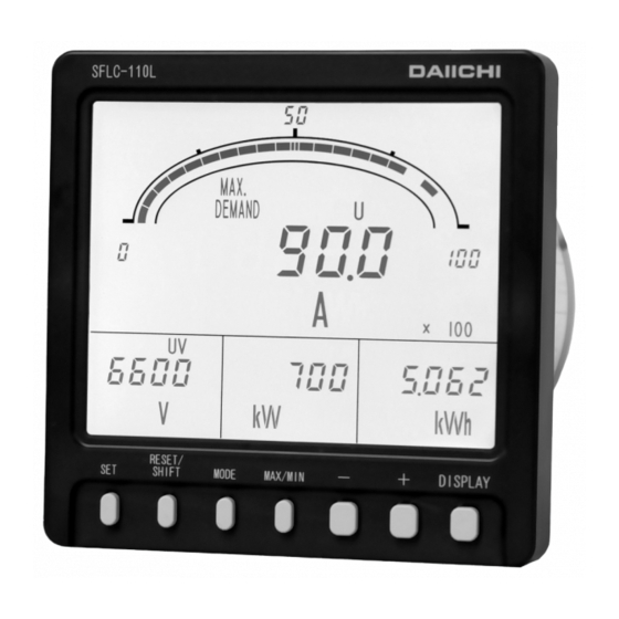
SFLC-211-185 2. The name and function of each part Bar graph display Scale markings The measurement value of the main monitor It sets automatically by measurement-range is indicated by the analog. setting. (Setting which does bar graph display Upper limit (or lower limit) setting index of the measurement value of sub monitor An upper limit (or lower limit) set point is is also possible.) -
Page 11: Preparation
SFLC-211-185 3. Preparation 3.1 Installation Mount the unit by the attached M5 nuts to a panel of thinner than 10mm, referring to the following external dimensions drawing and panel cutout. Fasten these nuts with tightening torque 2.0~2.5N・m. ● Dimension diagram ●... -
Page 12: Connections
SFLC-211-185 3.2 Connections Please perform connection after referring to the following wiring diagram. ● Connection drawing ( (1) 1φ2W,Analog output. (2) 1φ3W, Analog output. AUX.SUPPLY AUX.SUPPLY ANALOG OUTPUT 1 ANALOG OUTPUT 1 ANALOG OUTPUT 2 ANALOG OUTPUT 2 ANALOG OUTPUT 3 ANALOG OUTPUT 3 PULSE OUTPUT PULSE OUTPUT... -
Page 13: Operation
SFLC-211-185 4. Operation ● The function of switch Switch Function The integrated value of electric energy is changed to the usual display and an enlarged display. If it continues pushing 3 seconds or more, it will change to setting mode. In setting mode, it is used for the determination of a set point. -
Page 14: The Screen Change And Function By Switch Operation
SFLC-211-185 4.1 The screen change and function by switch operation. This product changes various screens by switch operation. Here, the change step of the screen by switch operation is explained. Wh,varh factor display Electric-energy Conditions: integrated-value At manual reset setting enlarged display No operation, Alarm reset... -
Page 15: The Kind Of Display
SFLC-211-185 4.2 The kind of display 4.2.1 Measurement display The change of the measurement display element of the main monitor by switch operation and the change of the phase / line display of current / voltage is possible (temporarily). In a general measurement display, if switch operation is not performed for 10 minutes after changing a display element, it returns to the original measurement display element automatically. -
Page 16: Alarm Detection Display
SFLC-211-185 Measurement Measurement Example of display Note Example of display Note factor factor Power factor Frequency cosφ LEAD display Watt-hour Watt-hour “- (Power (Power (minus)” receiving) transmission) display var-hour var-hour (Power (Power “LAG” “LEAD” receiving, receiving, display display LAG) LEAD) varh(LAG) varh(LEAD) var-hour... - Page 17 SFLC-211-185 ・The example of a display at the case of the detection in each alarm factor. In case the alarm factor is indicating by measurement at the main monitor or the sub monitor, a measurement value constitutes a blinking display. The displays after an alarm return.
-
Page 18: Setting Display
SFLC-211-185 4.2.3 Setting display It is the display at the case of various setting. There are three types of setting modes according to the contents of a setting. Operation and the contents of setting (detail) in setting mode, please refer to "5 Setting". ①... -
Page 19: Operation
SFLC-211-185 4.3 Operation 4.3.1 The main monitor display-element change The measurement display element of the main monitor is changed. A change is performed by + -. A measurement display and maximum display,minimum display can also perform this operation. After changing a measurement display element, if a switch is not operated for 10 minutes, it will return to the original measurement display element automatically. -
Page 20: Enlarged Display Of Integral Power Consumption
SFLC-211-185 4.3.3 Enlarged display of integral power consumption. In case electric energy is being displayed by the general measurement display, an electric-energy display is changed to a normal display (5 digits of integers), and an enlarged display (2 digits integer + below decimal point, 3 digits). -
Page 21: Setting Mode
SFLC-211-185 4.3.5 Setting mode Various kinds of setting are performed. Setting mode is three types, and operations are different. DISPLAY is pushed in case it returns to the original measurement display. And, if a switch is not operated for 10 minute after a set point check, it will return to the original measurement display automatically. Operation and the contents of setting (detail) in setting mode, please refer to "5 Setting". -
Page 22: Reset
SFLC-211-185 4.3.6 Reset Various kinds of reset are performed. The kind of reset is as follows and operations are different, respectively. Reset of integral power consumption (zero clear), Reset of maximum value and minimum value (it updates to the instantaneous value at the time), Alarm-output reset (OFF of an alarm output (at the case of manual reset setting)). - Page 23 SFLC-211-185 (2) Alarm reset In case an alarm return method is set to “HOLD (manual return)”, an alarm output is reset (output OFF). (With an alarm-output option) However, an output is not turned off by this operation, in case an alarm continues and it has caused. And, this operation is unnecessary if an alarm return method is set as "AUTO (automatic return)".
- Page 24 SFLC-211-185 b) All reset of maximum value and minimum value. It resets all the maximum values and minimum values. In addition, setting can perform same operation in external operation input. Please refer to "5.3.2 Setting mode 2 (4) external operation input setting" for the setting method. Please refer to "6.3 Option"...
-
Page 25: Setting
SFLC-211-185 5. Setting < Caution > When changing the input circuit setting, please be sure to perform a setup from an input circuit setting in the setting mode 3. After changing the other setting, when the input circuit setting is changed the set value returns to default value (default value of a changed input circuit). - Page 26 SFLC-211-185 Setting mode 2. Function table (1) Setting Important Function Functional description Default setting Page setting 3φ3W 6600V Sets the voltage-measurement range Voltage range 1φ3W 110.0V ○ 44~47 (primary voltage). 1φ2W 3300V 3φ3W 4 digits Digit number of voltage Sets the digit number of voltage range. 1φ3W 4 digits 44~47...
- Page 27 SFLC-211-185 Setting mode 2. Function table (2) Setting Important Function Functional description Default setting Page setting Sets the analog output sensitivity (% 225A Active power output of a rated input power value to an output 100.0% intrinsic sensitivity upper limit) of active power. Sets the analog output sensitivity (%...
- Page 28 SFLC-211-185 Setting mode 3. Function table Setting Important Function Functional description Default setting Page setting 3φ3W 3φ3W Input circuit phase line Sets the input circuit or phase line. 1φ3W 1φ3W(R-B-W) ○ change 1φ2W 1φ2W 3φ3W 110V Sets the input voltage or phase voltage Input voltage 1φ3W 300V...
-
Page 29: Setting Table
SFLC-211-185 5.2 Setting table A setting item changes by the specification of a product, or the existence of an option. (1) Important setting Each parenthesized number shows a setting number and this number is displayed on the setting screen. Items Setting and operation procedures Page Press SET and DISPLAY together for longer than 3 seconds... - Page 30 SFLC-211-185 Items Setting and operation procedures Page Press SET and RESET/SHIFT together for longer than 3 seconds Press MODE Sets the output (211) (221A) factor of pulse Press MODE Select an output factor by + and - Press SET output. (231P) (231P) Selected output factor is entered...
- Page 31 SFLC-211-185 (2) A combination except a display pattern. Each parenthesized number shows a setting number and this number is displayed on the setting screen. Items Setting and operation procedures Page Press SET for longer than 3 seconds Press RESET/SHIFT Sets the display (111) (112) factor of main...
- Page 32 SFLC-211-185 (4) Setting of reactive power measurement range. Each parenthesized number shows a setting number and this number is displayed on the setting screen. Items Setting and operation procedures Page Press SET and RESET/SHIFT together for longer than 3 seconds (211) Press RESET/SHIFT Press RESET/SHIFT...
- Page 33 SFLC-211-185 (7) Setting of current display intrinsic sensitivity. Each parenthesized number shows a setting number and this number is displayed on the setting screen. Items Setting and operation procedures Page Press SET and RESET/SHIFT together for longer than 3 seconds (211) Sets the display Press RESET/SHIFT...
- Page 34 SFLC-211-185 Items Setting and operation procedures Page Press SET and RESET/SHIFT together for longer than 3 seconds (211) Press RESET/SHIFT Press RESET/SHIFT Press RESET/SHIFT (212) (213) (214) Press RESET/SHIFT Press RESET/SHIFT Press RESET/SHIFT Sets the digit (215) (216) (217) number of 44~...
- Page 35 SFLC-211-185 (10) Setting of alarm output. Each parenthesized number shows a setting number and this number is displayed on the setting screen. Items Setting and operation procedures Page Press SET for longer than 3 seconds Press MODE Press RESET/SHIFT Sets the return (111) (121AL) (122AL)
-
Page 36: Setting In Detail Explanation
SFLC-211-185 (13) Backlight setting Each parenthesized number shows a setting number and this number is displayed on the setting screen. Items Setting and operation procedures Page Press SET for longer than 3 seconds Press MODE Press MODE Press MODE (111) (121AL) (131H) Sets the action of... - Page 37 SFLC-211-185 (1) 111~116 Display combination setting ● 3-phase 3-wire Sub monitor Sub monitor Sub monitor № Pattern № Main monitor Bar graph (Left) (Center) (Right) Pattern 1 A(Y) V(RY) A(Y) Pattern 2 A(Y) V(RY) cosφ A(Y) Pattern 3 A(Y) V(RY) A(Y) Pattern 4 DA(Y)
- Page 38 SFLC-211-185 ● Single-phase 3-wire ( Sub monitor Sub monitor Sub monitor № Pattern № Main monitor Bar graph (Left) (Center) (Right) Pattern 1 A(R) V(RW) A(R) Pattern 2 A(R) V(RW) cosφ A(R) Pattern 3 A(R) V(RW) A(R) Pattern 4 DA(R) V(RW) MDA(R) MDA+DA(R)
- Page 39 SFLC-211-185 ● Single-phase 2-wire Sub monitor Sub monitor Sub monitor № Pattern № Main monitor Bar graph (Left) (Center) (Right) Pattern 1 Pattern 2 cosφ Pattern 3 Pattern 4 MDA+DA Pattern 5 MDA+DA Pattern 6 Pattern 7 cosφ Pattern 8 Pattern 9 MDW+DW Pattern 10...
- Page 40 SFLC-211-185 Display combination setting MAX/MIN RESET/SHIFT RESET/ RESET/ RESET/ RESET/ RESET/ Combination SHIFT SHIFT Sub monitor SHIFT Sub monitor SHIFT Sub monitor SHIFT Bar graph Main monitor MAX/MIN MAX/MIN MAX/MIN MAX/MIN MAX/MIN display (Left) (Center) (Right) factor Pattern 1 A(Y):5 V(RY):1 W:13 Wh:18...
- Page 41 SFLC-211-185 ◆ 111 Combination display New setting Select the factors to be measured and monitored by 4 digital displays out of combination patterns. Now setting Set values are updated by SET . Setting № ◆ 112~115 Main monitor, Sub monitor (left), Sub monitor (center), Sub monitor (right) Sets these items for a display configuration other than combination patterns.
- Page 42 SFLC-211-185 (3) 131H~135 Demand detection setting The next operation method is setting. Demand current, Demand power, High-alarm value, Time-interval, Power-factor, Demand power operation method. 131H 133H MAX/MIN MAX/MIN Demand current Demand current Demand power RESET/ MAX/MIN RESET/ time interval upper limit upper limit SHIFT SHIFT...
- Page 43 SFLC-211-185 (4) 141H~142L Instant measurement detection setting An upper limit low-alarm value is set by instant measurement (voltage factor). 141H 142L MAX/MIN MAX/MIN New setting Now setting Instant measurement Instant measurement RESET/ RESET/ voltage upper limit voltage lower limit SHIFT SHIFT ◆...
-
Page 44: Setting Mode 2
SFLC-211-185 5.3.2 Setting mode 2 SET and RESET/SHIFT 3 seconds 211~21D DISPLAY Measurement range setting MODE 221A~227A DISPLAY Analog output setting MODE 231P~232P DISPLAY Pulse output setting MODE Display mode DISPLAY External operation input setting MODE 251~25C DISPLAY Measurement display ON/OFF setting MODE 261~262 DISPLAY... - Page 45 SFLC-211-185 (1) 211~21D Measurement range setting Sets the measurement range of each measurement factor. MAX/MIN MAX/MIN MAX/MIN MAX/MIN Digit number Digit number Current display Voltage of voltage of current Current range intrinsic RESET/ RESET/ RESET/ RESET/ range range range SHIFT SHIFT SHIFT SHIFT...
- Page 46 SFLC-211-185 ◆ 213 Current range Sets the current range (primary current). Change of this setting also sets the measurement range of active power and reactive power automatically simultaneously. Selection by + and - , set value is updated by SET . Default setting:100.0A (3φ3W), 500.0A (1φ3W), 50.00A (1φ2W) Current-measurement range 750A...
- Page 47 SFLC-211-185 ◆ 216 Active power polarity A swing display of active power meter can be selected from P (one-way deflection) and - (both deflection). Selection by + and - , set value is updated by SET . Default setting:P (one-way deflection) New setting +...
- Page 48 SFLC-211-185 ◆ 21A Digit number of reactive power range New setting Sets the digit number of reactive power range. Selection by + and - , set value is updated by SET . Default setting:4 digits The unit may be changed if the number of digits is changed. Example) 1000kvar 1.00Mvar Now setting...
- Page 49 SFLC-211-185 (2) 221A~227A Analog output setting 【With option】 Various setting of analog output is performed. 224A 221A 222A 223A MAX/MIN MAX/MIN MAX/MIN Current output Ao1 output Ao2 output Ao3 output intrinsic RESET/ RESET/ RESET/ factor factor factor SHIFT SHIFT SHIFT sensitivity RESET/ SHIFT...
- Page 50 SFLC-211-185 (3) 231P~232P Pulse output setting 【With option】 Various setting of a pulse output is performed. MAX/MIN MAX/MIN 231P 232P Pulse output factor Pulse unit RESET/ RESET/ New setting SHIFT SHIFT Setting No. Now setting ◆ 231P Pulse output factor, Sets the output factor of pulse output.
- Page 51 SFLC-211-185 (5) 251~25C Measurement ON/OFF setting Measurement display ON/OFF setting of each measurement factor is performed. Selection by + and - , set value is updated by SET . Default setting:ON (All measurement factors) New setting MAX/MIN MAX/MIN MAX/MIN Setting No. Now setting Demand Voltage...
-
Page 52: Setting Mode 3
SFLC-211-185 5.3.3 Setting mode 3 SET and DISPLAY 3 seconds 311~312 DISPLAY Input circuit setting MODE DISPLAY Display mode Tidal current measurement setting MODE 331~336 DISPLAY Analog output adjustment MODE Setting mode 3 Setting mode 3 is selected by pressing SET and DISPLAY switches continuously for longer than 3 seconds. Pushing MODE switch performs movement of setting item. - Page 53 SFLC-211-185 (1) 311~312 Input circuit setting Sets the input circuit and phase wire and input voltage / phase-voltage full scale. MAX/MIN MAX/MIN Input circuit phase Input voltage RESET/ RESET/ wire change SHIFT SHIFT ◆ 311 Input circuit phase wire change Sets the input circuit and phase wire (1φ3W).
- Page 54 SFLC-211-185 (2) 321 Tidal current measurement setting Sets the with or without of tidal current measurement. ◆ 321 Tidal current measurement By measurement of reactive power and a power-factor, New setting 0 (general measurement) or 1 (tidal current measurement which was conscious of power transmission/power Now setting receiving) can be selected.
- Page 55 SFLC-211-185 (3) 331~336 Analog output adjustment 【With option】 The bias and span of each analog output are adjusted. MAX/MIN MAX/MIN Ao1 BIAS Ao1 SPAN Ao2 BIAS RESET/ RESET/ adjustment adjustment adjustment MAX/MIN SHIFT SHIFT RESET/SHIFT RESET/SHIFT RESET/ RESET/ MAX/MIN SHIFT SHIFT Ao3 SPAN Ao3 BIAS...
-
Page 56: Specification
SFLC-211-185 6. Specification 6.1 Specification and intrinsic error. Input circuit Input 3-phase 3-wire AC110V,220V common use. AC5A 50/60Hz Single-phase 2-wire Single-phase 3-wire AC100-200V ( ), AC5A 50/60Hz Note ( ) The rated voltage of each phase and W phase is 100V. However, the full scale of a bar graph is 300V. Intrinsic error ( Maximum Minimum... - Page 57 SFLC-211-185 Item Specification Bar graph Bar graph display of the main-monitor factor is done. (Watt-hour and var-hour exclude) display A display of a sub monitor factor can also be set. Current, Voltage :Effective value computing type. Demand ammeter :Arithmetic method according with bimetallic type. Demand power meter:Arithmetic method according with bimetallic type, or average value within the Operating demand time limit.
-
Page 58: Performance
SFLC-211-185 6.2 Performance. Item Specification Accuracy Reference to measure specification and accuracy Accuracy of bar graph ±10% (% for span) Influence by Within accuracy by 23±10℃. temperature JIS C 1102-1:2007 ,JIS C 1102-2,-3,-4,-5,-7:1997 Compliance standard JIS C 1111:2006 ,JIS C 1216-1:2009 ,JIS C 1263-1:2009 JIS C 1010-1:2005 CATⅢ... - Page 59 SFLC-211-185 Item Specification (1) Oscillatory surge voltage If a vibration damping waveform (1~1.5MHz, Peak voltage:2.5~3kV) is repeated and added, a measurement error should be within ±10%. And, there needs to be no malfunction. Voltage input circuit (Normal / Common), Current input circuit (Common), Auxiliary supply circuit (Normal / Common) (2) Square wave impulse noise If a noise (1μs, 100ns width) is repeated and added, a measurement error should...
- Page 60 SFLC-211-185 6.3 Option Item Specification Number of output 3 circuits (Minus common) Output specification DC4~20mA (Below 550Ω) Voltage (Each phase and line), Current (Each phase), Demand current (each phase), Maximum demand current (Each phase), Analog output Output factor Active power, Demand power, Maximum demand power, Reactive power, Power factor,...
-
Page 61: Maintenance And Check
SFLC-211-185 ● Caution on the use of external display selection input (option) External power consumption is 0.4VA at AC110V or 1.4VA at AC220V or 0.4W at DC110V. In case a relay or a switch is used for power-supply supply, please use the thing of about 1mA of the minimum application loads. -
Page 62: Test
SFLC-211-185 7.3 Test SET and MODE Test mode is selected by pressing SET and MODE switches 3 seconds continuously for longer than 3 seconds. DISPLAY Input wiring check Pushing MODE switch performs movement of setting item. The present mode can be returned to the display mode by MODE pressing DISPLAY switch. - Page 63 SFLC-211-185 (2) Alarm output check 【 With an option 】 Even if this product does not have input, it can perform ON/OFF test of an alarm output (relay-contact output). Whenever it pushes SET , ON and OFF change. Default:OFF The status of lights at the output time.
-
Page 64: Maintenance
SFLC-211-185 (5) LCD display check It can check a liquid crystal display. Whenever it pushes SET , a display changes. Default:Main monitor “LCD” display 7.4 Maintenance (1) Please do not make a wiring change of the input and auxiliary supply in an energization. (2) In case you check an output in an energization, please warn to be unable to touch output wiring and a human body to an input and an auxiliary supply terminal. -
Page 65: Appendix Table 1~3
SFLC-211-185 Appendix table 1-1 Active power range, watt-hour multiplier rate table (Three-phase three-wire) V range 750kV 500kV 375kV 300kV 255kV 210kV 180kV 150kV 105kV 90kV 45kV 30kV Multiplying (VT550kV/110V) (VT380kV/110V) (VT275kV/110V) (VT220kV/110V) (VT187kV/110V) (VT154kV/110V) (VT132kV/110V) (VT110kV/110V) (VT77kV/110V) (VT66kV/110V) (VT33kV/110V) (VT22kV/110V) Multiplying factor factor... - Page 66 SFLC-211-185 Appendix table 1-2 Active power range, watt-hour multiplier rate table (Three-phase three-wire) V range 25kV 24kV 18kV 18kV 15kV 9000V 4500V 3000V 2400V 1500V 1200V 600V (VT880/110V) (VT480/110V) Multiplying (VT18.4kV/110V) (VT16.5kV/110V) (VT13.8kV/110V) (VT13.2kV/110V) (VT11kV/110V) (VT6600/110V) (VT3300/110V) (VT2200/110V) (VT1650/110V) (VT1100/110V) Multiplying factor factor...
- Page 67 SFLC-211-185 Appendix table 1-3 Active power range, watt-hour multiplier rate table (Three-phase three-wire) V range 600V 600V 500V 300V 150V (VT460/110V) (VT440/110V) (VT380/110V) (VT220/110V) (110V) Multiplying Multiplying factor factor A range 4200 4000 3600 2000 1000 (4182) (3455) ×0.01 5600 4800 4200 2400...
- Page 68 SFLC-211-185 Appendix table 2 Active power range, watt-hour multiplier rate table (Single-phase 3-wire) 150V V range Multiplying (110V) factor A range 1000 1200 1500 7.5A 1600 2000 2400 3000 4000 5000 6000 8000 ×0.1 10.00 k 12.00 k 15.00 k 16.00 k 20.00 k 100A...
- Page 69 SFLC-211-185 Appendix table 3-1 Active power range, watt-hour multiplier rate table (Single-phase two-wire) 750kV 500kV 375kV 300kV 255kV 210kV 180kV 150kV 105kV 90kV 45kV 30kV V range Multiplying (VT550kV/110V) (VT380kV/110V) (VT275kV/110V) (VT220kV/110V) (VT187kV/110V) (VT154kV/110V) (VT132kV/110V) (VT110kV/110V) (VT77kV/110V) (VT66kV/110V) (VT33kV/110V) (VT22kV/110V) Multiplying factor factor...
- Page 70 SFLC-211-185 Appendix table 3-2 Active power range, watt-hour multiplier rate table (Single-phase two-wire) 25kV 24kV 18kV 18kV 15kV 9000V 4500V 3000V 2400V 1500V 1200V 600V V range (VT880/110V) (VT480/110V) Multiplying (VT18.4kV/110V) (VT16.5kV/110V) (VT13.8kV/110V) (VT13.2kV/110V) (VT11kV/110V) (VT6600/110V) (VT3300/110V) (VT2200/110V) (VT1650/110V) (VT1100/110V) Multiplying factor factor...
- Page 71 SFLC-211-185 Appendix table 3-3 Active power range, watt-hour multiplier rate table (Single-phase two-wire) 600V 600V 500V 300V 150V V range (VT460/110V) (VT440/110V) (VT380/110V) (VT220/110V) (110V) Multiplying Multiplying factor factor A range 2400 2000 1800 1000 500.0 (2091) (1727) 2800 2400 2400 1200 600.0...
- Page 72 SFLC-211-185 Tokyo Office : 11-13, Hitotsuya 1-chome, Adachi-ku, Tokyo, 121-8639, JAPAN. TEL:+81-3-3885-2411 , Fax:+81-3-3858-3966 Kyoto Office : 1-19, Ichinobe-Nishikawahara, Jyoyou-shi, Kyoto, 610-0114, JAPAN. TEL:+81-774-55-1391 , Fax:+81-774-54-1353 DATE:September 14, 2011...
Need help?
Do you have a question about the SFLC-110L and is the answer not in the manual?
Questions and answers