Sign In
Upload
Manuals
Brands
Manitou Manuals
Boom Lifts
AETJC 150
Manitou AETJC 150 Manuals
Manuals and User Guides for Manitou AETJC 150. We have
2
Manitou AETJC 150 manuals available for free PDF download: Repair Manual, Operator's Manual
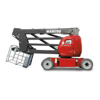
Manitou AETJC 150 Repair Manual (286 pages)
Brand:
Manitou
| Category:
Boom Lifts
| Size: 41 MB
Table of Contents
General Characteristics and Safety
10
Table of Contents
10
General Instructions and Safety Notice
11
Introduction
11
Servicing Position
11
Explanation of Symbols
12
Servicing Rules
13
General Characteristics and Specifications
16
Characteristics
16
Lubricants and Fuel
16
Dimensions
17
Dimensions 120Aetjl
17
Dimensions 150Aetjc - Aetj 43 - Aetjc 43 3D
19
Dimensions 150Aetjl
21
Dimensions 170Aetjl - 49 Aetjc
23
Location of Name and Identification Plate
25
Access Platform Manufacturer's Plate
25
Location of Manufacturer's Plate
25
Aetj
25
General Control and Adjustment
26
Standard Tightening Torques
26
Metric - Imperial Unit Conversion
27
Hydraulic
36
Hydraulic Schematic Diagrams
38
679449 - Hydraulic Diagram
38
685268 - Hydraulic Diagram
42
Hydraulic Components Location
46
Hydraulic Components of the Chassis - Location
46
Hydraulic Components of the Turret - Location
47
Hydraulic Components of the Jib - Location
48
Hydraulic Control and Adjustment
50
Main Circuit - Pressure Setting
50
Steering, Basket/Turret Rotation Circuit - Pressure Setting
50
Brake Release Circuit - Pressure Setting
51
Pressure Switch Adjustment
51
Telescopic Circuit - Pressure Setting
52
Pressure Reducer Setting
52
Compensation/Tilting Circuit - Pressure Setting
53
Decompression of the Circuit
53
Valve a Adjustment
53
Valve B Adjustment
54
Compensation/Tilting Circuit - Problem Solving
55
Test Procedure
55
Analysis of Results
56
Turret Rotation Motor - Removal
57
Electric Pump - Removal
58
Reducing Gears/Wheel Brakes - Removal
59
Distributor - Removal
60
Distributor - Details
62
Cylinders - Removal
63
Steering Cylinder - Removal
63
Refit
63
Arm 1/2 Lifting Cylinder - Removal
64
Arm 3 Lifting Cylinder - Removal
65
Telescopic Cylinder - Removal
66
Compensation/Tilting Cylinder Removal
67
Jib Cylinder - Removal
69
Basket Rotation Cylinder - Removal
70
Rotation Cylinder (3D - Jib) - Removal
71
Electricity
74
Electrical Schematic Diagrams
76
Schematic Diagram - Power Part
78
Schematic Diagram - Base Control Part
79
Schematic Diagram - Basket Control Part
80
Schematic Diagram - Safety Control Unit Part
81
Schematic Diagram - Power Part
82
Schematic Diagram - Basket Control Part
83
Schematic Diagram - Safety Control Unit Part
84
Electrical Components Location
86
Electrical Control Components - Location
86
Electrical Power Components - Location
87
Wiring Based on Schematic Diagram 676423
88
Location of Wiring Harnesses on the Access Platform
88
Basket Control Panel Harness
89
Overload Sensors Harness
92
Upper Bus-Can Extension Harness
93
Lower Bus-Can Extension Harness
95
Upper Bus-Can Control Panel Output Harness
96
Base Box Harness
97
Variable Speed Controller Harness
99
Electrovalve Harness
100
Miscellaneous Harness
101
Electrical Control and Adjustment
104
Zivan Battery Charger
104
Zivan Battery Charger Removal
104
Zivan Battery Charger Description
105
External View
105
Internal View
105
Zivan Battery Charger Connections
106
Ies Battery Charger
109
Ies Battery Charger Removal
109
Ies Battery Charger Description
110
External View
110
Ies Battery Charger Connections
110
Ies Battery Charger Connections Load Curves
111
Ies Battery Charger - Indicator
111
Electronic Modules - Control and Settings
112
Electronic Control Units - Removal
112
Electronic Control Units Description and Wiring
113
Electronic Modules - Diagnostics and Settings
117
Variable Speed Controllers - Control and Settings
118
Variable Speed Controllers - Description
118
Variable Speed Controllers - Wiring
119
Variable Speed Controllers - Diagnostic and Adjustment Tools
121
Battery Charge Indicator/Hour Meter
122
Variable Speed Controllers - Use of Calibrator
123
Safety Components - Control and Settings
129
Switches - Location
129
Tilt Sensor - Settings
129
Arm down Sensors - Settings
130
Brake Release Circuit - Checking
131
Overload Sensors - Settings
132
Multimeter Test
135
Manipulator - Operation and Settings
136
Manipulator - Tests Using Calibrator
136
Manipulator - Test with a Voltmeter
137
Electricity Removals - Refitting
139
Variable Speed Controllers - Removal
139
Batteries - Removal
140
Electrical Harnesses - Removal
141
Troubleshooting - Electrical
142
Variable Speed Controllers - Faults and Fixes
142
Zivan Battery Charger - Error Signals
146
Ies Battery Charger
146
Specific Tooling - Electricity
147
Calibrator
147
Description
147
General Characteristics and Safety
148
General Instructions and Safety Notice
149
Introduction
149
Servicing Position
149
Explanation of Symbols
150
Servicing Rules
151
General Characteristics and Specifications
154
Characteristics
154
Lubricants and Fuel
154
Dimensions
155
Dimensions 120Aetjl
155
Dimensions 150Aetjc - Aetj 43 - Aetjc 43 3D
157
Dimensions 150Aetjl
159
Dimensions 170Aetjl - 49 Aetjc
161
Location of Name and Identification Plate
163
Access Platform Manufacturer's Plate
163
Location of Manufacturer's Plate
163
Aetj
163
General Control and Adjustment
164
Standard Tightening Torques
164
Metric - Imperial Unit Conversion
165
Hydraulic
174
Hydraulic Schematic Diagrams
176
679449 - Hydraulic Diagram
176
685268 - Hydraulic Diagram
180
Hydraulic Components Location
184
Hydraulic Components of the Chassis - Location
184
Hydraulic Components of the Turret - Location
185
Hydraulic Components of the Jib - Location
186
Hydraulic Control and Adjustment
188
Main Circuit - Pressure Setting
188
Steering, Basket/Turret Rotation Circuit - Pressure Setting
188
Brake Release Circuit - Pressure Setting
189
Pressure Switch Adjustment
189
Telescopic Circuit - Pressure Setting
190
Pressure Reducer Setting
190
Compensation/Tilting Circuit - Pressure Setting
191
Decompression of the Circuit
191
Valve a Adjustment
191
Valve B Adjustment
192
Compensation/Tilting Circuit - Problem Solving
193
Test Procedure
193
Analysis of Results
194
Turret Rotation Motor - Removal
195
Electric Pump - Removal
196
Reducing Gears/Wheel Brakes - Removal
197
Distributor - Removal
198
Distributor - Details
200
Cylinders - Removal
201
Steering Cylinder - Removal
201
Refit
201
Arm 1/2 Lifting Cylinder - Removal
202
Arm 3 Lifting Cylinder - Removal
203
Telescopic Cylinder - Removal
204
Compensation/Tilting Cylinder Removal
205
Jib Cylinder - Removal
207
Basket Rotation Cylinder - Removal
208
Rotation Cylinder (3D - Jib) - Removal
209
Electricity
212
Electrical Schematic Diagrams
214
Schematic Diagram - Power Part
216
Schematic Diagram - Base Control Part
217
Schematic Diagram - Basket Control Part
218
Schematic Diagram - Safety Control Unit Part
219
Schematic Diagram - Safety Control Unit Part
223
Electrical Components Location
224
Electrical Control Components - Location
224
Electrical Power Components - Location
225
Wiring Based on Schematic Diagram 676423
226
Location of Wiring Harnesses on the Access Platform
226
Basket Control Panel Harness
227
Overload Sensors Harness
230
Upper Bus-Can Extension Harness
231
Lower Bus-Can Extension Harness
233
Upper Bus-Can Control Panel Output Harness
234
Base Box Harness
235
Variable Speed Controller Harness
237
Electrovalve Harness
238
Miscellaneous Harness
239
Electrical Control and Adjustment
242
Zivan Battery Charger
242
Zivan Battery Charger Removal
242
Zivan Battery Charger Description
243
External View
243
Internal View
243
Zivan Battery Charger Connections
244
Zivan Battery Charger Connections Load Curves
245
Ies Battery Charger
247
Ies Battery Charger Removal
247
Ies Battery Charger Description
248
External View
248
Ies Battery Charger Connections
248
Ies Battery Charger Connections Load Curves
249
Ies Battery Charger - Indicator
249
Electronic Modules - Control and Settings
250
Electronic Control Units - Removal
250
Electronic Control Units Description and Wiring
251
Electronic Modules - Diagnostics and Settings
255
Variable Speed Controllers - Control and Settings
256
Variable Speed Controllers - Description
256
Variable Speed Controllers - Wiring
257
Variable Speed Controllers - Diagnostic and Adjustment Tools
259
Battery Charge Indicator/Hour Meter
260
Variable Speed Controllers - Use of Calibrator
261
Safety Components - Control and Settings
267
Switches - Location
267
Tilt Sensor - Settings
267
Arm down Sensors - Settings
268
Brake Release Circuit - Checking
269
Overload Sensors - Settings
270
Manipulator - Operation and Settings
274
Manipulator - Tests Using Calibrator
274
Manipulator - Test with a Voltmeter
275
Electricity Removals - Refitting
277
Variable Speed Controllers - Removal
277
Batteries - Removal
278
Electrical Harnesses - Removal
279
Troubleshooting - Electrical
280
Variable Speed Controllers - Faults and Fixes
280
Zivan Battery Charger - Error Signals
284
Ies Battery Charger
284
Specific Tooling - Electricity
285
Calibrator
285
Description
285
Advertisement
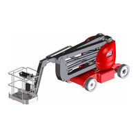
Manitou AETJC 150 Operator's Manual (134 pages)
Brand:
Manitou
| Category:
Lifting Systems
| Size: 11 MB
Table of Contents
Table of Contents
51
Emergency Stop Button
54
Ignition Switch
54
Activation Button
54
Basket Rotation Switch
55
Jib Switch
55
Jib Rotation Switch (Only for 150 Aetj 3D (150 Aetjc 3D))
55
Telescopic Arm Switch
55
Main Arm Switch
55
Multi-Function Display
56
Basket Tilt Switch
56
Turntable Rotation Switch
56
Secondary Arm Switch
56
Overload Alarm Light
57
Maintenance/Fault Alarm Indicator Lamp
57
Battery Charger Status Indicator Lamp
57
Battery Cut-Off
57
Orange Flashing Light (Option)
58
Tilt Sensor
58
Horn
58
Flashing Light Sps (Option)
58
Emergency Stop Button
59
Horn Button
59
Control Handle
60
Rotation Mode Selection Switch
60
Basket Tilting Activation Switch and Indicator Lamp
61
Jib Activation Switch and Light
61
Telescopic Arm Activation Switch and Indicator Lamp
62
Main Arm Activation Switch and Indicator Lamp
62
Secondary Arm Activation Switch and Indicator Lamp
62
Operation Activation Switch and Indicator Lamp
63
Cover (Option)
64
Safety Cable Sps (Option)
64
Safety Edge Sps (Option)
64
Reset Button Sps (Option)
64
Audible Alarm
64
Overload/Fault Alarm Indicator Lamp
64
Tilt Alarm Light
64
Daily and Weekly Maintenance T T
92
Check
100
General Inspection
100
Hydraulic Oil Level
100
CHECK Battery Charge Level
101
CHECK Battery Fluid Level
101
CHECK Platform Controls
102
CHECK Secondary Protection System SPS - First Version "Safemansystem" (OPTION)
108
CHECK Secondary Protection System SPS - Second Version (OPTION)
109
Also Perform the Daily Maintenance
110
Check
110
Weekly Maintenance
110
Wheel Nut Tightening
110
Battery Electrolyte Specific Gravity
111
Check
111
Front Steering Pivots and Steering Cylinder Ring
111
Grease
111
Battery Trays
112
Bleed
112
RESET Maintenance Warning
116
CHECK Telescope Setting
119
Check
120
Counterweight Fixing Screw Tightening
120
Tightening of the Battery Fixing Screws
120
Tightening of the Fixing Screws on the Turntable Motor
120
Check
121
CHECK Overload Alarm
121
Brakes
122
Check
123
CHECK Turntable Motor Oil Level
123
Hydraulic Hoses
123
GREASE Crown Gear Bearings
124
LUBRICATE Telescope
124
Check
126
CHECK Tightening of the Fixing Screws for the Crown Gear
126
Replace
127
Turntable Motor Oil
127
Wheel Reduction Gear Oil
127
Clean
128
REPLACE Hydraulic Oil
128
REPLACE Hydraulic Return Filter Cartridge
128
Suction Strainer
128
CHECK Condition of Cylinders
129
Clearance of Crown Gear
129
Condition of Electric Wiring
129
Consult Your Dealer
129
Maintenance Warning
129
Reset
129
Batteries
130
Occasional Maintenance
130
Replace
130
Wheels
130
Fuses
131
Replace
131
Lift
132
Occasional Operation
132
Platform
132
Platform
134
Transport
134
Advertisement
Related Products
Manitou AETJL 120
Manitou AETJL 170
Manitou AETJ 43
Manitou AETJ 49
Manitou Aurora
Manitou Aurora LE
Manitou Aurora Angler
Manitou A Series
Manitou MT 1440 A 100D ST5 S1
Manitou 120 AETJ COMPACT
Manitou Categories
Forklifts
Bicycle Accessories
Lifting Systems
Boom Lifts
Construction Equipment
More Manitou Manuals
Login
Sign In
OR
Sign in with Facebook
Sign in with Google
Upload manual
Upload from disk
Upload from URL