
Related Manuals for Tenma 72-7800


Summary of Contents for Tenma 72-7800
- Page 1 Digital Clamp Meter User Manual Part Number: 72-7800 Newark.com/exclusive-brands Farnell.com/exclusive-brands Element14.com/exclusive-brands Page <1> 25/03/22 V1.0...
-
Page 2: Table Of Contents
Table of Contents 1. Overview ............3 2. -
Page 3: Overview
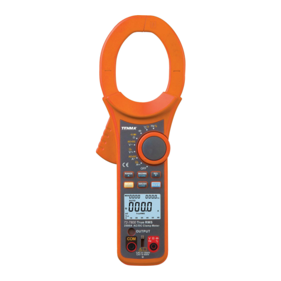
1. Overview 72-7800 is a portable true RMS 5-5/6 bit (6000 Counts), auto range clamp ammeter with analog simulation bar graph. The clamp ammeter featuring full-function on screen display, full-range overload protection and unique design makes this a highly featured clamp ammeter with incredible performance. -
Page 4: External Structure
DC (Direct Current) Buzzing on-off Diode Low battery AC or DC (Alternating current or direct current) Danger. High Voltage. Comply with EU standards 5. External Structure 1. Clamp ammeter body: Designed to safely protect operator from electric shock during proper use. 2. -
Page 5: Key Function
10. DC DC measurement 11. True RMS TrueRMS measurement 12. +System Digit and Simulation Bar Measurement of reading value LPF measurement 14. INRUSH INRUSH current measurement Buzzing on-off measurement Diode measurement 17. Zero AC current gear ZERO 18. Max, Min Maximum and minimum value measurement Relative measurement 20. -
Page 6: Inrush/Load
to exit this mode. While in DC current measurement mode, you can clear the mode with a short press, and display will show “ZERO”. While in the data recording mode, you can do a long press to quit the continuous data recording mode. While in the data recall mode, you can review the data downward by pressing this key. -
Page 7: Resistance Measurement
Note: Beware of potential electric shock when measuring high voltage. After completing all measurement operations, disconnect test leads from the measured circuit. When the measured voltage is greater than the 30V AC, the meter LCD displays a high voltage warning symbol “ ” If the measured voltage is greater than the 1000V limit, the meter will intermittently buzz while the high voltage warning “... -
Page 8: Circuit On-Off Measurement
4. Circuit on-off measurement 1) Insert red test leads in “Ω” jack and black test leads in “COM” jack. 2) P ush the function range switch to the measurement Position “Ω ”, press SELECT to select circuit on-off measurement and connect test leads in parallel with the two terminals of measured circuit. When the measured resistance between two terminals <30Ω, the circuit should be deemed conductive, buzzer will sound continuously. When resistance is ≥30Ω, the buzzer will not sound. 3) Directly read the measured resistance value loaded by the circuit from display. Note: When checking a circuit, prior to measurement, be certain to power off all power sources and discharge any inline capacitors. ... -
Page 9: Capacitance Measurement
Note: “OL” will be displayed when the measured diode is open-circuit or polarity is inversely connected. Before diode measurement, make sure all circuits are powered off and discharge any capacitors for best measurement ac- curacy. The test open-circuit voltage of diode is approximately 3.5V. Do not input voltage higher than DC 42V or AC 30V, which may cause personal injury. After completing all measurement operations, disconnect the test leads from the measured circuit. -
Page 10: Frequency/Duty Ratio Measurement
7. Frequency/duty ratio measurement 1) Insert red test leads in “Hz” jack and black test leads in“COM” jack. 2) Select the “ ” position on the function switch, and press the red key to select the “Hz” frequency measurement function. Connect the rest leads in parallel with signal to be measured. 3) Directly read out the measured frequency value from display. -
Page 11: Dc Current Measurement
9. DC current measurement 1) Select the “ ” on the function switch. If the display does not read zero, press REL to reset the voltage measurement to zero. You may need to repeat this after each current measurement. 2) Squeeze clamp trigger to open the clamp head and place around single conductor to be measured. Slowly release the clamp trigger to make certain that the head is completely closed. -
Page 12: Current Signal Output Function
11. Current signal output function The 72-7800 clamp meter features a current output signal function. The signal converts measured current into voltage at a ratio of 1A/amV readable by other meters and pieces of test equipment. For example, this allows you to observe current as a waveform on an oscilloscope, or collect data with PC enabled equipment. -
Page 13: Technical Specifications
9. Technical Specifications 1. General specification • Liquid crystal display: 3-5/6 digit LCD, maximum display 6000 count. • Polarity display: auto positive and negative polarity display. • Overload display: “OL” or “-OL” . • Low voltage display: “ ” indicates that battery voltage is lower than working voltage. • ... - Page 14 Range Resolution Accuracy: ±(% reading + count) 1000V ±(1.2%+3) ±(2.5%+3) Input impedance: about 10MΩ Overload protection: 1000V Display: true RMS, applicable to 10%-100% of the range. (3) Voltage AC+DC Range Resolution Accuracy: ±(% reading +count) 0.001V 40Hz~400Hz 400Hz~1kHz 0.01V ±(2%+20) ±(4%+20) 600V 0.1V 1000V ±(2.5%+20) ±(5%+20 ) Input impedance: about 10MΩ Overload protection: 1000V Display: true RMS, applicable to 10%~100% of the range. (4) DC current A Range Resolution...
- Page 15 (8) Continuity test Range Resolution Remark Open-circuit voltage is about -3.5V; Sound continuity is 0.1Ω set as <30Ω, buzzer continuously sounds. Short circuit is set as ≥30Ω, buzzer will not sound. Overload protection: 1000V (9) Diode Range Resolution Remark Open circuit voltage is about 3.5V, able to measure the PN junction 0.001V <3V forward voltage drop value. The normal voltage value of silicon PN junction is about 0.5~0.8V.
-
Page 16: Maintenance And Upkeep
Liability for loss or damage resulting from any reliance on the Information or use of it (including liability resulting from negligence or where the Group was aware of the possibility of such loss or damage arising) is excluded. This will not operate to limit or restrict the Group’s liability for death or personal injury resulting from its negligence. TENMA is the registered trademark of Premier Farnell Limited 2019. Newark.com/exclusive-brands Farnell.com/exclusive-brands...
Need help?
Do you have a question about the 72-7800 and is the answer not in the manual?
Questions and answers