Table of Contents
Advertisement
Quick Links
Advertisement
Table of Contents

Related Manuals for KTM 1290 Super Duke R US 2020


Summary of Contents for KTM 1290 Super Duke R US 2020
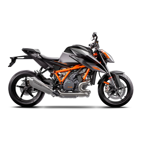
- Page 1 OWNER'S MANUAL 2020 1290 Super Duke R Art. no. 3214111en...
- Page 3 KTM accepts no liability for delivery options, deviations from fig- ures and descriptions, misprints, and other errors. The models portrayed partly contain special equipment that does not belong to the regular scope of supply.
- Page 4 Reproduction, even in part, as well as copying of all kinds, is permitted only with the express written permission of the copyright owner. ISO 9001(12 100 6061) KTM applies quality assurance processes that lead to the highest possible product quality as defined in the ISO 9001 international quality management standard. Issued by: TÜV Management Service KTM Sportmotorcycle GmbH Stallhofnerstraße 3...
-
Page 5: Table Of Contents
TABLE OF CONTENTS Fuel, auxiliary substances ....26 TABLE OF CONTENTS MEANS OF REPRESENTATION ....10 Spare parts, accessories ....26 Symbols used ........10 Service ........... 27 Formats used........11 Figures ........... 27 SAFETY ADVICE.......... 12 Customer service......27 Use definition –... - Page 6 TABLE OF CONTENTS Menu buttons ........39 Activation and test ......61 Turn signal switch......40 Day-night mode ....... 63 Horn button........41 Warnings......... 64 Cruise control buttons ...... 41 Ice warning ........65 6.10 +RES/-SET button......44 Indicator lamps........ 66 6.11 Combination switch, right ....
- Page 7 TABLE OF CONTENTS 7.28 Menu..........89 7.28.25 Quickshifter + (optional)..... 115 7.28.1 KTM MY RIDE (optional) ....89 7.28.26 Settings ........115 7.28.2 Audio (optional) ......90 7.28.27 C1 and C2 buttons..... 116 7.28.3 Navigation (optional) ....92 7.28.28 Bluetooth (optional) ....117 7.28.4...
- Page 8 TABLE OF CONTENTS ERGONOMICS .......... 141 10.2 Starting the vehicle ......161 10.3 Launch Control (optional) ....164 Handlebar position......141 10.4 Starting off........164 Adjusting the handlebar 10.5 Starting off with launch control position ........141 (optional) ........165 Adjusting the basic position of the 10.6 Quickshifter+ (optional) ....
- Page 9 TABLE OF CONTENTS 12.5 Bleeding the fork legs..... 192 13.6 Removing the motorcycle from the work stand (inserted) ....204 12.6 Compression damping of the shock absorber........193 13.7 Cleaning the dust boots of the fork 12.7 Adjusting the spring preload of the legs ...........
- Page 10 TABLE OF CONTENTS 14.4 Adding front brake fluid ....238 16.7 Changing the fuses in the fuse box ..........272 14.5 Checking the front brake linings ..241 14.6 Checking the rear brake fluid 16.8 Changing the turn signal bulb ..275 level ..........
- Page 11 TABLE OF CONTENTS 19.2 Changing the engine oil and oil 23.8 Shock absorber ......325 filter, cleaning the oil screens ..291 23.9 Chassis tightening torques ....326 19.3 Adding engine oil ......298 24 DECLARATIONS OF CONFORMITY ..... 333 20 CLEANING, CARE ........
-
Page 12: Means Of Representation
All work marked with this symbol requires specialist knowledge and technical understanding. In the interest of your own safety, have these jobs performed by an authorized KTM workshop! Your motorcycle will be optimally cared for there by specially trained experts using the auxiliary tools required. -
Page 13: Formats Used
MEANS OF REPRESENTATION 1 Indicates a voltage measurement. Indicates a current measurement. Indicates the end of an activity, including potential rework. Formats used The typographical formats used in this document are explained below. Proprietary name Indicates a proprietary name. Name ®... -
Page 14: Safety Advice
2 SAFETY ADVICE Use definition – intended use The vehicle is designed and constructed to withstand the usual demands of regular traffic and use on race courses. This vehicle is not suitable for offroad use. Info This vehicle is only authorized for operation on public roads in its homologated version. Misuse The vehicle must only be used as intended. -
Page 15: Degrees Of Risk And Symbols
SAFETY ADVICE 2 Info Various information and warning labels are attached in prominent locations on the product described. Do not remove any information or warning labels. If they are missing, you or others may not recognize dangers and may therefore be injured. Degrees of risk and symbols Danger Identifies a danger that will immediately and invariably lead to fatal or serious permanent injury if the... -
Page 16: Overview Of Labels
2 SAFETY ADVICE Overview of labels S04094-10... - Page 17 SAFETY ADVICE 2 Information on noise emissions Type label for Canada Information on chain tension Information on suspension setting Information on preparations for use Type label for USA Information on emissions control S04095-01 Information on noise emissions...
- Page 18 2 SAFETY ADVICE S04096-01 Type label for Canada Information on chain tension L01472-01...
- Page 19 SAFETY ADVICE 2 Information on suspension setting S04099-01 Information on preparations for use F00491-01...
- Page 20 2 SAFETY ADVICE S04097-01 Type label for USA S04098-01 Information on emissions control...
-
Page 21: Reporting Safety Defects
DC 20590. You can also obtain other information about motor vehicle safety from the Hotline. Noise emission warranty KTM warrants that this exhaust system, at the time of sale, meets all applicable U.S. EPA Federal noise stan- dards. This manufacturer warranty extends to the first person who buys this exhaust system for purposes other than resale, and to all subsequent buyers. -
Page 22: Operating Noise Warning
As the owner of the motorcycle, you are responsible for the required maintenance specified in the Owner's Man- ual. Please note that KTM is entitled to reject warranty claims if your motorcycle or a part fails due to misuse, neg- ligence, an accident, participation in racing or similar events, improper maintenance or unauthorized modifica- tions. -
Page 23: Consumer Rights
California Air Resources Board, 1001 "I" Street, Sacramento, CA 95814, USA 2.10 Consumer rights Warranty claims must be submitted to an authorized KTM workshop. If you are not satisfied, please contact: KTM North America, Inc., Customer Support, 1119 Milan Ave., Amherst, OH 44001, USA Phone: (440) 985-3553 www.ktmusa.com... -
Page 24: Safe Operation
2 SAFETY ADVICE 1 Removal or puncturing of the main silencers, baffles, header pipes or any other components which conduct exhaust gases. 2 Removal or puncturing of parts of the intake system. 3 Lack of proper maintenance. 4 Replacing moving parts of the vehicle, or parts of the exhaust system or intake system, with parts other than those specified by the manufacturer. -
Page 25: Protective Clothing
Wear appropriate protective clothing such as helmet, boots, gloves as well as trousers and a jacket with protectors on all rides. – Always wear protective clothing that is in good condition and meets the legal regulations. In the interest of your own safety, KTM recommends that you only operate the vehicle while wearing protective clothing. -
Page 26: Work Rules
Because motorcycles are not subject to the EU regulations governing the disposal of used vehicles, there are no legal regulations that pertain to the disposal of an end-of-life motorcycle. Your authorized KTM dealer will be glad to advise you. -
Page 27: Owner's Manual
The Owner's Manual is an important component of the vehicle and must be handed over to the new owner if the vehicle is sold. The Owner's Manual is also available for download from your authorized KTM dealer and on the KTM website. International KTM Website: http://www.ktm.com... -
Page 28: Important Notes
Manufacturer and implied warranty The work prescribed in the service schedule must only be carried out in an authorized KTM workshop and con- firmed in the KTM Dealer.net, as otherwise all warranty claims will be void. Damage or secondary damage caused by tampering with and/or conversions on the vehicle are not covered by the manufacturer warranty. -
Page 29: Service
Customer service Your authorized KTM dealer will be happy to answer any questions you may have on your vehicle and KTM. A list of authorized KTM dealers can be found on the KTM website. International KTM Website: http://www.ktm.com... -
Page 30: View Of Vehicle
4 VIEW OF VEHICLE View of vehicle, front left (example) S03093-10... - Page 31 VIEW OF VEHICLE 4 Clutch lever ( p. 36) Supporting strap ( p. 55) Tool set ( p. 54) Seat lock ( p. 54) Passenger foot pegs ( p. 55) Rider footrests Shift lever ( p. 56) Side stand ( p.
-
Page 32: View Of Vehicle, Rear Right (Example)
4 VIEW OF VEHICLE View of vehicle, rear right (example) S03094-10... - Page 33 VIEW OF VEHICLE 4 Fuel tank filler cap Combination switch, left side ( p. 37) Emergency OFF switch/electric starter button ( p. 46) RACE-ON button ( p. 47) Hazard warning flasher switch ( p. 45) Throttle grip ( p. 37) Hand brake lever ( p.
-
Page 34: Serial Numbers
5 SERIAL NUMBERS Vehicle identification number The vehicle identification number is stamped on the right side of the steering head. The vehicle identification number is also shown on the type label. 402324-10 Type label The type label for the USA is located on the steering head. -
Page 35: Key Number
SERIAL NUMBERS 5 The type label for Canada is located on the frame on the left. 402293-10 Key number The key number Code number can be found on the KEYCODECARD. Info You need the key number to order a spare key. Keep the KEYCODECARD in a safe place. -
Page 36: Engine Number
5 SERIAL NUMBERS Engine number The engine number is stamped on the right side of the engine. 402296-10 Fork part number The fork part number is stamped on the inside of the axle clamp. 402295-10... -
Page 37: Shock Absorber Article Number
SERIAL NUMBERS 5 Shock absorber article number The shock absorber article number is stamped on the top of the shock absorber above the adjusting ring towards the engine side. 402798-10 Steering damper article number Steering damper item number is embossed on the underside of the steering damper. -
Page 38: Controls
6 CONTROLS Clutch lever Clutch lever is fitted on the handlebar on the left. The clutch is activated hydraulically and adjusts itself automati- cally. S03879-10 Hand brake lever The hand brake lever is fitted on the right side of the handle- bar. -
Page 39: Throttle Grip
CONTROLS 6 Throttle grip The throttle grip is fitted on the right side of the handlebar. S03880-11 Combination switch, left side The left combination switch is fitted on the left side of the handle- bar. -
Page 40: Light Switch
6 CONTROLS Overview of the left combination switch Light switch ( p. 38) Cruise control buttons ( p. 41) Menu buttons ( p. 39) Turn signal switch ( p. 40) Horn button ( p. 41) +RES/-SET button ( p. 44) S03881-10 Light switch The light switch... -
Page 41: Menu Buttons
CONTROLS 6 Headlight flasher – Light switch in position . The headlight flasher is operated in this position. The light switch returns automatically to the position after use. Menu buttons The menu buttons are fitted in the middle of the left combination switch. -
Page 42: Turn Signal Switch
6 CONTROLS Turn signal switch Turn signal switch is fitted on the combination switch on the left. Possible states Turn signal off – Turn signal switch pushed toward the switch housing. Left turn signal, on – Turn signal switch pressed to the left. -
Page 43: Horn Button
CONTROLS 6 Horn button Horn button is fitted on the left side of the handlebar. Possible states • The horn button is in the basic position is pressed – The horn is operated in this • The horn button position. S03881-13 Cruise control buttons The cruise control buttons... - Page 44 6 CONTROLS Button ‑SET is pressed. – The cruise control system function • is activated and the current speed is maintained. Every sub- sequent brief press reduces the target speed by 1 km/h or 1 mph. Button ‑SET is pressed and held. – The target speed •...
- Page 45 CONTROLS 6 – Control of the motorcycle traction control (MTC) – Slip at the rear wheel or lifting front wheel – A fault occurring, which impairs the cruise control system function – Exceeding the target speed for more than 30 seconds when overtaking Warning Danger of accidents The cruise control system function is...
-
Page 46: Res/-Set Button
6 CONTROLS When motorcycle traction control (MTC) is switched off, the cruise control system function is also switched off. The cruise control system function cannot be activated during rapid acceleration. The cruise control system function can only be activated in third, fourth, fifth and sixth-gear. -
Page 47: Hazard Warning Flasher Switch
CONTROLS 6 Overview of the right combination switch C1 and C2 switch ( p. 48) Hazard warning flasher switch ( p. 45) RACE-ON button ( p. 47) Emergency OFF switch/electric starter button ( p. 46) S03883-11 6.12 Hazard warning flasher switch The hazard warning flasher switch is fitted on the right side of the combination switch. -
Page 48: Emergency Off Switch/Electric Starter Button
6 CONTROLS Possible states Hazard warning flasher on – All four turn signals and the green turn signal indicator lights in the combina- tion instrument flash. 6.13 Emergency OFF switch/electric starter button The emergency OFF switch/electric starter button is fitted on the right side of the combination switch. -
Page 49: Race-On Button
CONTROLS 6 6.14 RACE-ON button The RACE-ON button is fitted on the right side of the combi- nation switch. Info The RACE-ON button performs the ignition lock function on this vehicle. The steering can only be locked if the handlebar is turned to the left. -
Page 50: C1 And C2 Switch
6 CONTROLS 6.15 C1 and C2 switch The C1 and C2 switch is fitted on the right of the combination switch. Info The C1 and C2 switch enables quick access to various menus. The C1 and C2 switch can be freely configured. S03884-10 6.16 Steering lock (antenna) -
Page 51: Immobilizer
CONTROLS 6 Info Store the ignition key safely again as soon as the engine has been started. Possible states Ignition off, steering locked – In this operating mode, the • ignition circuit is interrupted and the steering locked. Ignition off, steering unlocked – In this operating mode, the •... -
Page 52: Race-On Key
The ignition keys contain electronic components. Always maintain a distance of several centimeters to other devices with electronic components. A lost ignition key must be deactivated by an authorized KTM workshop to prevent unauthorized persons from operating the vehi- cle. -
Page 53: Opening Fuel Tank Filler Cap
CONTROLS 6 6.19 Opening fuel tank filler cap Danger Fire hazard Fuel is highly flammable. The fuel in the fuel tank expands when warm and can escape if overfilled. – Do not refuel the vehicle in the vicinity of open flames or lit cigarettes. –... - Page 54 6 CONTROLS Note Environmental hazard Improper handling of fuel is a danger to the environment. – Do not allow fuel to enter the groundwater, the soil, or the sewage system. Condition The motorcycle is stationary. The engine is switched off. The ignition has been switched on or off for less than 1 minute. –...
-
Page 55: Closing The Fuel Tank Filler Cap
CONTROLS 6 6.20 Closing the fuel tank filler cap Warning Fire hazard Fuel is highly flammable, toxic and a health hazard. – Check that the fuel tank filler cap is locked cor- rectly after closing. – Change your clothing if fuel spills on them. –... -
Page 56: Seat Lock
6 CONTROLS 6.21 Seat lock Seat lock is located on the left side of the vehicle under the seat. It can be unlocked using the RACE-ON key or the black ignition key. S03887-10 6.22 Tool set The tool set is located under the passenger seat. S03888-10... -
Page 57: Supporting Strap
CONTROLS 6 6.23 Supporting strap Supporting strap is attached underneath the passenger seat. Info If the supporting strap is not needed, it can be stowed underneath the pillion bench. The supporting strap is provided for the passenger to hold on to. S03889-10 6.24 Passenger foot pegs... -
Page 58: Shift Lever
6 CONTROLS 6.25 Shift lever The shift lever is fitted on the left side of the engine. 402299-10 The gear positions can be seen in the figure. The idle position is between first and second gears. 402299-11... -
Page 59: Foot Brake Lever
CONTROLS 6 6.26 Foot brake lever Foot brake lever is located in front of the right footrest. The rear brake is engaged with the foot brake lever. 402301-10 6.27 Side stand Side stand is located on the left of the vehicle. The side stand is used for parking the motorcycle. - Page 60 6 CONTROLS Side stand folded in – This position is mandatory when riding • the motorcycle. The safety starting system is inactive.
- Page 61 COMBINATION INSTRUMENT 7...
-
Page 62: Combination Instrument
7 COMBINATION INSTRUMENT Combination instrument S03758-10... -
Page 63: Activation And Test
COMBINATION INSTRUMENT 7 The combination instrument is attached in front of the handlebar. The combination instrument is divided into two function areas. indicator lamps ( p. 66) Display Activation and test Activation The combination instrument is activated when the ignition is switched on. - Page 64 (taking care not to endanger yourself or other road users in the process) and contact an authorized KTM workshop. The oil pressure warning lamp always lights up as long as the engine is not running. If the engine is running and the...
-
Page 65: Day-Night Mode
COMBINATION INSTRUMENT 7 Day-night mode Day mode is shown in a bright color. S03748-01 Night mode is shown in a dark color. Info The ambient light sensor in the combination instrument measures the brightness of the environment and automat- ically switches the display to day or night mode. The dis- play is brightened, darkened or switched to the other mode depending on the brightness measured by the ambient light sensor. -
Page 66: Warnings
7 COMBINATION INSTRUMENT Warnings Warnings appear on the bottom edge of the display; these are marked yellow or red depending on their relevance. Yellow warnings indicate errors or information which require prompt intervention or an adjustment to the riding style. Red warnings indicate errors or information which require immedi- ate intervention. -
Page 67: Ice Warning
COMBINATION INSTRUMENT 7 Ice warning The ice warning goes on when there is an increased risk of ice on the roads. The ice warning is shown in area of the display. The ice warning appears on the display when the ambient tem- perature drops below the specified value. -
Page 68: Indicator Lamps
7 COMBINATION INSTRUMENT Indicator lamps S03764-01... - Page 69 (taking care not to endanger yourself or other road users in the process) and contact an authorized KTM workshop. The oil pressure warning lamp always lights up as long as the engine is not running. If the engine is run- ning and the oil pressure warning lamp lights up, stop immediately (taking care not to endanger yourself or other road users in the process) and switch off the engine.
- Page 70 287) is not active, is currently intervening or a Launch Control Start is being executed. The TC indicator lamp also lights up if an error is detected. Contact an authorized KTM workshop. The TC indicator lamp flashes if the motorcycle traction control actively engages.
- Page 71 COMBINATION INSTRUMENT 7...
-
Page 72: Display
7 COMBINATION INSTRUMENT Display S03766-10... - Page 73 COMBINATION INSTRUMENT 7 Info The figure shows the start screen of the combination instrument. If the menu is opened, the speed is still displayed. Tachometer Shift warning light ( p. 80) The shift warning light is integrated in the tachometer display. Speed Unit for the speedometer Fuel level display (...
-
Page 74: Track Display (Optional)
7 COMBINATION INSTRUMENT TRACK Display (optional) S03768-10... - Page 75 COMBINATION INSTRUMENT 7 Info The figure shows the start screen of the combination instrument in active drive mode TRACK (optional). If the menu is opened, the speed is still displayed. Anti wheelie mode (optional) ( p. 288) Launch Control (optional) ( p.
-
Page 76: Performance Layout (Optional)
7 COMBINATION INSTRUMENT Performance layout (optional) S03769-10... - Page 77 The figure shows the start screen of the combination instrument in active drive mode TRACK (optional) in the per- formance layout. In the performance layout, you can use KTM MY RIDE in TRACK mode (optional). If the menu is opened, the speed is still displayed.
-
Page 78: Small Widget
7 COMBINATION INSTRUMENT 7.10 Small widget S03785-01... - Page 79 COMBINATION INSTRUMENT 7 The figure shows the start screen of the combination instrument with the small widget opened. Information can be accessed in the small widget.
-
Page 80: Large Widget
7 COMBINATION INSTRUMENT 7.11 Large widget S03786-01... -
Page 81: Odometer
COMBINATION INSTRUMENT 7 The figure shows the start screen of the combination instrument with the large widget opened. Information can be accessed and configured in the large widget. 7.12 Odometer The odometer can be displayed in the FAVORITES widget as Trip 1. To do this, the information must be configured in the widget. -
Page 82: Engine Speed
7 COMBINATION INSTRUMENT 7.13 Engine speed The engine speed is shown in area of the display. The engine speed is measured in revolutions per minute. S03750-01 7.14 Shift warning light The shift warning light is integrated in the tachometer display. In the Settings menu under Shift Light, the engine speed for the shift warning light can be set. -
Page 83: Cruise Control Indicator
COMBINATION INSTRUMENT 7 ≤ 35 °C (≤ 95 °F) Coolant temperature < 1,000 km (< 620 mi) The shift warning 6,500 rpm light always lights up Coolant temperature > 35 °C (> 95 °F) > 1,000 km (> 620 mi) RPM 1 shift warning flashes slowly light... -
Page 84: Speed
7 COMBINATION INSTRUMENT 7.16 Speed The speed is shown in area of the display. The unit of speed can be configured in the Settings menu under UNITS. Speed is shown in kilometers per hour km/h or in miles per hour mph. S03771-10 7.17 ABS Mode display... -
Page 85: Ride Display
COMBINATION INSTRUMENT 7 7.18 Ride display The riding mode ( p. 286) setting is shown in area of the display. The riding mode can be configured in the menu Ride Mode. S03774-10 7.19 Gear display The current gear is shown in area of the display. -
Page 86: Heated Grip (Optional)
7 COMBINATION INSTRUMENT 7.20 Heated grip (optional) When the heated grip is activated, the Heated Gripssymbol in is displayed in the HEATING widget. area The heated grip can be configured in the Motorcycle menu under Heated Grips or in the HEATING widget under Heated Grips. S03776-10 7.21 Seat heater (optional) -
Page 87: Coolant Temperature Indicator
COMBINATION INSTRUMENT 7 7.22 Coolant temperature indicator The coolant temperature indicator consists of bars. The more bars that light up, the hotter the coolant. Info When all the bars flash, the warning ENGINE TEMP HIGH also appears. Possible states The engine is cold – None of the eight bars light up. •... -
Page 88: Ambient Air Temperature Indicator
7 COMBINATION INSTRUMENT Info If the fuel level is getting low, a bar flashes red and the following warning LOW FUEL also appears. The fuel level is displayed with a slight delay to prevent the indicator from constantly moving while riding. The fuel level display is not updated while the side stand is folded out or the emergency off switch is switched off. -
Page 89: Time
COMBINATION INSTRUMENT 7 7.25 Time The time is shown in area of the display. The time can be displayed in 24-hour format or 12-hour format in all languages. The time can be configured in the Settings menu under Clock/Date Info The time must be set if the power supply has been inter- rupted. -
Page 90: Navigation Display (Optional)
The large NAVIGATION widget also displays the arrival time and the distance to the destination. The volume of the navigation can also be adjusted in the large widget. In the KTM MY RIDE menu under Navigation you can access infor- mation on navigation and adjust the volume. Info... -
Page 91: Menu
Press the RIGHT button when the menu is closed. – Press the UP or DOWN button until KTM MY RIDE is marked. Press the RIGHT button to open the menu. In KTM MY RIDE, an appropriate cellphone or headset can be paired with the combination instrument via Bluetooth ®... -
Page 92: Audio (Optional)
– Press the RIGHT button when the menu is closed. S03790-01 – Press the UP or DOWN button until KTM MY RIDE is marked. Press the RIGHT button to open the menu. Warning Danger of accidents Headphone volume which is too high distracts attention from traffic activity. - Page 93 COMBINATION INSTRUMENT 7 – Press the UP or DOWN button until Audio is marked. Press the RIGHT button to open the menu. Press the UP button to increase the audio volume. Press the DOWN button to reduce the audio volume. Press the RIGHT button change to the next audio track.
-
Page 94: Navigation (Optional)
Navigation (optional) Condition • Function KTM MY RIDE (optional) activated. • The KTM MY RIDE app (optional) is installed and opened on a suitable cellphone (Android devices Version 6.0 and higher, iOS devices Version 10 and higher). Function Bluetooth ®... -
Page 95: Navigation Information (Optional)
Navigation information (optional) Condition • Function KTM MY RIDE (optional) activated. • The KTM MY RIDE app (optional) is installed and opened on a suitable cellphone (Android devices Version 6.0 and higher, iOS devices Version 10 and higher). • Function Bluetooth ®... -
Page 96: Volume (Optional)
Volume (optional) Condition • Function KTM MY RIDE (optional) activated. • The KTM MY RIDE app (optional) is installed and opened on a suitable cellphone (Android devices Version 6.0 and higher, iOS devices Version 10 and higher). • Function Bluetooth ®... - Page 97 – Press the RIGHT button when the menu is closed. – Press the UP or DOWN button until KTM MY RIDE is marked. Press the RIGHT button to open the menu. – Press the UP or DOWN button until Navigation is marked.
-
Page 98: Pairing (Optional)
– Press the RIGHT button when the menu is closed. – Press the UP or DOWN button until KTM MY RIDE is marked. S03795-01 Press the RIGHT button to open the menu. – Press the UP or DOWN button until Pairing is marked. - Page 99 COMBINATION INSTRUMENT 7 Info Two cellphones can never be paired simultaneously with the combination instrument. Only one cellphone and one headset per submenu item can be paired with the combination instrument at the same time. If the headset type is set for a wired headset, no Blue- tooth ®...
- Page 100 7 COMBINATION INSTRUMENT Info When a suitable device has been successfully paired, the name of the paired cellphone or headset appears in each case in the Phone or Headset menu. Not every cellphone or headset is suitable for pairing with the combination instrument. –...
-
Page 101: Telephony (Optional)
COMBINATION INSTRUMENT 7 7.28.7 Telephony (optional) Condition • Function KTM MY RIDE (optional) activated. • Function Bluetooth ® (optional) activated. • The combination instrument is connected to a suitable cell- phone. • The combination instrument is connected to a suitable head- set. -
Page 102: Trip 1
7 COMBINATION INSTRUMENT Info The call duration and contact are displayed. Depend- ing on the cellphone settings, the contact is shown by name. When the telephony display is activated and reduced in size, a small window is displayed at the top edge of the combination instrument display. -
Page 103: Trip 2
COMBINATION INSTRUMENT 7 Trip Time1 shows the journey time on the basis of Trip 1 and runs as soon as a speed signal is received. Fuel Range indicates the possible distance you can cover with the fuel reserve. Press and All the entries in the Trip 1 menu are reset. -
Page 104: General Info
7 COMBINATION INSTRUMENT Fuel Range indicates the possible distance you can cover with the fuel reserve. Press and All the entries in the Trip 2 menu are reset. hold the ENTER button for 3-5 seconds. 7.28.10 General Info – Press the RIGHT button when the menu is closed. –... -
Page 105: Tpms
COMBINATION INSTRUMENT 7 7.28.11 TPMS Condition • Model with TPMS. – Press the RIGHT button when the menu is closed. – Press the UP or DOWN button until Trips/Data is marked. Press the RIGHT button to open the menu. Warning Danger of accidents The tire pressure monitoring sys- tem does not eliminate the necessity to check the tires S03801-01... -
Page 106: Warnings
7 COMBINATION INSTRUMENT Guideline Tire pressure when solo front: with cold tires 2.5 bar (36 psi) rear: with cold tires 2.5 bar (36 psi) Press the RIGHT button to open the menu. The TIRE AIR PRESSURE menu displays the tire pressure of the front and rear tires. -
Page 107: Service
COMBINATION INSTRUMENT 7 7.28.13 Service – Press the RIGHT button when the menu is closed. – Press the UP or DOWN button until Trips/Data is marked. Press the RIGHT button to open the menu. – Press the UP or DOWN button until Service is marked. Press the RIGHT button to open the menu. -
Page 108: Ride Mode
7 COMBINATION INSTRUMENT Info The current KTM PowerParts and available software are listed on the KTM website. 7.28.15 Ride Mode – Press the RIGHT button when the menu is closed. – Press the UP or DOWN button until the Ride Mode menu is marked on the display. -
Page 109: Track (Optional)
COMBINATION INSTRUMENT 7 SPORT - Homologated performance with very direct response; the motorcycle traction control allows greater slip on the rear wheel. STREET - Homologated performance with balanced response; the motorcycle traction control allows normal slip on the rear wheel. RAIN - Reduced homologated performance for better rid- ability;... -
Page 110: Throttle Response (Optional)
7 COMBINATION INSTRUMENT 7.28.17 Throttle Response (optional) Condition • The riding mode TRACK (optional) or PERFORMANCE (optional) is activated. • Cruise control system function deactivated. – Press the RIGHT button when the menu is closed. – Press the UP or DOWN button until TRACK is marked. Press the RIGHT button to open the menu. -
Page 111: Anti Wheelie Mode (Optional)
COMBINATION INSTRUMENT 7 7.28.18 Anti Wheelie Mode (optional) Condition • The riding mode TRACK (optional) or PERFORMANCE (optional) is activated. – Press the RIGHT button when the menu is closed. – Press the UP or DOWN button until TRACK is marked. Press the RIGHT button to open the menu. -
Page 112: Launch Control (Optional)
7 COMBINATION INSTRUMENT 7.28.19 Launch Control (optional) Condition • The riding mode TRACK (optional) or PERFORMANCE (optional) is activated. – Press the RIGHT button when the menu is closed. – Press the UP or DOWN button until TRACK is marked. Press the RIGHT button to open the menu. -
Page 113: Motorcycle
COMBINATION INSTRUMENT 7 7.28.20 Motorcycle – Press the RIGHT button when the menu is closed. – Press the UP or DOWN button until Motorcycle is marked. Press the RIGHT button to open the menu. Motorcycle allows settings to be made for ABS, traction control and extra functions. -
Page 114: Heated Seat (Optional)
7 COMBINATION INSTRUMENT Info The heated grip can also be adjusted in the HEATING widget. 7.28.22 Heated Seat (optional) Condition • The Heated Seat menu activated. – Press the RIGHT button when the menu is closed. – Press the UP or DOWN button until Motorcycle is marked. Press the RIGHT button to open the menu. -
Page 115: Mtc+Msr (Optional)
COMBINATION INSTRUMENT 7 7.28.23 MTC+MSR (optional) Condition • Cruise control system function deactivated. – Press the RIGHT button when the menu is closed. – Press the UP or DOWN button until Motorcycle is marked. Press the RIGHT button to open the menu. –... -
Page 116: Abs
7 COMBINATION INSTRUMENT 7.28.24 ABS Condition • The motorcycle is stationary. – Press the RIGHT button when the menu is closed. – Press the UP or DOWN button until Motorcycle is marked. Press the RIGHT button to open the menu. –... -
Page 117: Quickshifter + (Optional)
COMBINATION INSTRUMENT 7 7.28.25 Quickshifter + (optional) – Press the RIGHT button when the menu is closed. – Press the UP or DOWN button until Motorcycle is marked. Press the RIGHT button to open the menu. – Press the UP or DOWN button until Quickshifter + is marked. Press the RIGHT button to open the menu. -
Page 118: C1 And C2 Buttons
7 COMBINATION INSTRUMENT 7.28.27 C1 and C2 buttons Condition • The motorcycle is stationary. – Press the RIGHT button when the menu is closed. – Press the UP or DOWN button until Settings is marked. Press the RIGHT button to open the menu. –... -
Page 119: Bluetooth (Optional)
When the Bluetooth ® function is switched on, cellphone and helmet symbols appear in the KTM MY RIDE widget. As soon as there is a connection between the cellphone and or a headset, the symbols are displayed filled in. The signal strength and the battery status of the cellphone are also displayed. -
Page 120: Headset Type
7 COMBINATION INSTRUMENT 7.28.29 Headset Type – Press the RIGHT button when the menu is closed. – Press the UP or DOWN button until Settings is marked. Press the RIGHT button to open the menu. – Press the UP or DOWN button until Headset Type is marked. Press the RIGHT button to open the menu. -
Page 121: Display Theme
COMBINATION INSTRUMENT 7 7.28.30 Display Theme – Press the RIGHT button when the menu is closed. – Press the UP or DOWN button until Settings is marked. Press the RIGHT button to open the menu. – Press the UP or DOWN button until Display Theme is marked. Press the RIGHT button to open the menu. -
Page 122: Button Illumination
7 COMBINATION INSTRUMENT 7.28.31 Button Illumination – Press the RIGHT button when the menu is closed. – Press the UP or DOWN button until Settings is marked. Press the RIGHT button to open the menu. – Press the UP or DOWN button until Button Illumination is marked. -
Page 123: Shift Light
COMBINATION INSTRUMENT 7 7.28.32 Shift Light Condition • The motorcycle is stationary. • ODO > 1,000 km (621 mi). – Press the RIGHT button when the menu is closed. – Press the UP or DOWN button until Settings is marked. Press the RIGHT button to open the menu. -
Page 124: Daytime Runn. Light
7 COMBINATION INSTRUMENT 7.28.33 Daytime Runn. Light Condition • The motorcycle is stationary. – Press the RIGHT button when the menu is closed. – Press the UP or DOWN button until Settings is marked. Press the RIGHT button to open the menu. Warning Danger of accidents When visibility is poor, the day- time running light is not a substitute for the low beam. -
Page 125: Setting The Time And Date
COMBINATION INSTRUMENT 7 – Press the UP or DOWN button until Daytime Runn. Light is marked. Press the RIGHT button to open the menu. – Press the UP or DOWN button until Daytime Runn. LightOFF or ON is marked. – Press the ENTER button to switch the daytime running light on or off. - Page 126 7 COMBINATION INSTRUMENT Setting the clock – Press the UP or DOWN button until the time is marked. – Press the ENTER button. The hour next to Clock flashes. – Press the UP or DOWN button until the current hour is set. –...
-
Page 127: Units
COMBINATION INSTRUMENT 7 – Press the ENTER button. The date is stored. 7.30 Units Condition • The vehicle is stationary. – Press the RIGHT button when the menu is closed. – Press the UP or DOWN button until Settings is marked. Press the RIGHT button to open the menu. -
Page 128: Distance
7 COMBINATION INSTRUMENT 7.31 Distance Condition • The motorcycle is stationary. – Press the RIGHT button when the menu is closed. – Press the UP or DOWN button until Settings is marked. Press the RIGHT button to open the menu. –... -
Page 129: Temperature
COMBINATION INSTRUMENT 7 7.32 Temperature Condition • The motorcycle is stationary. – Press the RIGHT button when the menu is closed. – Press the UP or DOWN button until Settings is marked. Press the RIGHT button to open the menu. –... -
Page 130: Pressure
7 COMBINATION INSTRUMENT 7.33 Pressure Condition • The motorcycle is stationary. – Press the RIGHT button when the menu is closed. – Press the UP or DOWN button until Settings is marked. Press the RIGHT button to open the menu. –... -
Page 131: Consumption
COMBINATION INSTRUMENT 7 7.34 Consumption Condition • The motorcycle is stationary. – Press the RIGHT button when the menu is closed. – Press the UP or DOWN button until Settings is marked. Press the RIGHT button to open the menu. –... -
Page 132: Language
7 COMBINATION INSTRUMENT 7.35 Language Condition • The motorcycle is stationary. – Press the RIGHT button when the menu is closed. – Press the UP or DOWN button until Settings is marked. Press the RIGHT button to open the menu. –... -
Page 133: Heated Grips (Optional)
COMBINATION INSTRUMENT 7 7.36 Heated Grips (optional) Condition • The motorcycle is stationary. – Press the RIGHT button when the menu is closed. – Press the UP or DOWN button until Settings is marked. Press the RIGHT button to open the menu. –... -
Page 134: Heated Seat (Optional)
7 COMBINATION INSTRUMENT 7.37 Heated Seat (optional) Condition • The motorcycle is stationary. – Press the RIGHT button when the menu is closed. – Press the UP or DOWN button until Settings is marked. Press the RIGHT button to open the menu. –... -
Page 135: Small Widget
COMBINATION INSTRUMENT 7 7.38 Small widget – Press the UP button once when the menu is closed. – Use the LEFTor RIGHT button to change between the informa- tion displays. Info In the small widget you can switch between the individ- ual widgets. -
Page 136: Ktm My Ride Widget
Press the UP button once when the menu is closed. – Use the LEFTor RIGHT button to switch between the information displays until the KTM MY RIDE widget is displayed. – Press the ENTER button to open the large widget. -
Page 137: Navigation Widget
COMBINATION INSTRUMENT 7 7.41 NAVIGATION widget – Press the UP button once when the menu is closed. – Use the LEFTor RIGHT button to switch between the information displays until the NAVIGATION widget is displayed. – Press the ENTER button to open the large widget. Info The NAVIGATION widget is only available if the naviga- tion app is active and the TRACKmode is deactivated. -
Page 138: Favorites Widget
7 COMBINATION INSTRUMENT 7.42 FAVORITES widget – Press the UP button once when the menu is closed. – Use the LEFTor RIGHT button to change between the informa- tion displays until the FAVORITES widget is displayed. – Press the ENTER button to open the large widget. Info In the large FAVORITES widget, up to four areas with different information types can be configured. -
Page 139: Widget Info
COMBINATION INSTRUMENT 7 7.43 Widget INFO – Press the UP button once when the menu is closed. – Use the LEFTor RIGHT button to change between the informa- tion displays until the INFO widget is displayed. – Press the ENTER button to open the large widget. Info The small INFO widget displays the fuel level indicator, the coolant temperature indicator and the remaining... -
Page 140: Heating Widget
7 COMBINATION INSTRUMENT 7.44 HEATING widget – Press the UP button once when the menu is closed. – Use the LEFTor RIGHT button to switch between the information displays until the widget HEATING is displayed. – Press the ENTER button to open the large widget. –... -
Page 141: Music Widget
COMBINATION INSTRUMENT 7 7.45 MUSIC widget – Press the UP button once when the menu is closed. – Use the LEFTor RIGHT button to change between the informa- tion displays until the MUSIC widget is displayed. Warning Danger of accidents Headphone volume which is too high distracts attention from traffic activity. - Page 142 7 COMBINATION INSTRUMENT The MUSIC widget is only available if a cellphone and a headset are connected via Bluetooth ® with the motorcy- cle. With some cellphones, the cellphone's audio player needs to be started before playback is possible. For easier operation, the MUSIC function can be added to the C1 or C2 switch.
-
Page 143: Ergonomics 8
Info S01727-11 KTM recommends the front handlebar position when using the vehicle on a race track. Adjusting the handlebar position Warning Danger of accidents A repaired handlebar poses a safety risk. - Page 144 8 ERGONOMICS – Remove screws . Take off the handlebar clamps . Posi- tion the handlebar so that screws are accessible. Info Cover the components to protect them against damage. Do not kink the cables and lines. – Remove screws .
-
Page 145: Adjusting The Basic Position Of The Clutch Lever
ERGONOMICS 8 Guideline Screw, handlebar 20 Nm (14.8 lbf ft) clamp Adjusting the basic position of the clutch lever – Push the clutch lever forward. – Adjust the basic position of the clutch lever to your hand size by turning adjusting screw Info Turn the adjusting screw clockwise to increase the distance between the clutch lever and the handlebar. -
Page 146: Adjusting The Basic Position Of The Hand Brake Lever
8 ERGONOMICS Adjusting the basic position of the hand brake lever – Push the hand brake lever forward. – Adjust the basic position of the hand brake lever to your hand size by turning adjusting screw Info Turn the adjusting screw clockwise to increase the distance between the hand brake lever and the han- dlebar. -
Page 147: Setting The Step Plate Of The Foot Brake Lever
ERGONOMICS 8 Setting the step plate of the foot brake lever – Loosen screw – Turn the step plate of the foot brake lever to the desired posi- tion. Guideline Standard Step plate positioned to the front Info S03894-10 The step plate of the foot brake lever can be freely rotated through 360 °. -
Page 148: Checking The Basic Position Of The Shift Lever
8 ERGONOMICS Checking the basic position of the shift lever Info When driving, the shift lever must not touch the rider's boot when in the basic position. If the shift lever is permanently touching the boot, the transmission will be subject to excessive load; this can cause a malfunction of the quickshifter. -
Page 149: Setting The Shift Lever Stub
ERGONOMICS 8 Setting the shift lever stub – Loosen screw – Turn the shift lever stub to the desired position. Guideline Standard Step plate positioned to the front Info The shift lever stub can be freely rotated through S03896-10 360 °. The shift lever stud is set at the factory and does not need to be changed. -
Page 150: Adjusting The Footrests
8 ERGONOMICS Adjusting the footrests Info The adjustable footrest support allows a more comfortable lower footrest position (normal switching scheme) or a sporty upper footrest position (reverse switching scheme). The footrest support position and switching scheme can only be changed together. –... - Page 151 ERGONOMICS 8 – Position the footrest bracket. – Mount and tighten screws Guideline Screw, front 25 Nm (18.4 lbf ft) Loctite ® 243™ rider footrest bracket – Tighten screw Guideline S04087-10 Remaining screws, 25 Nm (18.4 lbf ft) chassis – Remove screw of the shift linkage.
- Page 152 8 ERGONOMICS – Separate the shift linkage from the shift lever and mount in position "R". Guideline Screw, shift rod 5 Nm (3.7 lbf ft) Loctite ® 243™ Info The shift linkage is set at the factory. It is not neces- sary to adjust the shift linkage.
- Page 153 ERGONOMICS 8 – Position the shift linkage at one of the upper positions of the shift shaft. Guideline Outer position Shift power low, long shift path Inner position Shift power high, short shift path Info S04091-10 When the footrest support is returned to the standard position, one of the lower positions on the shift shaft must be used.
-
Page 154: Adjusting The Tilt Of The Combination Instrument
8 ERGONOMICS Adjusting the tilt of the combination instrument Info The tilt of the combination instrument can be continuously adjusted using clamping on the handlebar. – Remove screws and take off the cover. S03897-10 – Unplug connector S03898-10... - Page 155 ERGONOMICS 8 – Loosen screw – Adjust tilt of the combination instrument. Guideline The combination instrument must also not touch any other components following completion of the work. – Tighten screw Guideline Screw, combination 2 Nm (1.5 lbf ft) S03899-10 instrument clamping –...
- Page 156 8 ERGONOMICS – Position the cover, mount and tighten screws S03897-10...
-
Page 157: Preparing For Use 9
Make sure that only tires with a similar tire tread pattern are fitted to the front and rear wheel. Warning Danger of accidents Non-approved or non-recommended tires and wheels impact the handling character- istic. – Only use tires/wheels approved by KTM with the corresponding speed index. - Page 158 When using your vehicle, remember that others may feel disturbed by excessive noise. – Make sure that the pre-sales inspection work has been carried out by an authorized KTM workshop. You will receive a delivery certificate when the vehicle is handed over.
-
Page 159: Running In The Engine
PREPARING FOR USE 9 – Run the engine in. Running in the engine – During the running-in phase, do not exceed the specified engine speed. Guideline Maximum engine speed During first: 1,000 km (620 mi) 6,500 rpm After first: 1,000 km (620 mi) 10,250 rpm –... - Page 160 9 PREPARING FOR USE Warning Danger of accidents Improper mounting of cases or the tank rucksack impairs the handling characteris- tic. – Mount and secure cases and tank rucksack according to the manufacturer's instructions. Warning Danger of accidents Carrying luggage alters handling characteristics at high speed. –...
- Page 161 PREPARING FOR USE 9 Warning Danger of accidents A high payload alters the handling characteristic and increases the stopping distance. – Adapt your speed to your payload. Warning Danger of accidents Pieces of luggage which have slipped impair the handling characteristic. – Check that your luggage is fixed properly at regular intervals.
-
Page 162: Riding Instructions
10 RIDING INSTRUCTIONS 10.1 Checks and maintenance measures when preparing for use Info Before every trip, check the condition of the vehicle and ensure that it is roadworthy. The vehicle must be in perfect technical condition when it is being operated. –... -
Page 163: Starting The Vehicle
RIDING INSTRUCTIONS 10 10.2 Starting the vehicle Danger Danger of poisoning Exhaust gases are toxic and inhaling them may result in unconsciousness and death. – Always make sure there is sufficient ventilation when running the engine. – Use effective exhaust extraction when starting or running the engine in an enclosed space. Caution Danger of accidents Electronic components and safety devices will be damaged if the 12-V battery is dis- charged or missing. - Page 164 10 RIDING INSTRUCTIONS – Take the motorcycle off the side stand and sit on the motorcy- cle. – Bring the RACE-ON key within the range of the steering lock. – Ensure that the RACE-ON key stays in range while riding. Guideline Maximum range of the 1.5 m (4.9 ft)
- Page 165 RIDING INSTRUCTIONS 10 Info If the handlebar does not unlock, move the handlebar slightly. – Shift the transmission into neutral. The N neutral position is displayed. – Turn emergency OFF switch/electric starter button to the lower position Info Only press the emergency off switch/electric starter but- ton into the lower position when the combination instrument function check has been completed.
-
Page 166: Launch Control (Optional)
10 RIDING INSTRUCTIONS 10.3 Launch Control (optional) Launch Control is an optional vehicle electronics function. Launch control adjusts the engine speed in order to achieve the best possible acceleration. Launch control can be used for starting off for a maximum of three times in succession. -
Page 167: Starting Off With Launch Control (Optional)
RIDING INSTRUCTIONS 10 10.5 Starting off with launch control (optional) Warning Danger of accidents Launch control enables very powerful acceleration which may ask too much of a novice rider. – Only use the launch control if you have the appropriate experience. –... -
Page 168: Quickshifter+ (Optional)
10 RIDING INSTRUCTIONS 10.6 Quickshifter+ (optional) If the Quickshifter+ (optional) is activated, you can shift up and down without actuating the clutch. Because there is no need to close the throttle grip, uninterrupted gear shifts are possible. The quickshifter+ uses the shifter shaft position to check whether or not a shift should be initiated, and sends a corresponding signal to the engine control. -
Page 169: Shifting, Riding
RIDING INSTRUCTIONS 10 10.7 Shifting, riding Warning Danger of accidents Abrupt load alterations can cause the vehicle to get out of control. – Avoid abrupt load alterations and sudden braking actions. – Adapt your speed to the road conditions. Warning Danger of accidents If you change down at high engine speed, the rear wheel blocks and the engine races. - Page 170 10 RIDING INSTRUCTIONS Warning Danger of accidents A risky riding style constitutes a major risk. – Comply with traffic regulations and ride defensively and with foresight to detect sources of danger as early as possible. Warning Danger of accidents Cold tires have reduced road grip. –...
- Page 171 RIDING INSTRUCTIONS 10 Warning Danger of accidents Pieces of luggage which have slipped impair the handling characteristic. – Check that your luggage is fixed properly at regular intervals. Warning Danger of accidents A fall can damage the vehicle more seriously than it may first appear. –...
- Page 172 Only use the quickshifter+ in the permitted speed range shown. Info If you hear unusual noises while riding, stop immediately, switch off the engine, and contact an autho- rized KTM workshop. All specifications regarding the switching direction refer to the standard switching scheme. –...
- Page 173 Contact an authorized KTM workshop. – If the malfunction indicator lamp lights up during a trip, please contact an authorized KTM workshop as soon as possi- ble. – If the general warning lamp lights up during a trip, the dis-...
- Page 174 10 RIDING INSTRUCTIONS Info Very important messages are stored in the Warning menu. – If the ice warning appears in the combination instrument, the roads may be icy. Adjust your speed to the road conditions. Condition The quickshifter + (optional) is enabled. –...
-
Page 175: Msr (Optional)
RIDING INSTRUCTIONS 10 – If the quickshifter+ is enabled in the combination instru- ment, one can shift down in the engine speed range shown without pulling the clutch lever. Info The maximum engine speed before shifting down in revolutions per minute is shown in the figure. Depress the shift lever to the stop quickly without changing the throttle twist grip position. -
Page 176: Applying The Brakes
Danger of accidents A spongy pressure point on the front or rear brake reduces braking efficiency. – Check the brake system and do not continue riding until the problem is eliminated. (Your authorized KTM workshop will be glad to help.) Warning Danger of accidents The brake system fails in the event of overheating. - Page 177 RIDING INSTRUCTIONS 10 Warning Danger of accidents ABS may increase the stopping distance in certain situations. – Adjust application of the brakes to the respective riding situation and riding surface conditions. Warning Danger of accidents Excessively forceful application of the brakes blocks the wheels. The ABS effectiveness is only ensured if it is switched on.
-
Page 178: Stopping, Parking
10 RIDING INSTRUCTIONS Warning Danger of accidents The rear wheel can lock due to the engine braking effect. – Pull in the clutch, if you perform emergency or full braking, or if you brake on a slippery ground. Warning Danger of accidents Banked or laterally sloping ground reduces the maximum possible delay. –... - Page 179 RIDING INSTRUCTIONS 10 Warning Danger of burns Some vehicle components become very hot when the vehicle is operated. – Do not touch any parts such as the exhaust system, radiator, engine, shock absorber, or brake system before the vehicle parts have cooled down. –...
-
Page 180: Transporting
10 RIDING INSTRUCTIONS Info If the engine is switched off with the emergency OFF switch and the ignition remains switched on using the RACE-ON button, the power supply to most power consumers remains unbroken. This dis- charges the 12-V battery. You should therefore always switch off the engine with the RACE-ON button –... - Page 181 RIDING INSTRUCTIONS 10 Note Fire hazard Hot vehicle components pose a fire hazard and explosion risk. – Do not park the vehicle near to materials which are highly flammable or explosive. – Allow the vehicle to cool down before covering it. –...
-
Page 182: Refueling
10 RIDING INSTRUCTIONS 10.12 Refueling Danger Fire hazard Fuel is highly flammable. The fuel in the fuel tank expands when warm and can escape if overfilled. – Do not refuel the vehicle in the vicinity of open flames or lit cigarettes. –... - Page 183 In some countries and regions, the available fuel quality and cleanliness may not be sufficient. This will result in problems with the fuel system. – Refuel only with clean fuel that meets the specified standards. (Your authorized KTM workshop will be glad to help.) Note Environmental hazard Improper handling of fuel is a danger to the environment.
- Page 184 10 RIDING INSTRUCTIONS – Switch off the engine. – Open fuel tank filler cap. ( p. 51) – Fill the fuel tank with fuel up to the lower edge of the filler neck. Total fuel tank 16 l Super unleaded capacity, approx.
-
Page 185: Service Schedule 11
Different service intervals may apply in your country, depending on the local operating conditions. Individual service intervals and scopes may change in the course of technical developments. The most up-to-date service schedule can always be found on KTM Dealer.net. Your authorized KTM dealer will be happy to advise you. - Page 186 11 SERVICE SCHEDULE every 24 months every 12 months every 30,000 km (18,600 mi) every 15,000 km (9,300 mi) after 1,000 km (620 mi) ● Change the front brake fluid. ● Change the rear brake fluid. ● Change the hydraulic clutch fluid. ○...
- Page 187 Final check: Check the vehicle is roadworthy and take a test ride. ○ ● ● ● ● Read out the error memory after the test ride using the KTM diagnostics tool. ○ ● ● ● ● Reset the service display using the KTM diagnostic tool.
-
Page 188: Recommended Work
11 SERVICE SCHEDULE 11.3 Recommended work every 48 months every 12 months every 30,000 km (18,600 mi) every 15,000 km (9,300 mi) after 1,000 km (620 mi) ● Check the frame. ● Check the link fork. ○ ● ● Check/clean the oil nozzle for clutch lubrication. ●... - Page 189 SERVICE SCHEDULE 11 ○ One-time interval ● Periodic interval...
-
Page 190: Suspension Setting
12 SUSPENSION SETTING 12.1 Fork/shock absorber The fork and the shock absorber offer many options of adapting the suspension to the riding style and the payload. Info The recommendations for the suspension setting are shown in Table . The table is located on the underside of the front rider's seat. -
Page 191: Adjusting The Compression Damping Of The Fork
SUSPENSION SETTING 12 Guideline Spring preload – preload adjuster ‑ 3 Comfort Standard Sport Full payload Info Turn clockwise to increase the spring preload; turn counterclockwise to reduce the spring preload. Adjusting the spring preload has no influence on the absorption setting of the rebound. - Page 192 12 SUSPENSION SETTING – Turn white adjusting screw clockwise as far as it will go. Info Adjusting screw is located at the upper end of the left fork leg. The compression damping is located in left fork leg COMP (white adjusting screw). The rebound damping is located in right fork leg REB (red adjusting screw).
-
Page 193: Adjusting The Rebound Damping Of The Fork
SUSPENSION SETTING 12 12.4 Adjusting the rebound damping of the fork Info The hydraulic rebound damping determines the fork suspension behavior. – Turn red adjusting screw clockwise as far as it will go. Info Adjusting screw is located at the upper end of the right fork leg. -
Page 194: Bleeding The Fork Legs
12 SUSPENSION SETTING Info Turn clockwise to increase damping; turn counterclock- wise to reduce damping. 12.5 Bleeding the fork legs Preparatory work – Raise motorcycle with the work stand (inserted). p. 202) Main work – Release bleeder screws Any excess pressure escapes from the interior of the fork. –... -
Page 195: Compression Damping Of The Shock Absorber
SUSPENSION SETTING 12 12.6 Compression damping of the shock absorber The compression damping of the shock absorber is divided into two ranges: high-speed and low-speed. High-speed and low-speed refer to the compression speed of the rear wheel suspension and not to the vehicle speed. The high-speed compression adjuster, for example, has an effect when riding over an asphalt edge: the rear wheel suspension com- presses quickly. -
Page 196: Adjusting The Spring Preload Of The Shock Absorber
The shock absorber is filled with highly compressed nitrogen. – Please follow the description provided. (Your authorized KTM workshop will be glad to help.) Info The low-speed compression adjuster takes effect during slow to normal compression of the shock absorber. - Page 197 SUSPENSION SETTING 12 – Turn adjusting screw clockwise with a screwdriver as far as the last perceptible click. Info Do not loosen fitting – Turn counterclockwise by the number of clicks corresponding to the shock absorber type. Guideline S03909-10 Low-speed compression damping Comfort 21 clicks Standard...
-
Page 198: Adjusting The High-Speed Compression Damping Of The Shock Absorber
Risk of injury Parts of the shock absorber will move around if the shock absorber is detached incorrectly. The shock absorber is filled with highly compressed nitrogen. – Please follow the description provided. (Your authorized KTM workshop will be glad to help.) Info The high-speed compression adjuster takes effect during fast compression of the shock absorber. -
Page 199: Adjusting The Rebound Damping Of The Shock Absorber
Risk of injury Parts of the shock absorber will move around if the shock absorber is detached incorrectly. The shock absorber is filled with highly compressed nitrogen. – Please follow the description provided. (Your authorized KTM workshop will be glad to help.) - Page 200 12 SUSPENSION SETTING – Turn adjusting screw clockwise up to the last perceptible click. – Turn counterclockwise by the number of clicks corresponding to the shock absorber type. Guideline Rebound damping Comfort 21 clicks Standard 15 clicks S03910-10 Sport 10 clicks Full payload 10 clicks Info...
-
Page 201: Service Work On The Chassis 13
SERVICE WORK ON THE CHASSIS 13 13.1 Lifting the motorcycle with the rear lifting gear Note Danger of damage The parked vehicle can roll away or fall over. – Park the vehicle on a firm and level surface. – Place the adapter into the rear lifting gear. Rear wheel work stand for single-sided swing arm (61329955000) –... -
Page 202: Lifting The Motorcycle With The Front Lifting Gear
13 SERVICE WORK ON THE CHASSIS – Secure the motorcycle against falling over. – Remove the rear wheel stand and lean the vehicle on side stand 402029-10 13.3 Lifting the motorcycle with the front lifting gear Note Danger of damage The parked vehicle can roll away or fall over. –... -
Page 203: Taking The Motorcycle Off The Front Lifting Gear
SERVICE WORK ON THE CHASSIS 13 Main work – Move the handlebar to the straight-ahead position. Align the front lifting gear with the fork legs. Front wheel work stand, small (61129965000) Info Always raise the motorcycle at the rear first. –... -
Page 204: Raising The Motorcycle With The Work Stand (Inserted)
13 SERVICE WORK ON THE CHASSIS – Secure the motorcycle against falling over. – Remove the front lifting gear. 402777-01 13.5 Raising the motorcycle with the work stand (inserted) Note Danger of damage The parked vehicle can roll away or fall over. –... - Page 205 SERVICE WORK ON THE CHASSIS 13 – Remove the plastic caps on both sides. – The plastic bushing of the work stand should engage in the opening of the swingarm pivot. Select the right height and width of the work stand. Work stand (62529055200) –...
-
Page 206: Removing The Motorcycle From The Work Stand (Inserted)
13 SERVICE WORK ON THE CHASSIS 13.6 Removing the motorcycle from the work stand (inserted) Note Danger of damage The parked vehicle can roll away or fall over. – Park the vehicle on a firm and level surface. -
Page 207: Cleaning The Dust Boots Of The Fork Legs
SERVICE WORK ON THE CHASSIS 13 – Remove the motorcycle from the work stand and rest it on the side stand. – Remove the work stand. Work stand (62529055200) – Insert the plastic caps on both sides. S04101-01 13.7 Cleaning the dust boots of the fork legs Preparatory work –... - Page 208 13 SERVICE WORK ON THE CHASSIS Main work – Push dust boots of both fork legs downward. Info The dust boots remove dust and coarse dirt particles from the inside fork tubes. Over time, dirt can accumu- late behind the dust boots. If this dirt is not removed, the oil seals behind can start to leak.
-
Page 209: Removing The Passenger Seat
SERVICE WORK ON THE CHASSIS 13 – Remove the rear of the motorcycle from the lifting gear. p. 199) 13.8 Removing the passenger seat – Insert the RACE-ON key or the black ignition key into seat lock and turn clockwise. –... -
Page 210: Mounting The Passenger Seat
13 SERVICE WORK ON THE CHASSIS 13.9 Mounting the passenger seat – Hook recesses of the passenger seat in guides lower the front seat while pushing it back. – Position the locking pin in the lock housing and push the pas- senger seat down at the front. -
Page 211: Removing The Front Rider's Seat
SERVICE WORK ON THE CHASSIS 13 13.10 Removing the front rider's seat Preparatory work – Remove the passenger seat. ( p. 207) Main work – Unlock the front rider's seat with loop underneath the pas- senger seat. – Raise the front rider's seat at the rear and remove it. S03913-10... -
Page 212: Mounting The Front Rider's Seat
13 SERVICE WORK ON THE CHASSIS 13.11 Mounting the front rider's seat Main work – Hook recess of the front rider's seat into guide , lower it at the rear and push it forward. – Position the locking pin in the lock housing and push the pas- senger seat down at the front. -
Page 213: Removing Left Fuel Tank Spoiler
SERVICE WORK ON THE CHASSIS 13 13.12 Removing left fuel tank spoiler – Raise fuel tank cover in area and remove in the upward direction. S04082-10... - Page 214 13 SERVICE WORK ON THE CHASSIS – Remove screws – Raise the fuel tank spoiler in area and remove it toward the front. S04083-10...
-
Page 215: Installing The Left Fuel Tank Spoiler
SERVICE WORK ON THE CHASSIS 13 13.13 Installing the left fuel tank spoiler – Position the fuel tank spoiler on holding lugs and slide from front to rear. S04084-10... - Page 216 13 SERVICE WORK ON THE CHASSIS – Press right fuel tank spoiler in the rubber bushing in area – Mount screws Guideline Screw, trim 3.5 Nm (2.58 lbf ft) S04083-11...
- Page 217 SERVICE WORK ON THE CHASSIS 13 – Position fuel tank cover on the fuel tank cap and press it in from the rear to the front. S04085-10...
-
Page 218: Removing The Main Silencer
13 SERVICE WORK ON THE CHASSIS 13.14 Removing the main silencer Warning Danger of burns The exhaust system gets very hot when the vehicle is driven. – Allow the exhaust system to cool down before performing any work on the vehicle. –... - Page 219 SERVICE WORK ON THE CHASSIS 13 – Remove screw with the washer. Warning Risk of injury Moving parts of the exhaust valve con- stitute a risk of injury. – Do not touch the exhaust valve if the main silencer has been removed. –...
-
Page 220: Installing The Main Silencer
13 SERVICE WORK ON THE CHASSIS 13.15 Installing the main silencer Warning Risk of injury Moving parts of the exhaust valve con- stitute a risk of injury. – Do not touch the exhaust valve if the main silencer has been removed. –... - Page 221 SERVICE WORK ON THE CHASSIS 13 – Position the exhaust clamp. – Mount and tighten screw Guideline Screw, exhaust 8 Nm (5.9 lbf ft) clamp on main silencer – Tighten screw Guideline S03915-11 Remaining screws, 25 Nm (18.4 lbf ft) chassis –...
-
Page 222: Checking The Chain For Dirt
13 SERVICE WORK ON THE CHASSIS 13.16 Checking the chain for dirt – Check the chain for coarse dirt accumulation. » If the chain is very dirty: – Clean the chain. ( p. 220) 400678-01 13.17 Cleaning the chain Warning Danger of accidents Lubricants on the tires reduces the road grip. - Page 223 SERVICE WORK ON THE CHASSIS 13 Note Environmental hazard Hazardous substances cause environmental damage. – Dispose of oils, grease, filters, fuel, cleaning agents, brake fluid, etc., correctly and in compliance with the applicable regulations. Info The service life of the chain depends largely on its maintenance. Regular cleaning increases the service life of the chain.
-
Page 224: Checking The Chain Tension
13 SERVICE WORK ON THE CHASSIS 13.18 Checking the chain tension Warning Danger of accidents Incorrect chain tension damages components and results in accidents. If the chain is tensioned too much, the chain, engine sprocket, rear sprocket, transmission and rear wheel bearings wear more quickly. Some components may break if overloaded. If the chain is too loose, the chain may fall off the engine sprocket or the rear sprocket. - Page 225 SERVICE WORK ON THE CHASSIS 13 The upper edge of the chain is located between markings » If the chain tension does not meet the specification: – Adjust the chain tension. ( p. 224) – Check protection caps for damage and tightness. »...
-
Page 226: Adjusting The Chain Tension
13 SERVICE WORK ON THE CHASSIS 13.19 Adjusting the chain tension Warning Danger of accidents Incorrect chain tension damages components and results in accidents. If the chain is tensioned too much, the chain, engine sprocket, rear sprocket, transmission and rear wheel bearings wear more quickly. Some components may break if overloaded. If the chain is too loose, the chain may fall off the engine sprocket or the rear sprocket. -
Page 227: Checking The Chain, Rear Sprocket, Engine Sprocket, And Chain Guide
SERVICE WORK ON THE CHASSIS 13 Info Turn clockwise to increase the chain tension; turn counterclockwise to reduce the chain tension. The tool required is in the tool set. – Check the chain tension. ( p. 222) The chain tension matches the specified value. Info Chain wear is not always even, so you should repeat this measurement at different chain positions. - Page 228 13 SERVICE WORK ON THE CHASSIS Main work – Check the chain, rear sprocket, and engine sprocket for wear. » If the chain, rear sprocket or motor sprocket is worn: – Change the drivetrain kit. Info The engine sprocket, the rear sprocket, and the chain should always be replaced together.
- Page 229 SERVICE WORK ON THE CHASSIS 13 – Shift the transmission into neutral. – Pull on the top section of the chain with the specified weight Guideline Weight, chain wear measure- 15 kg (33 lb.) ment – Measure distance of 18 chain rollers in the upper chain section.
- Page 230 13 SERVICE WORK ON THE CHASSIS Info When a new chain is mounted, the rear sprocket and the engine sprocket should also be changed. New chains wear out faster on an old, worn rear sprocket or engine sprocket. For safety reasons, the chain has no chain joint. –...
- Page 231 SERVICE WORK ON THE CHASSIS 13 – Check the chain sliding piece for wear. » If the lower edge of the chain is in line with or below the chain sliding piece: – Change the chain sliding piece. – Check that the chain sliding piece is firmly seated. »...
-
Page 232: Checking/Correcting The Fluid Level Of The Hydraulic Clutch
13 SERVICE WORK ON THE CHASSIS 13.21 Checking/correcting the fluid level of the hydraulic clutch Warning Skin irritation Brake fluid causes skin irritation. – Keep brake fluid out of the reach of children. – Wear suitable protective clothing and safety glasses. –... - Page 233 SERVICE WORK ON THE CHASSIS 13 Info The fluid level rises with increasing wear of the clutch facing discs. Never use DOT 5 brake fluid. It is silicone-based and purple in color. Oil seals and clutch lines are not designed for DOT 5 brake fluid. Avoid contact between brake fluid and painted parts.
- Page 234 13 SERVICE WORK ON THE CHASSIS – Move the clutch fluid reservoir mounted on the handlebar to a horizontal position. – Check the fluid level. The fluid level must be between MIN and MAX markings. » If the fluid level does not meet specifications: –...
-
Page 235: Brake System 14
Do not make any changes to the suspension travel. – Only use spare parts on the brake system which have been approved and recommended by KTM. – Only use tires/wheels approved by KTM with the corre- sponding speed index. – Maintain specified tire pressure. –... - Page 236 14 BRAKE SYSTEM Warning Danger of accidents Driving aids can only prevent a rollover within the physical limitations. It is not always possible to compensate for extreme riding situations, for example with luggage loaded with a high center of gravity, varying road surfaces, steep descents or full braking without disengaging the gear.
- Page 237 BRAKE SYSTEM 14 control function causes a slight pulsing of the hand and foot brake levers. The ABS warning lamp must light up after the ignition is switched on and go out after starting off. If it does not go out after starting off or if it is lit while riding, this indicates a fault in the ABS system.
-
Page 238: Checking The Brake Discs
Warning Danger of accidents Worn-out brake discs reduce the braking effect. – Make sure that worn-out brake discs are replaced immediately. (Your authorized KTM workshop will be glad to help.) – Check the front and rear brake disc thickness at multiple... -
Page 239: Checking The Front Brake Fluid Level
KTM workshop will be glad to help.) Warning Danger of accidents Old brake fluid reduces the braking effect. – Make sure that brake fluid for the front and rear brake is changed in accordance with the service schedule. (Your authorized KTM workshop will be glad to help.) -
Page 240: Adding Front Brake Fluid
If the brake fluid level drops below the MIN marking, the brake system is leaking or the brake linings are worn down. – Check the brake system and do not continue riding until the problem is eliminated. (Your authorized KTM workshop will be glad to help.) - Page 241 Danger of accidents Old brake fluid reduces the braking effect. – Make sure that brake fluid for the front and rear brake is changed in accordance with the service schedule. (Your authorized KTM workshop will be glad to help.) Note Environmental hazard Hazardous substances cause environmental damage.
- Page 242 14 BRAKE SYSTEM Info Never use DOT 5 brake fluid. It is silicone-based and purple in color. Oil seals and brake lines are not designed for DOT 5 brake fluid. Avoid contact between brake fluid and painted parts. Brake fluid attacks paint. Only use clean brake fluid from a sealed container.
-
Page 243: Checking The Front Brake Linings
Checking the front brake linings Warning Danger of accidents Worn-out brake linings reduce the braking effect. – Ensure that worn-out brake linings are replaced immediately. (Your authorized KTM workshop will be glad to help.) Warning Danger of accidents Damaged brake discs reduce the braking effect. -
Page 244: Checking The Rear Brake Fluid Level
Danger of accidents Old brake fluid reduces the braking effect. – Make sure that brake fluid for the front and rear brake is changed in accordance with the service schedule. (Your authorized KTM workshop will be glad to help.) – Stand the vehicle upright. -
Page 245: Adding Rear Brake Fluid
If the brake fluid level drops below the MIN marking, the brake system is leaking or the brake linings are worn down. – Check the brake system and do not continue riding until the problem is eliminated. (Your authorized KTM workshop will be glad to help.) Warning Skin irritation Brake fluid causes skin irritation. –... - Page 246 Danger of accidents Old brake fluid reduces the braking effect. – Make sure that brake fluid for the front and rear brake is changed in accordance with the service schedule. (Your authorized KTM workshop will be glad to help.) Note Environmental hazard Hazardous substances cause environmental damage.
- Page 247 BRAKE SYSTEM 14 Main work – Position the vehicle upright. – Remove screw with the screw cap lock. Info Make sure that the reservoir stays vertical and no brake fluid runs out. – Remove screw cap with the washer and membrane –...
-
Page 248: Checking The Brake Linings Of The Rear Brake
Checking the brake linings of the rear brake Warning Danger of accidents Worn-out brake linings reduce the braking effect. – Ensure that worn-out brake linings are replaced immediately. (Your authorized KTM workshop will be glad to help.) Warning Danger of accidents Damaged brake discs reduce the braking effect. -
Page 249: Wheels, Tires 15
WHEELS, TIRES 15 15.1 Removing the front wheel Preparatory work – Lift the motorcycle with the rear lifting gear. ( p. 199) – Lift the motorcycle with the front lifting gear. ( p. 200) Main work – Remove screws from both brake calipers. –... - Page 250 15 WHEELS, TIRES Warning Danger of accidents Damaged brake discs reduce the braking effect. – Always lay the wheel down in such a way that the brake discs are not damaged. – Hold the front wheel and remove the wheel spindle. Take the front wheel out of the fork.
-
Page 251: Installing The Front Wheel
WHEELS, TIRES 15 15.2 Installing the front wheel – Check the wheel bearing for damage and wear. » If the wheel bearing is damaged or worn: – Change front wheel bearing. – Clean and grease shaft seal rings and contact surfaces of the spacers. - Page 252 15 WHEELS, TIRES Warning Danger of accidents Oil or grease on the brake discs reduces the braking effect. – Always keep the brake discs free of oil and grease. – Clean the brake discs with brake cleaner when nec- essary. – S03930-10 Clean screw and wheel spindle...
- Page 253 WHEELS, TIRES 15 – Position brake calipers and check that the brake linings are seated correctly. – Mount screws on both brake calipers but do not tighten yet. – Operate the hand brake lever repeatedly until the brake lin- ings are in contact with the brake disc and there is a pressure point.
-
Page 254: Removing The Rear Wheel
15 WHEELS, TIRES – Operate the front brake and compress the fork a few times firmly. The fork legs straighten. – Tighten screws Guideline Screw, axle clamp 15 Nm (11.1 lbf ft) S03927-10 15.3 Removing the rear wheel Preparatory work –... -
Page 255: Installing The Rear Wheel
WHEELS, TIRES 15 – Have an assistant operate the rear brake. – Loosen nut and remove it with washer – Take off the rear wheel. S03932-10 15.4 Installing the rear wheel Warning Danger of accidents Oil or grease on the brake discs reduces the braking effect. –... - Page 256 15 WHEELS, TIRES Main work – Check the rear wheel bearing for damage and wear. » If the rear wheel bearing is damaged or worn: – Change the rear wheel bearing. – Clean and grease the threads of the wheel axle and axle nut. Long-life grease ( p.
-
Page 257: Checking The Tire Condition
Install the main silencer. p. 218) 15.5 Checking the tire condition Warning Danger of accidents If a tire bursts while riding, the vehicle becomes uncontrollable. – Ensure that damaged or worn tires are replaced immediately. (Your authorized KTM workshop will be glad to help.) - Page 258 Danger of accidents Non-approved or non-recommended tires and wheels impact the handling character- istic. – Only use tires/wheels approved by KTM with the corresponding speed index. Warning Danger of accidents New tires have reduced road grip. The contact surface on new tires is not yet roughened.
- Page 259 DOT number. The first two digits indicate the week of manufacture and the last two digits the year of manu- facture. KTM recommends that the tires be changed after 5 H01144-01 years at the latest, regardless of the actual state of...
-
Page 260: Checking Tire Pressure
15 WHEELS, TIRES » If the tires are more than 5 years old: – Change the tires. 15.6 Checking tire pressure Info Low tire pressure leads to abnormal wear and overheating of the tire. Correct tire pressure ensures optimal riding comfort and maximum tire service life. –... -
Page 261: Using Tire Repair Spray
WHEELS, TIRES 15 15.7 Using tire repair spray Warning Danger of accidents Incorrect use of tire repair spray will result in the repaired tire losing pressure. Tire repair spray cannot be used for all types of damage. – Observe the instructions and specifications of the manufacturer of the tire repair spray. -
Page 262: Electrical System
16 ELECTRICAL SYSTEM 16.1 Daytime running light (DRL) Warning Danger of accidents When visibility is poor, the daytime running light is not a substitute for the low beam. Automatic switching between the daytime running light and low beam may only be partially available when visi- bility is significantly impaired due to fog, snow or rain. -
Page 263: Removing The 12-V Battery
ELECTRICAL SYSTEM 16 with position light is switched off and the daytime running light is switched on. When the daytime running light is switched off, the low beam with position light lights up. On high beam or headlight flasher, the daytime running light changes automatically to the position light. - Page 264 16 ELECTRICAL SYSTEM Preparatory work – Remove the passenger seat. ( p. 207) – Remove the front rider's seat. ( p. 209) Main work – Remove control unit and hang to the side. – Disconnect negative cable from the 12-V battery. –...
-
Page 265: Installing The 12-V Battery
ELECTRICAL SYSTEM 16 16.3 Installing the 12-V battery Warning Risk of injury Battery acid and battery gases cause serious chemical burns. – Keep 12 V batteries out of the reach of children. – Wear suitable protective clothing and safety glasses. – Avoid contact with battery acid and battery gases. - Page 266 16 ELECTRICAL SYSTEM Main work – Insert 12-V battery into the battery compartment. 12-V battery (YTX14-BS) ( p. 322) – Position the battery cover, mount screw , and tighten. Guideline Remaining screws, 5 Nm (3.7 lbf ft) chassis – S03936-10 Join connector –...
-
Page 267: Charging The 12-V Battery
ELECTRICAL SYSTEM 16 – Set time and date. 16.4 Charging the 12-V battery Warning Risk of injury Battery acid and battery gases cause serious chemical burns. – Keep 12 V batteries out of the reach of children. – Wear suitable protective clothing and safety glasses. –... - Page 268 The 12-V battery is maintenance-free. The acid level does not have to be checked. If the 12-V battery is not charged by the KTM battery charger, the 12-V battery must be removed for charging. Otherwise, overvoltage may damage electronic components. Charge the 12-V battery according to the instructions on the battery housing.
- Page 269 ELECTRICAL SYSTEM 16 Main work – Remove control unit and hang to the side. – Disconnect negative cable of the 12-V battery to avoid damaging the onboard electronics. – Remove positive terminal cover S03934-10 – Connect the battery charger to the 12-V battery. Switch on the battery charger.
- Page 270 16 ELECTRICAL SYSTEM Guideline The charging current, charging voltage, and charging time must not be exceeded. Recharge the 12-V battery 3 months regularly when the motorcy- cle is not being used – Mount positive terminal cover – Position negative cable and mount and tighten the screw.
-
Page 271: Changing The Race-On Key Battery
ELECTRICAL SYSTEM 16 16.5 Changing the RACE-ON key battery – Fold out the key bit of the RACE-ON key. – Push lower half of the RACE-ON key in the direction of the arrow and take off. S01740-10 – Remove battery cover –... -
Page 272: Changing The Main Fuse
16 ELECTRICAL SYSTEM – Fit lower half of the RACE-ON key and snap into place in the direction of the arrow. S01740-11 16.6 Changing the main fuse Warning Fire hazard Incorrect fuses overload the electrical system. – Only use fuses with the required ampere value. –... - Page 273 ELECTRICAL SYSTEM 16 Main work – Take off protection cap S03939-10 – Remove faulty main fuse Info A faulty fuse has a burned-out fuse wire A spare fuse is located in the starter relay. The main fuse protects all power consumers of the vehicle.
-
Page 274: Changing The Fuses In The Fuse Box
16 ELECTRICAL SYSTEM Insert a new spare fuse into the starter relay to have it available when needed. Finishing work – Mount the front rider's seat. ( p. 210) – Mount the passenger seat. ( p. 208) – Set time and date. 16.7 Changing the fuses in the fuse box Warning... - Page 275 ELECTRICAL SYSTEM 16 Main work – Open fuse box cover S03941-10 – Check the fuses. Info A faulty fuse has a burned-out fuse wire – Remove the faulty fuse. S03942-10...
- Page 276 16 ELECTRICAL SYSTEM Guideline Fuse 1 - 10 A - power supply for control units and compo- nents Fuse 2 - 10 A - ACC1 Fuse 3 - 10 A - license plate lamp, tail light Fuse 4 - 10 A - permanent positive for headlight Fuse 5 - 10 A - control unit Fuse 6 - 25 A - ABS return pump Fuse 7 - 15 A - ABS hydraulic unit...
-
Page 277: Changing The Turn Signal Bulb
ELECTRICAL SYSTEM 16 Insert a spare fuse so that it is available if needed. – Check that the power consumer is functioning properly. – Close the fuse box cover Finishing work – Mount the front rider's seat. ( p. 210) –... - Page 278 16 ELECTRICAL SYSTEM – Remove the screw on the front of the turn signal housing. – Carefully remove turn signal glass – Press bulb carefully into the socket, turn it counterclock- wise by about 30°, and take it out of the socket. Info Do not touch the reflector with your fingers and keep it free from grease.
-
Page 279: Checking The Headlight Setting
ELECTRICAL SYSTEM 16 16.9 Checking the headlight setting – Park the vehicle on a horizontal surface in front of a light- colored wall and make a mark at the height of the center of the low beam headlight. – Make another mark at a distance under the first marking. -
Page 280: Adjusting The Headlight Range
16 ELECTRICAL SYSTEM 16.10 Adjusting the headlight range Preparatory work – Check the headlight setting. ( p. 277) Main work – Turn adjusting screw to adjust the headlight range. Info Turn clockwise to increase the headlight range; turn counterclockwise to reduce the headlight range. If you have a payload, you may have to correct the headlight range. -
Page 281: Connecting The Usb Cable
ELECTRICAL SYSTEM 16 16.11 Connecting the USB cable Info The USB socket is located on the left of the combination instrument. – Open USB socket cover – Connect a suitable USB cable to the USB socket – Connect the USB cable to the device. –... -
Page 282: Disconnecting The Usb Cable
16 ELECTRICAL SYSTEM 16.12 Disconnecting the USB cable – Disconnect USB cable from the device. – Disconnect USB cable from the USB socket – Close USB socket cover S03944-10 16.13 Diagnostics connector Diagnostics connector is located under the front rider's seat. H01949-01... -
Page 283: Front Acc1 And Acc2
ELECTRICAL SYSTEM 16 16.14 Front ACC1 and ACC2 Installation location – Front power supplies ACC1 and ACC2 are located behind the fuel tank spoiler on the left between the triple clamps. S04081-10 16.15 ACC1 and ACC2 rear Installation location – Power supplies ACC1 and ACC2 rear are located under... -
Page 284: Cooling System
17 COOLING SYSTEM 17.1 Checking the coolant level in the compensating tank Warning Danger of scalding During motorcycle operation, the coolant gets very hot and is under pressure. – Do not open the radiator, the radiator hoses or other cooling system components if the engine or the cooling system are at operating temperature. - Page 285 COOLING SYSTEM 17 – Park the motorcycle on a horizontal surface. – Check the coolant level in the compensating tank The coolant level must be between MIN and MAX. » If there is no coolant in the compensating tank: – Check the cooling system for leaks.
-
Page 286: Correcting The Coolant Level In The Compensating Tank
17 COOLING SYSTEM 17.2 Correcting the coolant level in the compensating tank Warning Danger of scalding During motorcycle operation, the coolant gets very hot and is under pressure. – Do not open the radiator, the radiator hoses or other cooling system components if the engine or the cooling system are at operating temperature. - Page 287 COOLING SYSTEM 17 Main work – Remove cover of the compensating tank. – Add coolant to the MAX marking. Coolant ( p. 336) – Mount cover of the compensating tank. S03956-10...
-
Page 288: Engine Tuning
Optional setting available with homologated performance and extremely direct response. The motorcycle traction con- trol and throttle response characteristics can be individually adjusted and the KTM MY RIDE function can be used. SPORT – Homologated performance with very direct response; •... -
Page 289: Motorcycle Traction Control (Mtc)
ENGINE TUNING 18 Info The drive mode selection does not influence the ABS. 18.2 Motorcycle traction control (MTC) The motorcycle traction control (MTC) lowers the engine torque in case of loss of traction in the rear wheel. Info When motorcycle traction control is switched off, the rear wheel may spin during strong acceleration and on surfaces with low grip, resulting in a risk of falling. -
Page 290: Anti Wheelie Mode (Optional)
18 ENGINE TUNING 18.3 Anti wheelie mode (optional) The Anti Wheelie Mode is an optional vehicle electronics function. Anti wheelie mode is intended to prevent the front wheel rising when accelerating. S03827-01 18.4 Slip adjustment (optional) The slip adjustment is an optional motorcycle traction control function. -
Page 291: Throttle Response (Optional)
ENGINE TUNING 18 Info The slip adjustment is only available if drive mode TRACK p. 286) (optional) is active. 18.5 Throttle Response (optional) Possible states TRACK – Extremely direct response • SPORT – Very direct response • STREET – Balanced response •... -
Page 292: Service Work On The Engine
19 SERVICE WORK ON THE ENGINE 19.1 Checking the engine oil level Info Oil consumption depends on the riding style and the operating conditions. Condition The engine is at operating temperature. Preparatory work – Stand the motorcycle upright on a horizontal surface. Main work –... -
Page 293: Changing The Engine Oil And Oil Filter, Cleaning The Oil Screens
SERVICE WORK ON THE ENGINE 19 » When the engine oil level is in area of the engine oil level viewer: – Add engine oil. ( p. 298) 19.2 Changing the engine oil and oil filter, cleaning the oil screens Warning Danger of scalding Engine and gear oil get very hot when the motorcycle is ridden. - Page 294 19 SERVICE WORK ON THE ENGINE Main work – Place the motorcycle on a horizontal surface using the side stand. – Place an appropriate container under the engine. – In order to prevent oil from running over the exhaust system, use a mouldable funnel if necessary.
- Page 295 SERVICE WORK ON THE ENGINE 19 – Pull oil filter out of the oil filter housing. Lock ring plier (51012011000) – Allow the engine oil to drain completely. – Thoroughly clean the parts and the sealing surfaces. S03960-10 – Insert new oil filter Info Only insert the oil filter by hand.
- Page 296 19 SERVICE WORK ON THE ENGINE – Mount and tighten screws Guideline Remaining engine 6 Nm (4.4 lbf ft) screws S03959-11 – Thoroughly clean magnets and oil screens of the oil drain plugs. 100773-12...
- Page 297 SERVICE WORK ON THE ENGINE 19 – Mount and tighten oil drain plugs with magnets, O-rings, and oil screens. Guideline Oil drain plug M20x1.5 20 Nm (14.8 lbf ft) S03958-10 – Have the entire filling quantity available. Engine oil 3.50 l Engine oil Ambient (3.7 qt.)
- Page 298 19 SERVICE WORK ON THE ENGINE Engine oil (1st par- 3.0 l (3.2 qt.) Engine oil tial quantity) approx. (SAE 10W/50) Ambient p. 337) temperature: ≥ 0 °C (≥ 32 °F) Engine oil (1st par- Engine oil (SAE tial quantity) approx. 5W/40) ( p.
- Page 299 SERVICE WORK ON THE ENGINE 19 – Remove the filler plug with the O-ring and add the second par- tial quantity up to the upper marking on the engine oil level viewer. Engine oil (2nd par- 0.50 l Engine oil tial quantity) approx.
-
Page 300: Adding Engine Oil
19 SERVICE WORK ON THE ENGINE Finishing work – Check the engine oil level. ( p. 290) 19.3 Adding engine oil Info Too little engine oil or poor-quality engine oil results in premature wear to the engine. The engine may be damaged if the engine oil level is too high. Condition The engine is at operating temperature. - Page 301 S03957-12 Info In order to achieve optimal engine oil performance, it is not advisable to mix different engine oils. KTM recommends changing the engine oil. – Mount the filler plug with the O-ring. Danger Danger of poisoning Exhaust gases are toxic and inhal- ing them may result in unconsciousness and death.
- Page 302 19 SERVICE WORK ON THE ENGINE Finishing work – Check the engine oil level. ( p. 290)
-
Page 303: Cleaning, Care 20
CLEANING, CARE 20 20.1 Cleaning the motorcycle Note Material damage Components become damaged or destroyed if a pressure cleaner is used incorrectly. The high pressure forces water into the electrical components, connectors, throttle cables, and bearings, etc. Pressure which is too high causes malfunctions and destroys components. –... - Page 304 20 CLEANING, CARE – Close off exhaust system to keep water from entering. – Remove the coarse dirt particles with a gentle water jet. – Spray the heavily soiled parts with a normal commercial motor- cycle cleaner and clean using a brush. Motorcycle cleaner ( p.
- Page 305 CLEANING, CARE 20 – After cleaning, ride the vehicle a short distance until the engine warms up. Info The heat produced causes water at inaccessible loca- tions in the engine and on the brake system to evapo- rate. – After the motorcycle has cooled down, lubricate all moving parts and pivot points.
-
Page 306: Checks And Maintenance Steps For Winter Operation
20 CLEANING, CARE Special cleaner for glossy and matte paint finishes, metal and plastic surfaces ( p. 341) – Oil steering lock and seat lock. Universal oil spray ( p. 341) 20.2 Checks and maintenance steps for winter operation Info If you use the motorcycle in winter, you must expect salt on the roads. - Page 307 CLEANING, CARE 20 – Treat the engine, the link fork, and all other bare or zinc-plated parts (except the brake discs) with a wax-based corrosion inhibitor. Info Corrosion inhibitor must not come into contact with the brake discs. This would severely lower the braking effect.
-
Page 308: Storage
21 STORAGE 21.1 Storage Info If the motorcycle is not being used for an extended length of time, additional measures are recommended. Before storing the motorcycle, check all parts for function and wear. If service, repairs, or replacements are necessary, you should do this during the storage period (less workshop overload). This allows you to avoid long waiting periods when the next season starts. - Page 309 STORAGE 21 – Store the vehicle in a dry location that is not subject to large fluctuations in temperature. Info KTM recommends jacking up the motorcycle. – Lift the motorcycle with the rear lifting gear. ( p. 199) – Lift the motorcycle with the front lifting gear. ( p.
-
Page 310: Preparing For Use After Storage
21 STORAGE 21.2 Preparing for use after storage – Take the motorcycle off the front lifting gear. ( p. 201) – Remove the rear of the motorcycle from the lifting gear. p. 199) – Install the 12-V battery. p. 263) Info If the 12-V battery was removed, the time and date must be set. -
Page 311: Troubleshooting 22
The RACE-ON indicator lamp can indicate errors by flashing. These are indicated up to five seconds after the RACE‑ON button is actuated. Info Blink codes referring to KTM RACE ON are only displayed once and not repeated. S03841-10 Faults Possible cause Action –... - Page 312 22 TROUBLESHOOTING Faults Possible cause Action – RACE-ON indicator lamp No response signal from the Ensure that the RACE-ON key is in flashes twice RACE-ON key range. – Remove other electronic devices from the vicinity of the RACE-ON antenna. – Check the battery compartment in the RACE-ON key for correct locking.
- Page 313 – Check the open-circuit current. the lower position – Faulty safety starting system Read out the fault memory using the KTM diagnostics tool. – Electronic fault Read out the fault memory using the KTM diagnostics tool. – The engine only turns if the The vehicle is in gear Shift the transmission into neutral.
- Page 314 – Malfunction in ABS Read out the fault memory using the KTM diagnostics tool. – High oil consumption The engine oil level is too high Check the engine oil level. ( p. 290) –...
-
Page 315: Technical Data 23
TECHNICAL DATA 23 23.1 Engine Design 2-cylinder 4-stroke Otto engine, 75° V arrangement, water-cooled Displacement 1,301 cm³ (79.39 cu in) Stroke 71 mm (2.8 in) Bore 108 mm (4.25 in) Compression ratio 13.5:1 Idle speed 1,400 … 1,600 rpm Control DOHC, 4 valves per cylinder, chain-driven Valve - valve plate diameter Intake... - Page 316 23 TECHNICAL DATA Primary transmission 40:76 Clutch Antihopping clutch in oil bath/hydraulically operated Transmission 6-gear transmission, claw shifted Transmission ratio 1st gear 12:35 2nd gear 15:32 3rd gear 18:30 4th gear 20:27 5th gear 24:27 6th gear 27:26 Mixture preparation Electronic fuel injection Ignition system Contactless controlled fully electronic ignition with...
-
Page 317: Engine Tightening Torques
TECHNICAL DATA 23 23.2 Engine tightening torques EJOT ALtracs Screw, damping plate ® M6x14 10 Nm (7.4 lbf ft) Loctite ® 243™ Screw, retaining bracket, valve EJOT ALtracs ® M6x10 10 Nm (7.4 lbf ft) cover, rear Hose clip, intake flange 1.5 Nm (1.11 lbf ft) Oil nozzle 2 Nm (1.5 lbf ft) - Page 318 23 TECHNICAL DATA M6 – 10.9 Freewheel ring bolt 15 Nm (11.1 lbf ft) Loctite ® 648™ Nut, cylinder head 8 Nm (5.9 lbf ft) Remaining engine screws 10 Nm (7.4 lbf ft) M6 – 10.9 Screw, camshaft bearing support 10 Nm (7.4 lbf ft) Screw, clutch cover 10 Nm (7.4 lbf ft)
- Page 319 TECHNICAL DATA 23 Screw, water pump cover 10 Nm (7.4 lbf ft) Screw, water pump wheel 10 Nm (7.4 lbf ft) Loctite ® 243™ Stud, timing chain shaft 8 Nm (5.9 lbf ft) Vacuum connection 5 Nm (3.7 lbf ft) Loctite ®...
- Page 320 23 TECHNICAL DATA Stud, exhaust flange 10 Nm (7.4 lbf ft) Screw, engine bearer 45 Nm (33.2 lbf ft) Oil pressure sensor M10x1 10 Nm (7.4 lbf ft) Screw plug, cam lever axis M10x1 12 Nm (8.9 lbf ft) Screw plug, clutch lubrication M10x1 8 Nm (5.9 lbf ft) Screw plug, spreading transmis-...
- Page 321 TECHNICAL DATA 23 Cylinder head screw M11x1.5 Tightening sequence: Using a crisscross pattern Step 1 15 Nm (11.1 lbf ft) Step 2 30 Nm (22.1 lbf ft) Step 3 90° Step 4 90° Lubricated with engine oil Coolant temperature sensor M12x1.5 12 Nm (8.9 lbf ft) Rotor screw...
-
Page 322: Capacities
23 TECHNICAL DATA 23.3 Capacities 23.3.1 Engine oil Engine oil 3.50 l (3.7 qt.) Engine oil (SAE 10W/50) Ambient temperature: ≥ 0 °C p. 337) (≥ 32 °F) Engine oil Engine oil (SAE 5W/40) ( p. 338) Ambient temperature: < 0 °C (<... -
Page 323: Chassis
TECHNICAL DATA 23 23.4 Chassis Frame Lattice frame made of chrome molybdenum steel tub- ing, powder-coated Fork WP SuspensionAPEX 5548 WP SuspensionAPEX 5746 Shock absorber Suspension travel front 125 mm (4.92 in) rear 140 mm (5.51 in) Brake system front Double disc brake with radially mounted four-piston brake calipers, floating brake discs rear... -
Page 324: Electrical System
23 TECHNICAL DATA rear: with cold tires 2.5 bar (36 psi) Secondary drive ratio 17:38 Chain 5/8 x 5/16” (525) X‑ring Steering head angle 64.8° Wheelbase 1,497 mm (58.94 in) Seat height unloaded 835 mm (32.87 in) Ground clearance unloaded 160 mm (6.3 in) Weight without fuel approx. -
Page 325: Tires
200/55 ZR 17 M/C (75W) TL Bridgestone Battlax Hypersport S22 F Bridgestone Battlax Hypersport S22 R The tires specified represent one of the possible series production tires. Additional information is available in the Service section under: http://www.ktm.com 23.7 Fork Fork article number 14.18.8T.22... - Page 326 23 TECHNICAL DATA Compression damping Comfort 21 clicks Standard 15 clicks Sport 7 clicks Full payload 7 clicks Rebound damping Comfort 21 clicks Standard 15 clicks Sport 7 clicks Full payload 7 clicks Spring length with preload spacer(s) 303 mm (11.93 in) Spring rate Soft 8.5 N/mm (48.5 lb/in)
-
Page 327: Shock Absorber
TECHNICAL DATA 23 23.8 Shock absorber Shock absorber article number 15.18.7T.22 WP SuspensionAPEX 5746 Shock absorber Low-speed compression damping Comfort 21 clicks Standard 12 clicks Sport 7 clicks Full payload 7 clicks High-speed compression damping Comfort 1.5 turns Standard 1.5 turns Sport 1 turn Full payload... -
Page 328: Chassis Tightening Torques
23 TECHNICAL DATA Standard 8 mm (0.31 in) Info Corresponds to position 0 on the preload adjuster. Spring rate Weight of rider: 65 … 75 kg (143 … 165 lb.) 75 N/mm (428 lb/in) Weight of rider: 75 … 85 kg (165 … 187 lb.) 85 N/mm (485 lb/in) Weight of rider: 85 …... - Page 329 TECHNICAL DATA 23 Remaining screws, chassis EJOT PT ® K45x12 1 Nm (0.7 lbf ft) Screw, air filter box cover EJOT PT ® 2 Nm (1.5 lbf ft) Screw, exhaust valve cover fasten- EJOT SF ® M4x6‑K 4 Nm (3 lbf ft) Screw, quick release nipple of fuel EJOT PT ®...
- Page 330 23 TECHNICAL DATA Screw, heat guard on main silencer M5 4 Nm (3 lbf ft) Screw, rear turn signal bracket 3.5 Nm (2.58 lbf ft) Screw, trim 3.5 Nm (2.58 lbf ft) Cable disk nut, exhaust valve con- 14 Nm (10.3 lbf ft) trol unit Ground fitting on frame 10 Nm (7.4 lbf ft)
- Page 331 TECHNICAL DATA 23 Screw, foot brake cylinder 10 Nm (7.4 lbf ft) Loctite ® 243™ Screw, front wheel speed sensor 4 Nm (3 lbf ft) Screw, fuel pump 6 Nm (4.4 lbf ft) Screw, instrument support 2 Nm (1.5 lbf ft) Screw, license plate holder on 8 Nm (5.9 lbf ft) lower rear panel...
- Page 332 23 TECHNICAL DATA Nut, shift rod 12 Nm (8.9 lbf ft) Nut, valve 6 Nm (4.4 lbf ft) Remaining nuts, chassis 25 Nm (18.4 lbf ft) Remaining screws, chassis 25 Nm (18.4 lbf ft) Screw, axle clamp 15 Nm (11.1 lbf ft) Screw, bottom triple clamp 15 Nm (11.1 lbf ft) Screw, foot brake lever...
- Page 333 TECHNICAL DATA 23 Screw, side stand bracket 25 Nm (18.4 lbf ft) Loctite ® 243™ Screw, side stand spring 15 Nm (11.1 lbf ft) Loctite ® 2701™ Screw, steering damper on holder 8 Nm (5.9 lbf ft) Loctite ® 243™ Screw, steering damper on triple 8 Nm (5.9 lbf ft) Loctite...
- Page 334 23 TECHNICAL DATA Banjo bolt, brake line, connecting M10x1 25 Nm (18.4 lbf ft) piece, rear Nut, rear hub shock absorber car- M10x1.25 45 Nm (33.2 lbf ft) Loctite ® 243™ rier Lambda sensor M12x1.25 25 Nm (18.4 lbf ft) Screw, bottom shock absorber M14x1.5 80 Nm (59 lbf ft)
-
Page 335: Declarations Of Conformity 24
The functional and equipment scope is model-dependent and may not include all wireless systems and application areas referred to. Connectivity Control Unit "CCU‑2" FCC ID: 2AOW7-K001 IC: 5966A-K001 KTM RACE ON system ‑ Active Key FCC ID: VFZKLGKZADI01 IC: 22239-KLGKZADI01 KTM RACE ON system ‑ Main Unit FCC ID: VFZKLGMZADI01 IC: 22239-KLGMZADI01 Tyre Pressure Monitoring System ‑... - Page 336 24 DECLARATIONS OF CONFORMITY Declaration regarding interference This device fulfills Part 15 of the FCC regulations as well as the license-free RSS standards of the Canadian Gov- ernment Department Industry Canada. Operation is subject to the following two conditions: 1 This device must not cause interference. 2 This device must be able to absorb any interference, including interference that potentially causes undesir- able operation of the device.
- Page 337 DECLARATIONS OF CONFORMITY 24 – Re-align the receiving antenna. – Increase the separation between device and radio receiver. – Connect the device and the radio receiver to separate electric circuits. – Consult your dealer or a radio/TV technician. CAN ICES‑3 (B) / NMB‑3 (B) This digital device of Class B fulfills the regulations in accordance with the Canadian Interference-Causing Equip- ment Standard ICES‑003 / NMB‑003.
-
Page 338: Substances
25 SUBSTANCES Brake fluid DOT 4 / DOT 5.1 Standard/classification – Guideline – Use only brake fluid that complies with the specified standard (see specifications on the container) and that exhibits the corresponding properties. Recommended supplier Castrol – REACT PERFORMANCE DOT 4 MOTOREX ®... - Page 339 SUBSTANCES 25 The mixture ratio must be adjusted to the necessary antifreeze protection. Use distilled water if the coolant needs to be diluted. The use of premixed coolant is recommended. Observe the coolant manufacturer specifications for antifreeze protection, dilution and miscibility (compatibility) with other coolants.
- Page 340 25 SUBSTANCES Engine oil (SAE 5W/40) Standard/classification – JASO T903 MA2 ( p. 342) – SAE ( p. 342) (SAE 5W/40) Guideline – Use only engine oils that comply with the specified standards (see specifications on the container) and that possess the corresponding properties.
- Page 341 SUBSTANCES 25 Guideline – Use only oils that comply with the specified standards (see specifications on the container) and that exhibit the corresponding properties. Super unleaded (ROZ 95/RON 95/PON 91) Standard/classification – DIN EN 228 (ROZ 95/RON 95/PON 91) Guideline –...
-
Page 342: Auxiliary Substances
26 AUXILIARY SUBSTANCES Chain cleaner Recommended supplier MOTOREX ® – Chain Clean Fuel additive Recommended supplier MOTOREX ® – Fuel Stabilizer Long-life grease Recommended supplier MOTOREX ® – Bike Grease 2000 Motorcycle cleaner Recommended supplier MOTOREX ® – Moto Clean Perfect finish and high gloss polish for paints Recommended supplier MOTOREX... - Page 343 AUXILIARY SUBSTANCES 26 Preserving materials for paints, metal and rubber Recommended supplier MOTOREX ® – Moto Protect Special cleaner for glossy and matte paint finishes, metal and plastic surfaces Recommended supplier MOTOREX ® – Quick Cleaner Street chain spray Guideline Recommended supplier MOTOREX ®...
-
Page 344: Standards
27 STANDARDS JASO T903 MA2 Different technical development directions required a separate specification for motorcycles – the JASO T903 MA2 standard. Earlier, engine oils from the automobile industry were used for motorcycles because there was no separate motor- cycle specification. Whereas long service intervals are demanded for automobile engines, the focus for motorcycle engines is on high performance at high engine speeds. -
Page 345: Index Of Special Terms 28
Auxiliary function of the engine control, which pre- vents rear wheel locking with excessive engine braking effect, by lightly opening the throttle valve KTM RACE ON System that releases the ignition, steering lock, and fuel tank filler cap via a remote key with a transponder... - Page 346 28 INDEX OF SPECIAL TERMS Quickshifter + Engine electronics function for shifting up and down without clutch actuation TPMS Tire pressure monitoring system A safety system that monitors the tire pressure with the assistance of sensors in the tires and displays it to the rider...
-
Page 347: List Of Abbreviations 29
LIST OF ABBREVIATIONS 29 Art. no. Article number circa compare e.g. for example etc. et cetera i.a. inter alia number poss. possibly... -
Page 348: List Of Symbols
287) is not active, is currently intervening or a Launch Control Start is being executed. The TC indicator lamp also lights up if an error is detected. Contact an authorized KTM workshop. The TC indicator lamp flashes if the motorcycle traction control actively engages. -
Page 349: Green And Blue Symbols
LIST OF SYMBOLS 30 Malfunction indicator lamp lights up yellow – The OBD has detected an error in the vehicle electronics. 30.3 Green and blue symbols Green and blue symbols reflect information. The left turn signal indicator lamp flashes green with a steady rhythmic flash – The left turn signal is switched on. -
Page 350: Index
INDEX INDEX Brake discs +RES/-SET button checking ......236 operation ......44 Brake fluid front brake, adding . - Page 351 Bluetooth ......117 KTM MY RIDE ..... . . 89 Button Illumination .
- Page 352 INDEX Motorcycle ......111 time ......87 MTC+MSR (optional) .
- Page 353 INDEX Declarations of conformity ... . . 333-335 Footrests Diagnostics connector ....280 adjusting .
- Page 354 INDEX Fuses in fuse box, changing ....272 Key number ......33 Hand brake lever .
- Page 355 INDEX removing the rear from the lifting gear ..199 taking off front lifting gear ... . . 201 Quickshifter+ ......166 Motorcycle traction control .
- Page 356 INDEX Shift lever stub chassis ......321 adjusting ......147 chassis tightening torques .
- Page 357 INDEX Type label ......32 USB cable connecting ..... . . 279 disconnecting .
- Page 358 *3214111en* 3214111en 01/2020 KTM Sportmotorcycle GmbH Photo: 5230 Mattighofen/Austria Mitterbauer/KISKA/KTM http://www.ktm.com...
Need help?
Do you have a question about the 1290 Super Duke R US 2020 and is the answer not in the manual?
Questions and answers