Table of Contents
Advertisement
Quick Links
Advertisement
Table of Contents

Related Manuals for KTM 1290 Super Duke R 2017


Summary of Contents for KTM 1290 Super Duke R 2017
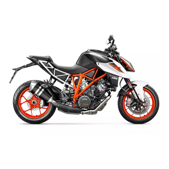
- Page 1 OWNER'S MANUAL 2017 1290 Super Duke R Art. no. 3213534en...
- Page 3 KTM accepts no liability for delivery options, devi- ations from illustrations and descriptions, misprints, and other errors.
- Page 4 Reproduction, even in part, as well as copying of all kinds, is permitted only with the express written permission of the copyright owner. ISO 9001(12 100 6061) According to the international quality management standard ISO 9001, KTM uses quality assurance processes that lead to the maximum possible quality of the products.
-
Page 5: Table Of Contents
TABLE OF CONTENTS Fork part number ..........24 TABLE OF CONTENTS MEANS OF REPRESENTATION ........8 Shock absorber article number ......25 Symbols used ............8 Steering damper article number ......25 Formats used............9 CONTROLS..............26 SAFETY ADVICE............10 Use definition –... - Page 6 Favorites ............55 7.21 Bluetooth (optional) .......... 72 ® 7.13.2 Set Favorites ..........56 7.22 KTM MY RIDE (optional) ........72 7.13.3 Trip 1 ............56 7.23 Pairing (optional) ..........73 7.13.4 Trip 2 ............57 7.24 Audio (optional) ..........75 7.13.5...
- Page 7 TABLE OF CONTENTS Adjusting the basic position of the foot brake 12 SUSPENSION SETTING..........113 lever .............. 80 12.1 Fork/shock absorber ......... 113 Setting the step plate of the foot brake lever..81 12.2 Adjusting the compression damping of the Checking the basic position of the shift lever ..
- Page 8 TABLE OF CONTENTS 13.9 Mounting the passenger seat......129 15.6 Checking the tire air pressure......165 13.10 Removing the front rider's seat ......130 16 ELECTRICAL SYSTEM ..........167 13.11 Mounting the front rider's seat......130 16.1 Daytime running light (DRL)....... 167 13.12 Mounting the helmet lock on the vehicle ....
- Page 9 TABLE OF CONTENTS 20 CLEANING, CARE ............203 30 LIST OF SYMBOLS............237 20.1 Cleaning the motorcycle ........203 30.1 Red symbols............ 237 20.2 Checks and maintenance steps for winter 30.2 Yellow and orange symbols........ 237 operation............205 30.3 Green and blue symbols........238 21 STORAGE ..............
-
Page 10: Means Of Representation
All work marked with this symbol requires specialist knowledge and technical understanding. In the interest of your own safety, have these jobs performed by an authorized KTM workshop. There, your motorcycle will be optimally cared for by specially trained experts using the specialist tools required. -
Page 11: Formats Used
MEANS OF REPRESENTATION Formats used The typographical formats used in this document are explained below. Specific name Identifies a proprietary name. Name ® Identifies a protected name. Brand™ Identifies a brand available on the open market. Underlined terms Refer to technical details of the vehicle or indicate technical terms that are explained in the glossary. -
Page 12: Safety Advice
SAFETY ADVICE Use definition – intended use KTM Street motorcycles are designed and constructed to meet the normal demands of regular road operation and also for use on race courses. They are not designed for offroad use. Info The motorcycle is only authorized for operation on public highways in the homologated version. -
Page 13: Degrees Of Risk And Symbols
SAFETY ADVICE Degrees of risk and symbols Danger Indicates a danger that will immediately and invariably lead to fatal or serious permanent injury if the appropriate measures are not taken. Warning Indicates a danger that is likely to lead to fatal or serious injury if the appropriate measures are not taken. Caution Indicates a danger that may lead to minor injuries if the appropriate measures are not taken. -
Page 14: Safe Operation
The vehicle should only be used by trained persons. An appropriate driver's license is needed to ride the vehicle on public roads. Have malfunctions that impair safety promptly eliminated by an authorized KTM workshop. Adhere to the information and warning labels on the vehicle. -
Page 15: Protective Clothing
– Always wear protective clothing that is in good condition and meets the legal regulations. In the interest of your own safety, KTM recommends that you only operate the vehicle while wearing protective clothing. Work rules Special tools are necessary for certain tasks. The tools are not contained in the vehicle but can be ordered under the number in parenthe- ses. -
Page 16: Owner's Manual
Keep the Owner's Manual in an accessible place to enable you to refer to it as needed. If you would like to know more about the vehicle or have questions on the material you read, please contact an authorized KTM dealer. -
Page 17: Important Notes
Manufacturer and implied warranty The work specified in the service schedule may only be performed in an authorized KTM workshop and must be recorded in both the Service & Warranty Booklet and in KTM Dealer.net, otherwise any warranty coverage will become void. Damage or secondary damage caused by tampering with and/or conversions on the vehicle are not covered by the warranty. -
Page 18: Service
Please follow the instructions in the text. Customer service Your authorized KTM dealer will be happy to answer any questions you may have on your vehicle and KTM. A list of authorized KTM dealers can be found on the KTM website. -
Page 20: View Of Vehicle
VIEW OF VEHICLE View of vehicle, front left (example) S01711-10... - Page 21 VIEW OF VEHICLE Clutch lever ( p. 26) Supporting strap ( p. 41) Tool set ( p. 39) Seat lock ( p. 38) Passenger footrests ( p. 42) Shock absorber, spring pretension setting Rider footrests Shift lever ( p. 42) Side stand ( p.
-
Page 22: View Of Vehicle, Rear Right (Example)
VIEW OF VEHICLE View of vehicle, rear right (example) S01708-10... - Page 23 VIEW OF VEHICLE Filler cap Combination switch, left side ( p. 27) Steering lock ( p. 34) Emergency OFF switch/electric starter button ( p. 33) Race‑on button ( p. 34) Throttle grip ( p. 27) Hand brake lever ( p. 26) Fork compression adjustment Fork rebound adjustment Foot brake lever (...
-
Page 24: Serial Numbers
SERIAL NUMBERS Chassis number The chassis number is stamped on the right side of the steering head. The chassis number is also shown on the type label. 402324-10 Type label (Super Duke R EU/JP) The type label is located on the steering head. 0 0 1 402302-10... -
Page 25: Key Number
SERIAL NUMBERS (Super Duke R AU) The type label is located on the frame on the left. 402293-10 Key number The key number Code number can be found on the KEYCODECARD. Info You need the key number to order a spare key. Keep the KEYCODECARD in a safe place. -
Page 26: Engine Number
SERIAL NUMBERS Engine number The engine number is stamped on the right side of the engine. 402296-10 Fork part number The fork part number is stamped on the inside of the axle clamp. 402295-10... -
Page 27: Shock Absorber Article Number
SERIAL NUMBERS Shock absorber article number The shock absorber article number is stamped on the top of the shock absorber above the adjusting ring towards the engine side. 402798-10 Steering damper article number Steering damper item number is embossed on the underside of the steering damper. H01060-10... -
Page 28: Controls
CONTROLS Clutch lever Clutch lever is fitted on the handlebar on the left. The clutch is activated hydraulically and adjusts itself automatically. S01712-10 Hand brake lever The hand brake lever is fitted on the right side of the handlebar. The front brake is engaged using the hand brake lever. S01709-10... -
Page 29: Throttle Grip
CONTROLS Throttle grip The throttle grip is fitted on the right side of the handlebar. S01710-10 Combination switch, left side The left combination switch is fitted on the left side of the handlebar. Overview of the left combination switch Light switch ( p. -
Page 30: Light Switch
CONTROLS Light switch The light switch is fitted on the combination switch on the left. Possible states Low beam on – Light switch in position . In this position, the low beam and the tail light are switched on. High beam on – Light switch in position . -
Page 31: Turn Signal Switch
CONTROLS Turn signal switch Turn signal switch is fitted on the combination switch on the left. Possible states Turn signal off – Turn signal switch pushed toward the switch housing. Left turn signal, on – Turn signal switch pressed to the left. The turn signal switch returns automatically to the central position after use. -
Page 32: Horn Button
CONTROLS Horn button The horn button is fitted on the combination switch on the left. Possible states • Horn button in basic position. pressed – The horn is operated in this position. • Horn button S01716-11 Cruise control system tip switch cruise control system tip switch is fitted on the left side of the combination switch. - Page 33 CONTROLS Info After activation of the cruise control system function, the throttle grip can be turned back to the home position. The selected speed will be maintained. If the target speed is exceeded for less than 30 seconds when turning the throttle grip, the cruise control system remains activated.
-
Page 34: Combination Switch, Right
CONTROLS Warning Danger of accidents The cruise control system function is not suitable for all driving situations. The selected target speed will not be reached,if the engine power is not sufficient for a gradient. The selected target speed will be exceeded if the engine braking effect is not suffi- cient on a decline. -
Page 35: Hazard Warning Flasher Switch
CONTROLS 6.11 Hazard warning flasher switch The hazard warning flasher switch is fitted on the right side of the combination switch. The hazard warning flasher is used to indicate emergency situations. Info The hazard warning flasher can be activated or deactivated while the ignition is switched on or up to 60 seconds after the ignition is switched off. -
Page 36: Race-On Button
CONTROLS 6.13 Race‑on button The Race‑on button is fitted on the right side of the combination switch. Info The Race‑on button performs the ignition lock function on this vehicle. The steering can only be locked if the handlebar is turned fully to the left. Possible states •... -
Page 37: Immobilizer
CONTROLS Ignition off, steering unlocked – In this operating mode, the ignition circuit is inter- • rupted and the steering unlocked. Ignition on, steering unlocked – In this operating mode, the ignition circuit is closed • and the steering unlocked. 6.15 Immobilizer The electronic immobilizer secures the vehicle against unauthorized use. -
Page 38: Opening The Filler Cap
A lost key must be deactivated by an authorized KTM workshop to prevent unauthorized persons from operating the vehicle. The keys supplied are activated when delivered. A total of up to four keys can be activated from an authorized KTM workshop. The key num- ber must be provided in each case. 6.17... - Page 39 CONTROLS Warning Danger of poisoning Fuel is poisonous and a health hazard. – Avoid skin, eye and clothing contact with fuel. – Immediately consult a doctor if you swallow fuel. – Do not inhale fuel vapors. – In case of skin contact, rinse the affected area with plenty of water. –...
-
Page 40: Closing The Filler Cap
CONTROLS 6.18 Closing the filler cap Warning Fire hazard Fuel is highly flammable, toxic and a health hazard. – Check the filler cap is locked correctly after closing. – Change your clothing in case of fuel spills on them. – Rinse the affected area immediately with plenty of water in the event of con- tact with the skin. -
Page 41: Baggage Lugs
CONTROLS 6.20 Baggage lugs The baggage lugs are located on the bottom of the passenger seat. Info When the passenger seat is mounted, the lugs are accessible if they are turned out- ward. No more than one small piece of luggage with the specified weight may be attached to the turned-out baggage lugs. -
Page 42: Opening Storage Compartment
CONTROLS 6.22 Opening storage compartment Info A storage compartment for flat items is located under the passenger seat. Preparatory work – Remove the passenger seat. ( p. 129) Main work – Press in area in order to open the storage compartment. –... -
Page 43: Helmet Lock
CONTROLS Finishing work – Mount the passenger seat. ( p. 129) 6.24 Helmet lock Warning Danger of accidents An attached helmet lock or an attached helmet impair the han- dling characteristic. – Do not use the helmet lock to attach a helmet or another object while riding. –... -
Page 44: Passenger Footrests
CONTROLS 6.26 Passenger footrests The passenger footrests can be folded up and down. Possible states Passenger footrests folded up – For operation without a passenger. • Passenger footrests folded down – For operation with a passenger. • S01726-10 6.27 Shift lever The shift lever is fitted on the left side of the engine. -
Page 45: Foot Brake Lever
CONTROLS The gear positions can be seen in the figure. The idle position is between the first and second gears. 402299-11 6.28 Foot brake lever Foot brake lever is located in front of the right footrest. The rear brake is engaged with the foot brake lever. 402301-10... -
Page 46: Side Stand
CONTROLS 6.29 Side stand The side stand is located on the left side of the vehicle. The side stand is used for parking the motorcycle. Info The side stand must be folded up during motorcycle use. The side stand is coupled with the safety starting system; see the instructions in the "Stopping, parking"... -
Page 47: Combination Instrument
COMBINATION INSTRUMENT Combination instrument The combination instrument is attached in front of the handlebar. The combination instrument is divided into two function areas. Display Indicator lamps ( p. 48) E00727-10 Activation and test Activation The combination instrument is activated when the ignition is switched on. Info The brightness of the displays is controlled by a brightness sensor in the combina- tion instrument. -
Page 48: Day-Night Mode
COMBINATION INSTRUMENT Day-Night mode Day mode is shown in a bright color. S01735-10 Night mode is shown in a dark color. Info The light sensor in the combination instrument measures the brightness of the envi- ronment and automatically switches the display to day or night mode. The display is brightened, darkened or switched to the other mode depending on the brightness measured by the light sensor. -
Page 49: Warning Notes
COMBINATION INSTRUMENT Warning notes If the general warning lamp lights up among the indicator lamps ( p. 48), the corre- sponding message appears in the display. The Set button is used to confirm receipt of the information and the message is cleared. All existing warning notes are displayed in the Warning menu until these are no longer active. -
Page 50: Indicator Lamps
COMBINATION INSTRUMENT Indicator lamps M01492-01... - Page 51 COMBINATION INSTRUMENT The indicator lamps offer additional information about the operating state of the motorcycle. When the ignition is switched on, all indicator lamps light up briefly. Possible states The left turn signal indicator lamp flashes green with a steady rhythmic flash – The left turn signal is switched on. Malfunction indicator lamp lights up/flashes yellow –...
-
Page 52: Display
COMBINATION INSTRUMENT Display M01493-10... - Page 53 COMBINATION INSTRUMENT Info The figure shows the standard display of the combination instrument. If the menu is opened, the speed is still displayed. When drive mode is activated TRACK (optional), the elements shown change and the display colors change. Tachometer Shift warning light ( p.
-
Page 54: Shift Warning Light
COMBINATION INSTRUMENT Shift warning light The shift warning light is integrated in the tachometer display. In the Shift Light menu, the engine speed for the shift warning light can be set. The shift warning light is always active during the running-in phase (up to 1,000 km / 621 mi). The shift warning light can only be deactivated, and the values for RPM1 and RPM2 can only be adjusted after this. -
Page 55: Time
COMBINATION INSTRUMENT Time The time is displayed in 24 hour format in all languages except for EN-US. The time is dis- played in 12 hour format if the language is set to EN-US. The time can be configured in the Clock/Date menu. Info The time must be reset after the battery was disconnected or the fuse was removed. -
Page 56: Trip Distance Counter
COMBINATION INSTRUMENT 7.11 Trip distance counter In the main display, Trip 1 is displayed as the trip distance counter by default. This cannot be changed. Information about the total riding distance covered can be accessed in the General Info menu under menu item ODO. The trip distance counter can be configured in the Trip 1 menu. -
Page 57: Menu
COMBINATION INSTRUMENT 7.13 Menu Info Press the SET button in the standard display to open the menu. Navigate through the menu using the UP button or the DOWN button Press the BACK button to close the current menu or the menu overview. S01715-13 7.13.1 Favorites... -
Page 58: Set Favorites
COMBINATION INSTRUMENT 7.13.2 Set Favorites Condition • The vehicle is stationary. – Press the SET button when the menu is closed. – Press the UP or DOWN button until the Set Favorites menu appears on the display. – Press SET button. –... -
Page 59: Trip 2
COMBINATION INSTRUMENT 7.13.4 Trip 2 – Press the SET button when the menu is closed. – Press the UP or DOWN button until the Trip 2 menu appears on the display. Trip 2 shows the distance since the last reset, such as between two refueling stops. Trip 2 is running and counts up to 9999. -
Page 60: Language
COMBINATION INSTRUMENT 7.13.6 Language Condition • The vehicle is stationary. – Press the SET button when the menu is closed. – Press the UP or DOWN button until the Settings menu appears on the display. – Press SET button. – Press the UP or DOWN button until the Language menu appears marked on the display. -
Page 61: Fuel Cons
COMBINATION INSTRUMENT 7.13.8 Fuel Cons Condition • The vehicle is stationary. – Press the SET button when the menu is closed. – Press the UP or DOWN button until the Settings menu appears on the display. – Press SET button. –... -
Page 62: 7.13.10 Temp
COMBINATION INSTRUMENT 7.13.10 Temp Condition • The vehicle is stationary. – Press the SET button when the menu is closed. – Press the UP or DOWN button until the Settings menu appears on the display. – Press SET button. – Press the UP or DOWN button until the Unit Settings menu appears on the display. -
Page 63: 7.13.12 Service
COMBINATION INSTRUMENT 7.13.12 Service Condition • The vehicle is stationary. – Press the SET button when the menu is closed. – Press the UP or DOWN button until the Settings menu appears on the display. – Press SET button. – Press the UP or DOWN button until the Service menu appears marked on the display. -
Page 64: 7.13.14 Shift Light
COMBINATION INSTRUMENT 7.13.14 Shift Light Condition • The vehicle is stationary. • ODO > 1000 km (621 mi). – Press the SET button when the menu is closed. – Press the UP or DOWN button until the Settings menu appears on the display. –... -
Page 65: Quick Selector 1
COMBINATION INSTRUMENT Warning Danger of accidents When visibility is poor, the daytime running light is not a substitute for the low beam. Automatic switching between the daytime running light and low beam may only be partially available when visibility is significantly impaired due to fog, snow or rain. -
Page 66: Quick Selector 2
COMBINATION INSTRUMENT – Press the SET button to confirm the selection. Information can be selected in the Quick Selector 1 menu. When the menu is closed, the Quick Selector 1 menu is opened by pressing the UP button. 7.13.17 Quick Selector 2 Condition The drive mode TRACK (optional) is not activated. -
Page 67: 7.13.18 Extra Functions
Use the UP or DOWN button to navigate through the extra functions. K00790-01 Info The optional extra functions are listed in Extra Functions. The current KTM Power- Parts and the available software for your vehicle can be found on the KTM web- site. 7.13.19 General Info –... -
Page 68: 7.13.20 Warning
COMBINATION INSTRUMENT 7.13.20 Warning Condition • Message or warning is present. – Press the SET button when the menu is closed. – Press the UP or DOWN button until the Warning menu appears on the display. – Press the SET button. –... -
Page 69: 7.13.22 Ride Mode
COMBINATION INSTRUMENT The commands Keep pressed and Release button are displayed on the combination instrument. In the MTC/ABS menu, MTC and ABS can be switched off. In ABS Mode you can select between ROAD and SMOTO. Info After the ignition is switched on, motorcycle traction control and ABS are enabled again. -
Page 70: Tpms
COMBINATION INSTRUMENT 7.14 TPMS Condition • Model with TPMS. Warning Danger of accidents The tire pressure control system does not eliminate the necessity to check the tires before going on a ride. To avoid false alarms, the tire pressure values are evaluated over a period of several minutes. -
Page 71: Heated Grips (Optional)
COMBINATION INSTRUMENT 7.15 Heated grips (optional) Condition • The vehicle is stationary. – Press the SET button. – Press the UP or DOWN button until Heated grips appears marked on the display. Pressing the SET button again switches the heated grips menu on or off. K00760-01 7.16 Heating (optional) -
Page 72: Quick Shift + (Optional)
COMBINATION INSTRUMENT 7.17 Quick Shift + (optional) Condition • The vehicle is stationary. – Press the SET button when the menu is closed. – Press the UP or DOWN button until the Settings menu appears on the display. Press the SET button to open the menu. –... -
Page 73: Launch Control (Optional)
COMBINATION INSTRUMENT 7.19 Launch Control (optional) Condition • The drive mode TRACK (optional) is activated. – Press the SET button when the menu is closed. – Press the UP or DOWN button until the menu item Launch Control is marked. Warning Danger of accidents When Anti Wheelie Mode is disabled, the motorcycle trac- tion control no longer counteracts the raising of the front wheel. -
Page 74: Bluetooth ® (Optional)
Press the SET button when the menu is closed. – Press the UP or DOWN button until the KTM MY RIDE menu appears on the display. Press the SET button to open the menu. In KTM MY RIDE an appropriate cellphone or headset can be paired with the combination instrument via Bluetooth ®... -
Page 75: Pairing (Optional)
– Press the SET button when the menu is closed. – Press the UP or DOWN button until the KTM MY RIDE menu appears on the display. Press the SET button to open the menu. – Press the UP or DOWN button until KTM MY RIDE Setup appears marked on the display. - Page 76 COMBINATION INSTRUMENT Info The following steps are identical for cellphones and headsets. – Press the SET button. – When pairing the device for the first time, press the UP or DOWN button until Pairing is marked. Press the SET button to open the menu. –...
-
Page 77: Audio (Optional)
Headset connected to suitable audio device. – Press the SET button when the menu is closed. – Press the UP or DOWN button until the KTM MY RIDE menu appears on the display. Press the SET button to open the menu. K00784-01 Warning Danger of accidents Headphone volume which is too high distracts attention... -
Page 78: Telephony (Optional)
COMBINATION INSTRUMENT 7.25 Telephony (optional) Condition • KTM MY RIDE Function activated (optional). • Function Bluetooth ® activated. • Similarly, the Bluetooth ® function is also activated when devices are paired. • Headset linked with appropriate cellphone. Warning Danger of accidents Headphone volume which is too high distracts attention from traffic activity. -
Page 79: Ergonomics
The handlebar can be mounted in two different positions. In this way, the handlebar can be mounted in the most comfortable position for the rider. Info KTM recommends the front handlebar position when using the vehicle on a race track. S01727-11... - Page 80 ERGONOMICS – Remove screws . Take off the handlebar clamps . Position the handlebar so that 0 0 A 0 0 1 screws are accessible. 0 0 2 0 0 B Info Cover the components to protect them against damage. 0 0 4 Do not kink the cables and lines.
-
Page 81: Adjusting The Basic Position Of The Clutch Lever
ERGONOMICS Adjusting the basic position of the clutch lever – Push the clutch lever lever forward. – Adjust the basic position of the clutch lever to your hand size by turning adjusting screw Info Turn the adjusting screw clockwise to increase the distance between the clutch lever and the handlebar. -
Page 82: Adjusting The Basic Position Of The Foot Brake Lever
ERGONOMICS Adjusting the basic position of the foot brake lever – Loosen nut – Press the foot brake lever down to be able to turn push rod more easily. – Turn the push rod until the foot brake lever is in the desired position. Info The range of adjustment is limited. -
Page 83: Setting The Step Plate Of The Foot Brake Lever
ERGONOMICS Setting the step plate of the foot brake lever – Remove screw together with the step plate of the foot brake lever. – To adjust the length of the foot brake lever, position the step plate of the foot brake lever using screw in a drill hole Guideline... -
Page 84: Adjusting The Basic Position Of The Shift Lever
ERGONOMICS – Sit on the vehicle in the riding position and determine distance between the upper edge of your boot and the shift lever. Distance between shift lever and upper 10… 20 mm (0.39… 0.79 in) edge of boot » If the distance does not meet specifications: 0 0 0 A –... -
Page 85: Setting The Shift Lever Stub
ERGONOMICS – Tighten nut , holding the threaded rod Guideline Nut, shift rod M8LH 12 Nm (8.9 lbf ft) Setting the shift lever stub – Remove screw along with the shift lever stub. – Position the shift lever stub with the screw in one of the drilled holes depending on the desired lever length. -
Page 86: Adjusting The Tilt Of The Combination Instrument
ERGONOMICS 8.10 Adjusting the tilt of the combination instrument Info The tilt of the combination instrument can be continuously adjusted using clamping on the handlebar. – Unplug the connector with sleeve. E00715-11 – Remove cable guide from the turn signal bracket cover. E00725-10... - Page 87 ERGONOMICS – Loosen screw using Allen key from the tool set. Allen key with ball head (61329099200) – Adjust the tilt of the combination instrument. Info The combination instrument must also not touch any other components follow- ing completion of the work. –...
- Page 88 ERGONOMICS – Plug in the connector with sleeve. E00715-11...
-
Page 89: Preparing For Use
Warning Danger of accidents Non-approved or non-recommended tires and wheels impact the handling characteristic. – Only use tires/wheels approved by KTM with the corresponding speed index. Warning Danger of accidents New tires have reduced road grip. The contact surface on new tires is not yet roughened. -
Page 90: Running In The Engine
When using your vehicle, remember that others may feel disturbed by excessive noise. – Make sure that the pre-delivery inspection work has been carried out by an authorized KTM workshop. You receive a delivery certificate and the Service and Warranty Booklet at vehicle handover. -
Page 91: Loading The Vehicle
PREPARING FOR USE – Avoid fully opening the throttle! Loading the vehicle Warning Danger of accidents Total weight and axle loads influence the handling characteristic. The overall weight consists of: motorcycle ready for operation and with a full tank, driver and passenger with protective clothing and helmet, and luggage. - Page 92 PREPARING FOR USE Warning Danger of accidents A high payload alters the handling characteristic and increases the stopping distance. – Adapt your speed to your payload. Warning Danger of accidents Pieces of luggage which have slipped impair the handling characteristic. – Check that your luggage is fixed properly at regular intervals. Warning Fire hazard The hot exhaust system may burn luggage.
-
Page 93: Riding Instructions
RIDING INSTRUCTIONS 10.1 Checks and maintenance measures when preparing for use Info Before every trip, check the condition of the vehicle and ensure that it is roadworthy. The vehicle must be in perfect technical condition when it is being operated. –... -
Page 94: Starting
RIDING INSTRUCTIONS 10.2 Starting Danger Danger of poisoning Exhaust gases are toxic and inhaling them may result in unconsciousness and death. – Always make sure there is sufficient ventilation when running the engine. – Use an effective exhaust extraction system when starting or running the engine in an enclosed space. Caution Danger of accidents Electronic components and safety devices will be damaged if the battery is discharged or missing. - Page 95 RIDING INSTRUCTIONS – Make sure that the emergency OFF switch/electric starter button is in the middle posi- tion – Switch on ignition; to do this, briefly press the Race-on button (maximum of 1 sec- ond). The steering is unlocked. The function check of the combination instrument is run. The ABS indicator lamp goes out when you start off.
-
Page 96: Launch Control (Optional)
RIDING INSTRUCTIONS 10.3 Launch Control (optional) Launch Control is an optional vehicle electronics function. Launch control adjusts the engine speed in order to achieve the best possible acceleration. Launch control can be used for starting off for a maximum of three times in succession. Launch control is temporarily deactivated after the third starting off in order to protect the engine, transmission and cooling system from overloading. - Page 97 RIDING INSTRUCTIONS Condition The drive mode TRACK (optional) is activated. First gear is engaged. Motorcycle traction control does not have an error stored. Coolant temperature: > 60 °C (> 140 °F) Total riding distance covered: > 1,000 km (> 620 mi) –...
-
Page 98: Quickshifter+ (Optional)
RIDING INSTRUCTIONS 10.6 Quickshifter+ (optional) If the Quickshifter+ (optional) is activated, you can shift up and down without actuating the clutch. Because there is no need to close the throttle grip, uninterrupted gear shifts are possible. The quickshifter+ uses the shifter shaft position to check whether or not a shift should be initiated, and sends a corresponding signal to the engine control. - Page 99 RIDING INSTRUCTIONS Warning Danger of accidents If you change down at high engine speed, the rear wheel blocks and the engine races. – Do not change into a low gear at high engine speed. Warning Danger of accidents Adjustments to the vehicle distract attention from traffic activity. –...
- Page 100 RIDING INSTRUCTIONS Warning Danger of accidents Total weight and axle loads influence the handling characteristic. The overall weight consists of: motorcycle ready for operation and with a full tank, driver and passenger with protective clothing and helmet, and luggage. – Do not exceed the maximum permissible overall weight or the axle loads. Warning Danger of accidents Pieces of luggage which have slipped impair the handling characteristic.
- Page 101 Only use the quickshifter+ in the permitted speed range shown. Info If you hear unusual noises while riding, stop immediately, switch off the engine, and contact an authorized KTM workshop. – Shift into a higher gear when conditions allow (incline, road situation, etc.).
- Page 102 Switch off the engine if running at idle or standing for a long time. – If the oil pressure warning lamp lights up during a trip, stop immediately and switch off the engine. Contact an authorized KTM workshop. – If the malfunction indicator lamp lights up during a trip, please contact an autho- rized KTM workshop as soon as possible.
-
Page 103: Msr (Optional)
RIDING INSTRUCTIONS – If the quickshifter+ is enabled in the combination instrument, you can shift down in the speed range shown without pulling the clutch lever. Info The maximum engine speed before shifting down in revolutions per minute is shown in the figure. Depress the shift lever quickly back to the stop without changing the throttle twist grip position. -
Page 104: Applying The Brakes
Danger of accidents A spongy pressure point on the front or rear brake reduces braking efficiency. – Check the brake system and do not continue riding until the problem is eliminated. (Your authorized KTM workshop will be glad to help.) Warning Danger of accidents The brake system fails in the event of overheating. - Page 105 RIDING INSTRUCTIONS Warning Danger of accidents Excessively forceful application of the brakes blocks the wheels. The ABS effectiveness is only ensured if it is switched on. – Leave the ABS switched on in order to benefit from the protective effect. Warning Danger of accidents Driving aids can only prevent a rollover within the physical limitations.
-
Page 106: Stopping, Parking
RIDING INSTRUCTIONS 10.10 Stopping, parking Warning Risk of injury People who act without authorization endanger themselves and others. If a valid transponder is in range, the vehicle can be started. – Do not leave the vehicle unattended if the engine is running. –... -
Page 107: Transport
RIDING INSTRUCTIONS – Apply the brakes on the motorcycle. – Shift the transmission to idle – Switch off ignition - to do this briefly press the Race-on button (maximum of 1 second) with the ignition switched on. Info If the engine is switched off with the emergency OFF switch and the ignition remains switched on at the Race-on button, the power supply to most power consumers remains unbroken. -
Page 108: Refueling
RIDING INSTRUCTIONS – Switch off the engine. – Use tension belts or other suitable devices to secure the motorcycle against accidents or falling over. 401475-01 10.12 Refueling Danger Fire hazard Fuel is highly flammable. The fuel in the fuel tank expands when warm and can escape if overfilled. –... - Page 109 In some countries and regions, the available fuel quality and cleanliness may not be sufficient. This will result in problems with the fuel system. – Refuel only with clean fuel that meets the specified standards. (Your authorized KTM workshop will be glad to help.) Warning Environmental hazard Improper handling of fuel is a danger to the environment.
- Page 110 RIDING INSTRUCTIONS – Switch off the engine. – Open the filler cap. ( p. 36) – Fill the fuel tank with fuel up to the lower edge of the filler neck. Total fuel tank 18 l (4.8 US gal) Super unleaded (ROZ 95/RON 95/PON capacity, approx.
-
Page 111: Service Schedule
15,000 km (9,300 mi) after 1,000 km (620 mi) ○ ● ● ● ● Read out the fault memory using the KTM diagnostics tool. ● ● ● ● Check the exhaust valve control with the KTM diagnostics tool. ○... - Page 112 ● Change the air filter, clean the air filter box. ● ● ● ● Check the fuel pressure. ○ ● ● Check the CO adjustment using the KTM diagnostics tool. ○ ● ● Check the headlight setting. ( p. 185)
-
Page 113: Recommended Work
● Reset the service display using the KTM diagnostic tool. ○ ● ● ● ● Make the service entry in KTM Dealer.net and in the Service and Manufacturer Warranty Booklet. ○ One-time interval ● Periodic interval 11.3 Recommended work Every four years... - Page 114 SERVICE SCHEDULE Every four years Every year every 30,000 km (18,600 mi) every 15,000 km (9,300 mi) after 1,000 km (620 mi) ○ ● ● ● ● Grease all moving parts (e.g., side stand, hand lever, chain, ...) and check for smooth operation. ○...
-
Page 115: Suspension Setting
SUSPENSION SETTING 12.1 Fork/shock absorber The fork and the shock absorber offer many options of adapting the suspension to the riding style and the payload. Info The recommendations for the suspension setting are shown in Table . The table is located on the underside of the front rider's seat. These adjustments are guidelines and should always be the basis for a suspension setting. -
Page 116: Adjusting The Rebound Damping Of The Fork
SUSPENSION SETTING Guideline Compression damping Comfort 15 clicks Standard 12 clicks Sport 9 clicks Full payload 9 clicks Info Turn clockwise to increase damping; turn counterclockwise to reduce damping. 12.3 Adjusting the rebound damping of the fork Info The hydraulic rebound damping determines the fork suspension behavior. –... -
Page 117: Compression Damping Of The Shock Absorber
SUSPENSION SETTING Guideline Rebound damping Comfort 15 clicks Standard 12 clicks Sport 9 clicks Full payload 9 clicks Info Turn clockwise to increase damping; turn counterclockwise to reduce damping. 12.4 Compression damping of the shock absorber The compression damping of the shock absorber is divided into two ranges: high-speed and low-speed. -
Page 118: Adjusting The Low-Speed Compression Damping Of The Shock Absorber
The shock absorber is filled with highly compressed nitrogen. – Please follow the description provided. (Your authorized KTM workshop will be glad to help.) Info The effect of the low-speed setting can be seen in slow to normal compression of the shock absorber. -
Page 119: Adjusting The High-Speed Compression Damping Of The Shock Absorber
The shock absorber is filled with highly compressed nitrogen. – Please follow the description provided. (Your authorized KTM workshop will be glad to help.) Info The effect of the high-speed setting can be seen in fast compression of the shock absorber. -
Page 120: Adjusting The Rebound Damping Of The Shock Absorber
Risk of injury Parts of the shock absorber will fly off if the shock absorber is disassembled incorrectly. The shock absorber is filled with highly compressed nitrogen. – Please follow the description provided. (Your authorized KTM workshop will be glad to help.) – Turn adjusting screw clockwise up to the last perceptible click. - Page 121 SUSPENSION SETTING Main work – Measure the distance – as vertical as possible – between the rear axle and a fixed point, for example, a mark on the rear fairing. – Note down the value as dimension 400988-10 Finishing work –...
-
Page 122: Checking The Static Sag Of The Shock Absorber
SUSPENSION SETTING 12.9 Checking the static sag of the shock absorber – Measure dimension of rear wheel unloaded. ( p. 118) – Hold the motorcycle upright with the aid of an assistant. – Measure the distance between the rear axle and the fixed point again. –... - Page 123 SUSPENSION SETTING Info The spring pretension defines the initial status of the spring operation on the shock absorber. The best spring pretension setting is achieved when it is set for the weight of the rider and that of any baggage and a passenger, thus ensuring an ideal compromise between maneuverability and stability.
- Page 124 SUSPENSION SETTING – Tighten the spring by turning adjusting ring to measurement Guideline Spring preload Comfort 8 mm (0.31 in) Standard 8 mm (0.31 in) Sport 8 mm (0.31 in) Full payload 9 mm (0.35 in) Info Turn clockwise to increase the spring pretension; turn counterclockwise to reduce the spring pretension.
-
Page 125: Service Work On The Chassis
SERVICE WORK ON THE CHASSIS 13.1 Lifting the motorcycle with the rear lifting gear Note Danger of damage The parked vehicle can roll away or fall over. – Park the vehicle on a firm and level surface. – Place the adapter into the rear lifting gear. Lifting gear, rear (61329955000) –... -
Page 126: Lifting The Motorcycle With The Front Lifting Gear
SERVICE WORK ON THE CHASSIS – Secure the motorcycle against falling over. – Remove the rear wheel stand and lean the vehicle on side stand 402029-10 13.3 Lifting the motorcycle with the front lifting gear Note Danger of damage The parked vehicle can roll away or fall over. –... -
Page 127: Taking The Motorcycle From The Front Lifting Gear
SERVICE WORK ON THE CHASSIS 13.4 Taking the motorcycle from the front lifting gear Note Danger of damage The parked vehicle can roll away or fall over. – Park the vehicle on a firm and level surface. – Secure the motorcycle against falling over. –... -
Page 128: Removing The Motorcycle From The Work Stand (Inserted)
SERVICE WORK ON THE CHASSIS – The plastic bushing of the work stand should engage in the opening of the swingarm pivot. Select the right height and width of the work stand. Work stand (62529055100) – Raise the motorcycle. Info Check that the work stand is properly seated. - Page 129 SERVICE WORK ON THE CHASSIS – Remove the motorcycle from the work stand and rest it on the side stand. – Remove the work stand. Work stand (62529055100) R01907-10...
-
Page 130: Cleaning The Dust Boots Of The Fork Legs
SERVICE WORK ON THE CHASSIS 13.7 Cleaning the dust boots of the fork legs – Push dust boots of both fork legs downward. Info The dust boots should remove dust and coarse dirt particles from the fork tubes. Over time, dirt can accumulate behind the dust boots. If this dirt is not removed, the oil seals behind can start to leak. -
Page 131: Removing The Passenger Seat
SERVICE WORK ON THE CHASSIS 13.8 Removing the passenger seat – Insert the Race‑on key or the black Race‑on key into the seat lock and turn clock- wise. – Lift the passenger seat at the front and pull it out of the holder toward the front. –... -
Page 132: Removing The Front Rider's Seat
SERVICE WORK ON THE CHASSIS 13.10 Removing the front rider's seat Preparatory work – Remove the passenger seat. ( p. 129) Main work – Raise the rear of the front rider's seat. – Detach the front of the front rider's seat and remove it. E00694-10 13.11 Mounting the front rider's seat... -
Page 133: Mounting The Helmet Lock On The Vehicle
SERVICE WORK ON THE CHASSIS 13.12 Mounting the helmet lock on the vehicle Warning Danger of accidents An attached helmet lock or an attached helmet impair the handling characteristic. – Do not use the helmet lock to attach a helmet or another object while riding. –... - Page 134 SERVICE WORK ON THE CHASSIS – Remove screw with the washer. – Take off the main silencer. R01827-10 – Remove seal ring R01828-10...
-
Page 135: Installing The Main Silencer
SERVICE WORK ON THE CHASSIS 13.14 Installing the main silencer – Mount seal ring R01828-11 – Position the main silencer. – Mount screw with washer but do not tighten yet. Guideline Remaining screws, chassis 25 Nm (18.4 lbf ft) R01827-10... -
Page 136: Checking The Chain For Dirt
SERVICE WORK ON THE CHASSIS – Position the exhaust clamp. – Mount and tighten screw Guideline Screw, exhaust clamp on main silencer 8 Nm (5.9 lbf ft) – Tighten screw Guideline Remaining screws, chassis 25 Nm (18.4 lbf ft) R01826-11 13.15 Checking the chain for dirt –... - Page 137 SERVICE WORK ON THE CHASSIS Warning Danger of accidents Oil or grease on the brake discs reduces the braking effect. – Always keep the brake discs free of oil and grease. – Clean the brake discs with brake cleaner when necessary. Warning Environmental hazard Hazardous substances cause environmental damage.
-
Page 138: Checking The Chain Tension
SERVICE WORK ON THE CHASSIS 13.17 Checking the chain tension Warning Danger of accidents Incorrect chain tension damages components and results in accidents. If the chain is tensioned too much, the chain, engine sprocket, rear sprocket, transmission and rear wheel bearings wear more quickly. -
Page 139: Adjusting The Chain Tension
SERVICE WORK ON THE CHASSIS – Check locking caps for damage and firm seating. » If the locking caps are damaged or loose: – Replace the locking caps. Link fork locking cap (61304041100) H00380-11 Finishing work – Remove the rear of the motorcycle from the lifting gear. ( p. - Page 140 SERVICE WORK ON THE CHASSIS Main work – Loosen screw – Set the chain tension by turning the hub housing. Hook wrench (61329085000) Handle for ring wrench (60012060000) Info Turn clockwise to increase the chain tension; turn counterclockwise to reduce the chain tension.
-
Page 141: Checking The Chain, Rear Sprocket, Engine Sprocket, And Chain Guide
SERVICE WORK ON THE CHASSIS 13.19 Checking the chain, rear sprocket, engine sprocket, and chain guide Preparatory work – Lift the motorcycle with the rear lifting gear. ( p. 123) Main work – Check the rear sprocket and engine sprocket for wear. »... - Page 142 SERVICE WORK ON THE CHASSIS – Shift the transmission to idle – Pull the lower chain section with specified weight Guideline Weight, chain wear measurement 15 kg (33 lb.) – Measure distance of 18 chain rollers in the lower chain section. Info Chain wear is not always even, so you should repeat this measurement at differ- ent chain positions.
- Page 143 SERVICE WORK ON THE CHASSIS – Check the chain sliding guard for wear at the recess. » If chain rivet is no longer visible at bottom edge of the recess of the chain sliding guard: – Change the chain sliding guard. –...
- Page 144 SERVICE WORK ON THE CHASSIS – Check the chain sliding piece for wear. » If the lower edge of the chain is in line with or below the chain sliding piece: – Change the chain sliding piece. – Check that the chain sliding piece is firmly seated. »...
-
Page 145: Checking/Correcting The Fluid Level Of The Hydraulic Clutch
SERVICE WORK ON THE CHASSIS 13.20 Checking/correcting the fluid level of the hydraulic clutch Warning Skin irritation Brake fluid causes skin irritation. – Keep brake fluid out of the reach of children. – Wear suitable protective clothing and safety glasses. – Do not allow brake fluid to come into contact with the skin, the eyes or clothing. - Page 146 SERVICE WORK ON THE CHASSIS – Move the clutch fluid reservoir mounted on the handlebar to a horizontal position. – Check the fluid level. The fluid level must be between MIN and MAX markings. » If the fluid level does not meet specifications: –...
-
Page 147: Brake System
– Only use spare parts on the brake system which have been approved and recom- mended by KTM. – Only use tires/wheels approved by KTM with the corresponding speed index. – Maintain the specified tire air pressure. – Service work and repairs must be performed professionally. (Your authorized KTM workshop will be glad to help.) - Page 148 BRAKE SYSTEM Warning Danger of accidents Driving aids can only prevent a rollover within the physical limi- tations. It is not always possible to compensate for extreme riding situations, for exam- ple with luggage loaded with a high center of gravity, varying road surfaces, steep descents or full braking without disengaging the gear.
-
Page 149: Checking The Brake Discs
Danger of accidents Worn-out brake discs reduce the braking effect. – Make sure that worn-out brake discs are replaced immediately. (Your authorized KTM workshop will be glad to help.) – Check the thickness of the front and rear brake discs at multiple points on each brake... -
Page 150: Checking The Front Brake Fluid Level
If the brake fluid level drops below the MIN marking, the brake system is leaking or the brake linings are worn down. – Check the brake system and do not continue riding until the problem is eliminated. (Your authorized KTM workshop will be glad to help.) Warning Danger of accidents Old brake fluid reduces the braking effect. -
Page 151: Adding Front Brake Fluid
If the brake fluid level drops below the MIN marking, the brake system is leaking or the brake linings are worn down. – Check the brake system and do not continue riding until the problem is eliminated. (Your authorized KTM workshop will be glad to help.) Warning Skin irritation Brake fluid causes skin irritation. - Page 152 Danger of accidents Old brake fluid reduces the braking effect. – Make sure that brake fluid for the front and rear brake is changed in accordance with the service schedule. (Your authorized KTM workshop will be glad to help.) Warning Environmental hazard Hazardous substances cause environmental damage.
-
Page 153: Checking The Front Brake Linings
Warning Danger of accidents Worn-out brake linings reduce the braking effect. – Ensure that worn-out brake linings are replaced immediately. (Your authorized KTM workshop will be glad to help.) Warning Danger of accidents Damaged brake discs reduce the braking effect. If the brake linings are not changed in time, the brake lining carriers grind against the brake disc. As a consequence, the braking effect is greatly reduced and the brake discs are destroyed. -
Page 154: Checking The Rear Brake Fluid Level
If the brake fluid level drops below the MIN marking, the brake system is leaking or the brake linings are worn down. – Check the brake system and do not continue riding until the problem is eliminated. (Your authorized KTM workshop will be glad to help.) Warning Danger of accidents Old brake fluid reduces the braking effect. -
Page 155: Adding Rear Brake Fluid
If the brake fluid level drops below the MIN marking, the brake system is leaking or the brake linings are worn down. – Check the brake system and do not continue riding until the problem is eliminated. (Your authorized KTM workshop will be glad to help.) Warning Skin irritation Brake fluid causes skin irritation. -
Page 156: Checking The Brake Linings Of The Rear Brake
Clean up overflowed or spilled brake fluid immediately with water. 14.8 Checking the brake linings of the rear brake Warning Danger of accidents Worn-out brake linings reduce the braking effect. – Ensure that worn-out brake linings are replaced immediately. (Your authorized KTM workshop will be glad to help.) - Page 157 BRAKE SYSTEM Warning Danger of accidents Damaged brake discs reduce the braking effect. If the brake linings are not changed in time, the brake lining carriers grind against the brake disc. As a consequence, the braking effect is greatly reduced and the brake discs are destroyed. –...
-
Page 158: Wheels, Tires
WHEELS, TIRES 15.1 Removing the front wheel Preparatory work – Lift the motorcycle with the rear lifting gear. ( p. 123) – Lift the motorcycle with the front lifting gear. ( p. 124) Main work – Remove screws from both brake calipers. –... -
Page 159: Installing The Front Wheel
WHEELS, TIRES – Remove spacers 309489-10 15.2 Installing the front wheel – Check the wheel bearing for damage and wear. » If the wheel bearing is damaged or worn: – Change the front wheel bearing. – Clean and grease shaft seal rings and mating surfaces of the spacers. - Page 160 WHEELS, TIRES – Insert wide spacer on the left in the direction of travel. Info Arrow indicates the direction of travel of the front wheel. The ABS sensor wheel is on the left viewed in the direction of travel. – Insert the narrow spacer on the right in the direction of travel.
- Page 161 WHEELS, TIRES – Position the brake calipers and check that the brake linings are seated correctly. – Mount screws on both brake calipers but do not tighten yet. – Operate the hand brake lever repeatedly until the brake linings are in contact with the brake disc and there is a pressure point.
-
Page 162: Removing The Rear Wheel
WHEELS, TIRES 15.3 Removing the rear wheel Preparatory work – Lift the motorcycle with the rear lifting gear. ( p. 123) – Remove the main silencer. p. 131) Main work – Remove the inside locking wire – Remove the outside locking wire B04149-10 –... -
Page 163: Installing The Rear Wheel
WHEELS, TIRES – Take off the rear wheel. B04138-10 15.4 Installing the rear wheel Warning Danger of accidents Oil or grease on the brake discs reduces the braking effect. – Always keep the brake discs free of oil and grease. – Clean the brake discs with brake cleaner when necessary. - Page 164 WHEELS, TIRES Main work – Check the rear wheel bearing for damage and wear. » If the rear wheel bearing is damaged or worn: – Change the rear wheel bearing. – Clean and grease the threads of the wheel axle and axle nut. Long-life grease ( p.
-
Page 165: Checking The Tire Condition
Danger of accidents If a tire bursts while riding, the vehicle becomes uncontrollable. – Ensure that damaged or worn tires are replaced immediately. (Your authorized KTM workshop will be glad to help.) Warning Danger of crashing Different tire tread patterns on the front and rear wheel impair the handling characteristic. - Page 166 WHEELS, TIRES Warning Danger of accidents New tires have reduced road grip. The contact surface on new tires is not yet roughened. – Run in new tires with moderate riding at alternating angles. Running-in phase 200 km (124 mi) Info Tire type, tire condition, and tire air pressure influence the braking and handling characteristics of the vehicle. Worn tires are particularly unfavorable on wet surfaces.
-
Page 167: Checking The Tire Air Pressure
DOT number. The first two digits indicate the week of manufacture and the last two digits the year of manufacture. KTM recommends that the tires be changed after 5 years at the latest, regard- less of the actual state of wear. - Page 168 WHEELS, TIRES – Correct the tire pressure. – Mount the dust cap.
-
Page 169: Electrical System
ELECTRICAL SYSTEM 16.1 Daytime running light (DRL) Warning Danger of accidents When visibility is poor, the daytime running light is not a sub- stitute for the low beam. Automatic switching between the daytime running light and low beam may only be partially available when visibility is significantly impaired due to fog, snow or rain. -
Page 170: Removing The Battery
ELECTRICAL SYSTEM 16.2 Removing the battery Warning Risk of injury Battery acid and battery gases cause serious chemical burns. – Keep batteries out of the reach of children. – Wear suitable protective clothing and safety glasses. – Avoid contact with battery acid and battery gases. –... - Page 171 ELECTRICAL SYSTEM Main work – Remove screw – Lift cover at the rear and pull toward the rear. – Fold up the cover. T00488-10 – Disconnect negative cable of the battery. – Remove positive terminal cover and disconnect the positive cable from the battery. –...
-
Page 172: Installing The Battery
ELECTRICAL SYSTEM 16.3 Installing the battery Warning Risk of injury Battery acid and battery gases cause serious chemical burns. – Keep batteries out of the reach of children. – Wear suitable protective clothing and safety glasses. – Avoid contact with battery acid and battery gases. –... - Page 173 ELECTRICAL SYSTEM – Position the positive cable and mount and tighten the screw. Guideline Screw, battery terminal 4.5 Nm (3.32 lbf ft) – Mount positive terminal cover – Position negative cable ; mount and tighten the screw. Guideline Screw, battery terminal 4.5 Nm L01483-11 (3.32 lbf ft)
- Page 174 ELECTRICAL SYSTEM – Position cover Screw heads engage in recesses – Mount and tighten screw L01486-10 Finishing work – Mount the front rider's seat. ( p. 130) – Mount the passenger seat. ( p. 129) – Set the time and date.
-
Page 175: Recharging The Battery
ELECTRICAL SYSTEM 16.4 Recharging the battery Warning Risk of injury Battery acid and battery gases cause serious chemical burns. – Keep batteries out of the reach of children. – Wear suitable protective clothing and safety glasses. – Avoid contact with battery acid and battery gases. –... - Page 176 The battery is maintenance-free, i.e., the acid level does not have to be checked. If the battery is not charged using the KTM battery charger, the battery must be removed for charging. Otherwise, overvoltage may damage electronic components. Charge the battery according to the instructions on the battery housing.
- Page 177 ELECTRICAL SYSTEM – Disconnect negative cable of the battery to avoid damage to the motorcycle's elec- tronics. – Remove positive terminal cover L01483-12 – Connect the battery charger to the battery. Switch on the battery charger. Battery charger (58429074000) You can also use the battery charger to test the open-circuit voltage and start potential of the battery, and to test the alternator.
- Page 178 ELECTRICAL SYSTEM – Mount positive terminal cover – Position negative cable and mount and tighten the screw. Guideline Screw, battery terminal 4.5 Nm (3.32 lbf ft) L01483-12 – Position cover Screw heads engage in recesses – Mount and tighten screw L01486-11...
-
Page 179: Changing The Race-On Key Battery
ELECTRICAL SYSTEM Finishing work – Mount the front rider's seat. ( p. 130) – Mount the passenger seat. ( p. 129) – Set the time and date. 16.5 Changing the Race-on key battery – Fold out the key bit of the Race-on key. –... -
Page 180: Changing The Main Fuse
ELECTRICAL SYSTEM – Fit lower half of the Race-on key and snap into place in the direction of the arrow. S01740-11 16.6 Changing the main fuse Warning Fire hazard Incorrect fuses overload the electrical system. – Only use fuses with the required ampere value. –... - Page 181 ELECTRICAL SYSTEM Main work – Remove screw – Lift cover at the rear and pull toward the rear. – Fold up the cover. T00488-10 – Take off protection caps 500327-11 – Remove faulty main fuse Info You can recognize a faulty fuse by a burned-out fuse wire A spare fuse is located in the starter relay.
- Page 182 ELECTRICAL SYSTEM – Check that the electrical equipment is functioning properly. – Mount the protection caps. Insert a new spare fuse into the starter relay to have it available when needed. – Position cover Screw heads engage in recesses – Mount and tighten screw M01490-10 Finishing work...
-
Page 183: Changing The Fuses In The Fuse Box
ELECTRICAL SYSTEM – Set the time and date. 16.7 Changing the fuses in the fuse box Warning Fire hazard Incorrect fuses overload the electrical system. – Only use fuses with the required ampere value. – Do not bypass or repair fuses. Info The fuse box containing the fuses of individual power consumers is located under the seat. - Page 184 ELECTRICAL SYSTEM – Open fuse box cover 500329-11 – Check the fuses. Info You can recognize a faulty fuse by a burned-out fuse wire – Remove the defective fuse. E00680-10...
- Page 185 ELECTRICAL SYSTEM Guideline Fuse 1 - 10 A - power supply for control units and components Fuse 2 - 10 A - permanent positive for auxiliary equipment Fuse 3 - 10 A - permanent positive for headlight Fuse 4 - 10 A - permanent positive for headlight Fuse 5 - 10 A - ECU Fuse 6 - 25 A - ABS return pump Fuse 7 - 15 A - ABS hydraulic unit...
- Page 186 ELECTRICAL SYSTEM – Position cover Screw heads engage in recesses – Mount and tighten screw M01490-10 Finishing work – Mount the front rider's seat. ( p. 130) – Mount the passenger seat. ( p. 129)
-
Page 187: Checking The Headlight Setting
ELECTRICAL SYSTEM 16.8 Checking the headlight setting – Park the vehicle on a horizontal surface in front of a light-colored wall and make a mark at the height of the center of the low beam headlight. – Make another mark at a distance under the first mark. - Page 188 ELECTRICAL SYSTEM Main work – Turn adjusting screw to adjust the headlight range. Info Turn clockwise to increase the headlight range; turn counterclockwise to reduce the headlight range. If you have a payload, you may have to correct the headlight range. Screw also secures the headlight.
-
Page 189: Diagnostics Connector
ELECTRICAL SYSTEM 16.10 Diagnostics connector Diagnostics connector is located under the front rider's seat. H01949-01 16.11 ACC1 and ACC2 front Power supplies ACC1 and ACC2 front are located behind the right cover between the triple clamps. E00777-10... -
Page 190: Acc1 And Acc2 Rear
ELECTRICAL SYSTEM 16.12 ACC1 and ACC2 rear Power supplies ACC1 and ACC2 rear are located under the seat. E00778-10... -
Page 191: Cooling System
COOLING SYSTEM 17.1 Checking the coolant level in the compensating tank Warning Danger of scalding During motorcycle operation, the coolant gets very hot and is under pressure. – Do not open the radiator, the radiator hoses or other cooling system components if the engine or the cooling system are at oper- ating temperature. -
Page 192: Correcting The Coolant Level In The Compensating Tank
COOLING SYSTEM – Park the motorcycle on a horizontal surface. – Check the coolant level in the compensating tank The coolant level must be between MIN and MAX. » If there is no coolant in the compensating tank: – Check the cooling system for leaks. Info Do not start up the motorcycle! E00676-10... - Page 193 COOLING SYSTEM Warning Danger of poisoning Coolant is toxic and a health hazard. – Keep coolant out of the reach of children. – Do not allow coolant to come into contact with the skin, the eyes and clothing. – Consult a doctor immediately if coolant is swallowed. –...
- Page 194 COOLING SYSTEM Main work – Pull and take off the compensating tank from the side with the holding lug E00677-10 – Remove cover of the compensating tank. – Add coolant to the MAX marking. Coolant ( p. 229) – Mount cover of the compensating tank.
-
Page 195: Engine Tuning
ENGINE TUNING 18.1 Ride Mode Possible states SPORT – Homologated performance with very direct response; the traction control • allows greater slip on the rear wheel. STREET – Homologated performance with balanced response; the traction control • allows normal slip on the rear wheel. RAIN –... -
Page 196: Slip Adjustment (Optional)
ENGINE TUNING Info When traction control is active, the TC indicator lamp flashes. When traction control is switched off, the TC indicator lamp is lit. 18.3 Slip adjustment (optional) The slip adjustment is an optional motorcycle traction control function. The slip adjustment allows the motorcycle traction control to be tuned through nine levels to the desired characteristic map. -
Page 197: Service Work On The Engine
SERVICE WORK ON THE ENGINE 19.1 Checking the engine oil level Info Oil consumption depends on the riding style and the operating conditions. Condition The engine is at operating temperature. Preparatory work – Stand the motorcycle upright on a horizontal surface. Main work –... -
Page 198: Changing The Engine Oil And Oil Filter, Cleaning The Oil Screens
SERVICE WORK ON THE ENGINE 19.2 Changing the engine oil and oil filter, cleaning the oil screens Warning Danger of scalding Engine and gear oil get very hot when the motorcycle is ridden. – Wear suitable protective clothing and safety gloves. –... - Page 199 SERVICE WORK ON THE ENGINE – Remove screws . Remove oil filter cover with the O-ring. E00673-11 – Pull oil filter out of the oil filter housing. Circlip pliers reverse (51012011000) – Completely drain the engine oil. – Thoroughly clean the parts and sealing surfaces. E00675-10 –...
- Page 200 SERVICE WORK ON THE ENGINE – Mount and tighten screws Guideline Remaining engine screws 6 Nm (4.4 lbf ft) E00673-10 – Thoroughly clean magnets and oil screens of the oil drain plugs. 100773-12 – Mount and tighten oil drain plugs with the magnets, O-rings, and oil screens.
- Page 201 SERVICE WORK ON THE ENGINE – Add the oil quantity in two separate operations. Engine oil 3.50 l (3.7 qt.) Outside Engine oil temperature: (SAE 10W/50) ≥ 0 °C (≥ 32 °F) p. 230) Outside Engine oil (SAE temperature: 5W/40) ( p.
-
Page 202: Adding Engine Oil
SERVICE WORK ON THE ENGINE – Remove the screw plug and add the remaining engine oil to upper marking on the engine oil level viewer. – Mount the screw plug. Danger Danger of poisoning Exhaust gases are toxic and inhaling them may result in unconsciousness and death. - Page 203 Outside temperature: < 0 °C (< 32 °F) Engine oil (SAE 5W/40) ( p. 230) E00670-12 Info In order to achieve optimal engine performance, it is not advisable to mix differ- ent engine oils. KTM recommends changing the engine oil. – Mount the screw plug.
- Page 204 SERVICE WORK ON THE ENGINE Danger Danger of poisoning Exhaust gases are toxic and inhaling them may result in unconsciousness and death. – Always make sure there is sufficient ventilation when running the engine. – Use an effective exhaust extraction system when starting or running the engine in an enclosed space.
-
Page 205: Cleaning, Care
CLEANING, CARE 20.1 Cleaning the motorcycle Note Material damage Components become damaged or destroyed if a pressure cleaner is used incorrectly. The high pressure forces water into the electrical components, connectors, throttle cables, and bearings, etc. Pressure which is too high causes malfunctions and destroys components. –... - Page 206 CLEANING, CARE – Close off the exhaust system to keep water from entering. – Remove loose dirt first with a soft jet of water. – Spray dirty parts with a normal commercial engine cleaner and then brush off with a soft brush.
-
Page 207: Checks And Maintenance Steps For Winter Operation
CLEANING, CARE – Treat bare metal (except for brake discs and the exhaust system) with a corrosion inhibitor. Preserving materials for paints, metal and rubber ( p. 233) – Treat the painted parts with a mild paint polish. Perfect Finish and high gloss polish for paints ( p. - Page 208 CLEANING, CARE – Clean the motorcycle. ( p. 203) – Clean the brakes. Info After EVERY trip on salted roads, thoroughly wash the brake calipers and brake linings with cold water and dry carefully. This should be done after the parts are cooled down and while they are installed.
-
Page 209: Storage
Recharge the battery. p. 173) – Store the vehicle in a dry location that is not subject to large fluctuations in tempera- ture. Info KTM recommends jacking up the motorcycle. – Lift the motorcycle with the rear lifting gear. ( p. 123) -
Page 210: Preparing For Use After Storage
STORAGE – Lift the motorcycle with the front lifting gear. ( p. 124) – Cover the vehicle with a tarp or similar cover that is permeable to air. Info Do not use non-porous materials since they prevent humidity from escaping, thus causing corrosion. -
Page 211: Troubleshooting
– Check the open-circuit current. – The safety start system is faulty Read out the fault memory using the KTM diag- nostics tool. – Electronic fault Read out the fault memory using the KTM diag- nostics tool. - Page 212 Stop the vehicle, switch off the ignition, and front and rear wheels start it again. – Malfunction in ABS Read out the fault memory using the KTM diag- nostics tool. – High oil consumption The engine oil level is too high Check the engine oil level.
-
Page 213: Technical Data
TECHNICAL DATA 23.1 Engine Design 2-cylinder 4-stroke Otto engine, 75° V arrangement, water-cooled Displacement 1,301 cm³ (79.39 cu in) Stroke 71 mm (2.8 in) Bore 108 mm (4.25 in) Compression ratio 13.6:1 Idle speed 1,400… 1,600 rpm Control DOHC, 4 valves per cylinder, chain-driven Valve - valve plate diameter Intake 42 mm (1.65 in) -
Page 214: Engine Tightening Torques
TECHNICAL DATA 1st gear 12:35 2nd gear 15:32 3rd gear 18:30 4th gear 20:27 5th gear 24:27 6th gear 27:26 Mixture preparation Electronically controlled fuel injection Ignition system Contactless controlled fully electronic ignition with digital ignition adjustment Alternator 12 V, 450 W Spark plug Inside spark plug NGK LKAR9BI‑10... - Page 215 TECHNICAL DATA – Screw, engine oil level viewer 4 Nm (3 lbf ft) Screw, gear sensor 6 Nm (4.4 lbf ft) Loctite ® 243™ Screw, pulse generator 6 Nm (4.4 lbf ft) Loctite ® 243™ Loctite ® 243™ Screw, resonator 8 Nm (5.9 lbf ft) –...
- Page 216 TECHNICAL DATA Screw, water pump wheel 10 Nm (7.4 lbf ft) Loctite ® 243™ – Stud, chain shaft 8 Nm (5.9 lbf ft) Vacuum connection 5 Nm (3.7 lbf ft) Loctite ® 243™ Loctite ® 243™ Nozzle 100 M6x0.75 4 Nm (3 lbf ft) –...
- Page 217 TECHNICAL DATA – Screw, conrod bearing M10x1 Step 1 25 Nm (18.4 lbf ft) Step 2 30 Nm (22.1 lbf ft) Step 3 90° – Screw, timing chain tensioner release M10x1 10 Nm (7.4 lbf ft) – Spark plug M10x1 11 Nm (8.1 lbf ft) Cylinder head screw M11x1.5...
-
Page 218: Capacities
TECHNICAL DATA 23.3 Capacities 23.3.1 Engine oil Outside temperature: ≥ 0 °C Engine oil 3.50 l (3.7 qt.) Engine oil (SAE 10W/50) (≥ 32 °F) p. 230) Outside temperature: < 0 °C Engine oil (SAE 5W/40) (< 32 °F) p. 230) 23.3.2 Coolant Coolant... - Page 219 TECHNICAL DATA Front Double disc brake with radially mounted four-pot brake calipers, floating brake discs Rear Single disc brake with dual-piston brake caliper, fixed brake disc Brake discs - diameter Front 320 mm (12.6 in) Rear 240 mm (9.45 in) Brake discs - wear limit front 4.5 mm (0.177 in)
-
Page 220: Electrical System
120/70 ZR 17 M/C (58W) TL 190/55 ZR 17 M/C (75W) TL Metzeler Sportec M7 RR Metzeler Sportec M7 RR The tires specified represent one of the possible series production tires. Additional information is available in the Service section under: http://www.ktm.com... -
Page 221: Fork
TECHNICAL DATA 23.7 Fork Fork article number 14.18.8Q.22 Fork WP Performance Systems 4860 ROTA SPLIT Compression damping Comfort 15 clicks Standard 12 clicks Sport 9 clicks Full payload 9 clicks Rebound damping Comfort 15 clicks Standard 12 clicks Sport 9 clicks Full payload 9 clicks Spring length with preload spacer(s) -
Page 222: Shock Absorber
TECHNICAL DATA 23.8 Shock absorber Shock absorber article number 15.18.7Q.22 Shock absorber WP Performance Systems 4618 BAVP DCC Compression damping, low-speed Comfort 20 clicks Standard 15 clicks Sport 12 clicks Full payload 12 clicks Compression damping, high-speed Comfort 1.5 turns Standard 1.5 turns Sport... -
Page 223: Chassis Tightening Torques
TECHNICAL DATA Medium (standard) 170 N/mm (971 lb/in) Spring length 185 mm (7.28 in) Gas pressure 10 bar (145 psi) Static sag Standard 20 mm (0.79 in) Race track mode 14 mm (0.55 in) Fitted length 384 mm (15.12 in) Shock absorber fluid ( p. - Page 224 TECHNICAL DATA – Remaining screws, chassis 5 Nm (3.7 lbf ft) – Screw for throttle grip 3.5 Nm (2.58 lbf ft) – Screw, cable channel 5 Nm (3.7 lbf ft) – Screw, chain sliding guard 5 Nm (3.7 lbf ft) –...
-
Page 225: Tightening Sequence
TECHNICAL DATA – Screw, exhaust clamp on manifold 8 Nm (5.9 lbf ft) Screw, foot brake cylinder 10 Nm (7.4 lbf ft) Loctite ® 243™ – Screw, fuel pump 6 Nm (4.4 lbf ft) – Screw, instrument support 2 Nm (1.5 lbf ft) –... -
Page 226: Nm (11.1 Lbf Ft)
TECHNICAL DATA – Nut, valve (Super Duke R JP) 4 Nm (3 lbf ft) – Nut, valve (Super Duke R EU/AU) 6 Nm (4.4 lbf ft) – Remaining nuts, chassis 25 Nm (18.4 lbf ft) – Remaining screws, chassis 25 Nm (18.4 lbf ft) –... - Page 227 TECHNICAL DATA Screw, front brake caliper 45 Nm (33.2 lbf ft) Loctite ® 243™ Screw, handlebar support 40 Nm (29.5 lbf ft) Loctite ® 243™ Screw, side stand 35 Nm (25.8 lbf ft) Loctite ® 243™ Loctite ® 243™ Screw, side stand bracket 45 Nm (33.2 lbf ft) Screw, side stand retaining plate 45 Nm (33.2 lbf ft)
-
Page 228: Declarations Of Conformity
Conformity is available at the following Internet address. Certification website: http://www.ktm.com/210m1100 KTM AG hereby declares that the KTM RACE ON system wireless system conforms with the relevant guidelines. The full text of the EU Decla- ration of Conformity is available at the following Internet address. - Page 229 DECLARATIONS OF CONFORMITY 210M1100 FCC ID: 2AKR7‑210M1100 IC: 22291‑210M1100 BT‑ROUTER FCC ID: Z64‑2564N IC: 451I‑2564N KTM RACE ON system ‑ Active Key FCC ID: VFZKLGKZADI01 IC: 22239-KLGKZADI01 KTM RACE ON system ‑ Main Unit FCC ID: VFZKLGMZADI01 IC: 22239-KLGMZADI01 LC8 DASHBOARD...
- Page 230 DECLARATIONS OF CONFORMITY 1 This device must not cause harmful interference. 2 This device must be able to absorb any received interference, including interference that potentially causes undesirable operation. This equipment has been tested and complies with the limits for Class B digital devices, in accordance with article 15 of the FCC regulations.
-
Page 231: Substances
SUBSTANCES Brake fluid DOT 4 / DOT 5.1 Standard/classification – Guideline – Use only brake fluid that complies with the specified standard (see specifications on the container) and that exhibits the corresponding properties. Recommended supplier Castrol – REACT PERFORMANCE DOT 4 Motorex ®... - Page 232 SUBSTANCES Observe the coolant manufacturer specifications for antifreeze protection, dilution and miscibility (compatibility) with other coolants. Recommended supplier Motorex ® – COOLANT M3.0 Engine oil (SAE 10W/50) Standard/classification – JASO T903 MA ( p. 234) – SAE ( p. 234) (SAE 10W/50) Guideline –...
- Page 233 SUBSTANCES Recommended supplier Motorex ® – Power Synt 4T Fork oil (SAE 4) (48601166S1) Standard/classification – SAE ( p. 234) (SAE 4) Guideline – Use only oils that comply with the specified standards (see specifications on the container) and that exhibit the corresponding proper- ties.
-
Page 234: Auxiliary Substances
AUXILIARY SUBSTANCES Chain cleaner Recommended supplier Motorex ® – Chain Clean Chain lube for road use Guideline Recommended supplier Motorex ® – Chainlube Road Fuel additive Recommended supplier Motorex ® – Fuel Stabilizer Long-life grease Recommended supplier Motorex ® – Bike Grease 2000 Motorcycle cleaner Recommended supplier... - Page 235 AUXILIARY SUBSTANCES Perfect Finish and high gloss polish for paints Recommended supplier Motorex ® – Moto Polish & Shine Preserving materials for paints, metal and rubber Recommended supplier Motorex ® – Moto Protect Special cleaner for glossy and matte paint finishes, metal and plastic surfaces Recommended supplier Motorex ®...
-
Page 236: Standards
STANDARDS JASO T903 MA Different technical development directions required a separate specification for 4-stroke motorcycles – the JASO T903 MA standard. Earlier, engine oils from the automobile industry were used for 4-stroke motorcycles because there was no separate motorcycle specifica- tion. -
Page 237: Index Of Special Terms
Light, which enhances the visibility of the vehicle during the day but is not focused, and in contrast to low beam does not illuminate the road surface KTM MY RIDE System for wireless communication with appropriate cellphones and headsets for telephony and audio... -
Page 238: List Of Abbreviations
LIST OF ABBREVIATIONS Art. no. Article number circa compare e.g. for example etc. et cetera i.a. inter alia number poss. possibly... -
Page 239: List Of Symbols
LIST OF SYMBOLS 30.1 Red symbols Red symbols indicate an error condition that requires immediate intervention. The oil pressure warning lamp lights up red – Engine oil pressure is too low. 30.2 Yellow and orange symbols Yellow and orange symbols indicate an error condition that requires prompt intervention. Active driving aids are also represented by yellow or orange symbols. -
Page 240: Green And Blue Symbols
LIST OF SYMBOLS 30.3 Green and blue symbols Green and blue symbols reflect information. The left turn signal indicator lamp flashes green with a steady rhythmic flash – The left turn signal is switched on. The idle indicator lamp lights up green – The transmission is in idle. The right turn signal indicator lamp flashes green with a steady rhythmic flash –... -
Page 241: Index
INDEX INDEX Brake linings front brake, checking ......151 ABS ........145 rear brake, checking . - Page 242 Warning ........66 KTM MY RIDE ....... . 72 warning notes .
- Page 243 INDEX Cruise control system operation ........30 Figures .
- Page 244 INDEX Handlebar position ......Main silencer adjusting ........77 installing .
- Page 245 INDEX Passenger seat Seat lock ........38 mounting .
- Page 246 INDEX opening ........40 Supporting strap ....... . . 41 Vehicle Suspension setting .
- Page 247 *3213534en* 3213534en 04/2017 KTM Sportmotorcycle GmbH Photo: Mitterbauer/KTM 5230 Mattighofen/Austria http://www.ktm.com...
Need help?
Do you have a question about the 1290 Super Duke R 2017 and is the answer not in the manual?
Questions and answers