
Subscribe to Our Youtube Channel
Related Manuals for dallmeier MDF3000A-CS


Summary of Contents for dallmeier MDF3000A-CS
- Page 1 Installation and Configuration English Module cameras MDF3000A-CS MDF3000A-M Rev. 2.0.0 / 080123...
- Page 2 All rights reserved. This document may not be copied, photocopied, reproduced, translated, transferred to an electronic medium or converted to a machine-readable form either whole or in part without first receiving written permission from Dallmeier electronic GmbH & Co.KG. We reserve the right to make technical modifications.
-
Page 3: Table Of Contents
Assembling mounting bracket (z-shaped) ........... 14 Installation ....................14 Doing the wiring ..................14 6.5.1 Video- / power cable ................... 14 6.5.2 DC auto iris (MDF3000A-CS only) .............. 15 6.5.3 Video connection ..................15 6.5.4 Power connection ..................15 Commissioning ................... 15 Preparing to configure ................ - Page 4 Exit Menu ....................26 Appendix ....................27 Menu structure .................... 27 Technical data ................... 28 10.1 MDF3000A-CS ................... 28 Technical drawing MDF3000A-CS .............. 30 10.2 MDF3000A-M ..................... 31 Technical drawing MDF3000A-M ..............33 10.3 Technical drawing mounting system ............34...
-
Page 5: About This Document
This document applies to the following module cameras: MDF3000A-CS MDF3000A-M It has been produced on the basis of software version 1.7 (MDF3000A-CS) and 2.3 (MDF3000A-M). The descriptions in this document apply to all module cameras. For simplification reasons, the term “MDF3000A“ is thus used for all cameras. - Page 6 MDF3000A-CS / MDF3000A-M IMPORTANT The word IMPORTANT denotes information for preventing damage, incorrect configurations or incorrect actions. NOTE A NOTE offers information on principles, special features and efficient procedure as well as general recommendations. Expression Expressions in bold and italics generally indicate a control element on the device (switches or labels) or on its user interface (buttons, menu entries).
-
Page 7: Safety Instructions
Do not make any modifications to the unit (neither to the software nor the hardware) without consulting Dallmeier electronic. Improper modifications can cause malfunctions or damages. Dallmeier electronic accepts no liability for damages resulting from unauthorized or improper modifications to the unit. - Page 8 MDF3000A-CS / MDF3000A-M Do not open the unit Do not open the housing of the unit. There are no components inside the unit that require maintenance by the user. The inspection, maintenance and repair with an open housing must only be carried out by trained and authorized professionals (installer).
-
Page 9: General Notes
Transportation and packaging Store the original packaging for transportation at a later date. Dallmeier electronic is not responsible for damage resulting from unprofessional/improper transportation. The goods should only be shipped in their original packaging. -
Page 10: Warranty
MDF3000A-CS / MDF3000A-M Advanced noise reduction Enhanced image quality by means of numerous control functions like AWB, AGC, BLC and extended slow shutter Wide dynamic range up to 120 dB Configuration via UTC commands Compact and lightweight design Quick and easy mounting... -
Page 11: Notes On Operating The Module Camera
MDF3000A-CS / MDF3000A-M Notes on operating the module camera The camera is powered by 12 V direct voltage. If the camera or the cable connected to the cable is located near sources of strong radiation, the video picture may be distorted. -
Page 12: Views And Connection Assignment
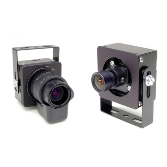
MDF3000A-CS / MDF3000A-M Views and connection assignment Views MDF3000A-CS MDF3000A-M Fig. 5-1 MDF3000A-CS MDF3000A-M 1. DC auto iris lens 1. Lens 2. CS lens mount 2. Thread mount: Ø 12 mm 3. Slotted head screw M 4 x 6 3. Slotted head screw M 4 x 6 with washer 4.3 mm... -
Page 13: Connection Assignment (Housing Back Side)
MDF3000A-CS / MDF3000A-M Connection assignment (housing back side) MDF3000A-CS MDF3000A-M A Pin 1 A Pin 1 B Pin 1 Fig. 5-2 Pin assignment A = Video and power interface Pin 1 = Video Ground Pin 2 = Video OUT Pin 3 = Ground... -
Page 14: Installation And Commissioning
MDF3000A-CS / MDF3000A-M Installation and commissioning Requirements at the installation site The MDF3000A is designed for indoor use. Unfavorable local conditions may shorten the life of the product or lead to malfunctions. Do not install/operate the camera in places: with large scale dust and dirt with steam or oil vapors (e.g. -
Page 15: Dc Auto Iris (Mdf3000A-Cs Only)
MDF3000A-CS / MDF3000A-M 6.5.2 DC auto iris (MDF3000A-CS only) Connect the DC auto iris cable to the module camera. IMPORTANT Ensure the correct pin assignment. 6.5.3 Video connection WARNING Danger of death from lightning strike! Do not connect the video cable during a thunderstorm. -
Page 16: Preparing To Configure
MDF3000A-CS / MDF3000A-M Preparing to configure The camera is supplied with factory settings which enable it to be used for most scenarios without further configuration. However, if required certain camera properties can be configured using the camera menu. The camera can be configured by means of the UTC Remote Box, the recorder or PView. -
Page 17: Dms Recorder
MDF3000A-CS / MDF3000A-M DMS Recorder Fig. 7-3 Camera Recorder CVBS monitor NOTE This method requires a recorder with software version 5.3.1 or higher and a built-in FG-11 frame grabber card. PView Fig. 7-4 Camera Recorder PView Station CVBS monitor NOTE This method requires a recorder with software version 5.3.1 or... -
Page 18: Configuration
MDF3000A-CS / MDF3000A-M Configuration The configuration dialog is opened as follows: UTC Remote Box: Press the OK button for approx. 2 seconds. DMS Recorder: Select Camera control > Open / Close menu PView: Select Camera control > Open / Close menu Navigating the configuration menu is always by means of 4 directions keys, which are referred to as Selector in the following. - Page 19 MDF3000A-CS / MDF3000A-M Details 1/2 Scenes full of contrast with strong backlights. Details are displayed in high resolution. The maximum dynamic scope of the camera is used. Indoor / Shadow Indoor scenes full of contrast with strong backlights. The relevant details are in the shadow.
- Page 20 MDF3000A-CS / MDF3000A-M As an alternative to the presets, the following settings can be manually changed to adapt the camera to the prevailing conditions: Brightness Select Brightness to adjust the image brightness. Gamma Gamma defines the brightness range within the color space and thus the differentiation between lights and shadows.
-
Page 21: Basic Functions
MDF3000A-CS / MDF3000A-M Basic Functions In the Basic Functions area you can make essential settings and specifications for picture display. 8.2.1 Camera ID Camera ID allows you to assign a unique name to the camera. --------- Basic Functions --------- The maximum length of the ID is 8 characters. -
Page 22: Horizontal Flip
MDF3000A-CS / MDF3000A-M NOTE The Sync = AC-Linelock function is not supported by the MDF3000A. NOTE Flicker Free Linelock is recommended if cameras without Linelock that are operated with a mains frequency of 50 Hz must be enhanced for scenarios with neon tubes. -
Page 23: Color
MDF3000A-CS / MDF3000A-M 8.2.5 Color The Color menu item allows you to toggle between color and --------- Basic Functions --------- black-and-white mode (Color = B/W). Previous Page. Camera ID. With B/W w/Burst the menu entries are displayed in color in CCTV System PAL.. -
Page 24: Image Functions
The “interlace effect” is thus prevented, whereas rapid movements are displayed in a more jerky manner. NOTE To record camera images with maximum resolution the Dallmeier recorder should be operated in full picture mode and the camera should be set to Progressive Scan = On. 8.3.2 Backlight When recording against backlighting, e.g. -
Page 25: Digital Zoom
MDF3000A-CS / MDF3000A-M Press the Enter button. The field of view is displayed in green. The field of view can be enlarged with the selector. Press the Enter button. The field of view is displayed in red. The field of view can be reduced with the selector. -
Page 26: Exit Menu
MDF3000A-CS / MDF3000A-M With ATW.. (Auto Tracking White Balance) the white balance is continually recalculated. The white balance is readjusted accordingly in different recording conditions. The WB Offset function can be used when the automatic white balance produces an unsatisfactory color display with "monochrome“ scenarios. This function modifies the mete- red color temperature. -
Page 27: Appendix
MDF3000A-CS / MDF3000A-M Appendix Menu structure ----------------- 3000 ------------------ > Presets.. Basic Functions.. Image Functions.. Save / Exit Menu.. --------------- Presets ---------------- Previous Page. > Presets Universal. Brightness Gamma Auto Range Bias Range Bias (Casino version only) Gain Limit Gain Limit (Casino version only) -
Page 28: 10 Technical Data
MDF3000A-CS / MDF3000A-M 10 Technical data 10.1 MDF3000A-CS Camera Image Sensor 1/3“ DPS CMOS Signal processing 17-bit Digital Signal Processing Video standard NTSC / PAL Video capture Progressive Scan Video capture rate 30 fps (NTSC), 25 fps (PAL) Video transfer format... - Page 29 MDF3000A-CS / MDF3000A-M Interfaces DC auto iris 4-Pin Molex socket Video / Power 4-Pin Hirose socket Video OUT CVBS, 1.0 Vp-p, 75Ω, BNC Environmental Conditions Temperature 0° to +35°C recommended Humidity 0% to 90% (non condensing) Electrical Data Power (incl. permitted tolerance) 12V DC ±...
-
Page 30: Technical Drawing Mdf3000A-Cs
MDF3000A-CS / MDF3000A-M Technical drawing MDF3000A-CS 46,30 44,80 37,50 15,90 30,70 11,13 46,30 Unit: mm Dallmeier electronic... -
Page 31: Mdf3000A-M
MDF3000A-CS / MDF3000A-M 10.2 MDF3000A-M Camera Image Sensor 1/3“ DPS CMOS Signal processing 17-bit Digital Signal Processing Video standard NTSC / PAL Video capture Progressive Scan Video capture rate 30 fps (NTSC), 25 fps (PAL) Video transfer format PsF (Progressive segmented Frame) - Page 32 MDF3000A-CS / MDF3000A-M Interfaces Video / Power 4-Pin Hirose socket Video OUT CVBS, 1.0 Vp-p, 75Ω, BNC Environmental Conditions Temperature 0° to +35°C recommended Humidity 0% to 90% (non condensing) Electrical Data Power (incl. permitted tolerance) 12V DC ± 5% Power consumption Approx.
-
Page 33: Technical Drawing Mdf3000A-M
MDF3000A-CS / MDF3000A-M Technical drawing MDF3000A-M 44,80 15,90 26,25 9,50 7,20 10,45 22,40 Unit: mm Dallmeier electronic... -
Page 34: Technical Drawing Mounting System
MDF3000A-CS / MDF3000A-M 10.3 Technical drawing mounting system 4,50 64,65 92,35 Unit: mm Dallmeier electronic... - Page 35 Council Directive on the Approximation of the Laws of the Member States relating to Electromagnetic Compatibility (89/336/EEC) and the Council Directive relating to Low Voltage 73/23/EEC. The following company is responsible for this declaration: Dallmeier electronic GmbH & Co.KG Cranachweg 1 D - 93051 Regensburg The measurements were carried out in accredited laboratories.
Need help?
Do you have a question about the MDF3000A-CS and is the answer not in the manual?
Questions and answers