Sign In
Upload
Download
Table of Contents
Contents
Add to my manuals
Delete from my manuals
Share
URL of this page:
HTML Link:
Bookmark this page
Add
Manual will be automatically added to "My Manuals"
Print this page
×
Bookmark added
×
Added to my manuals
Manuals
Brands
EXFO Manuals
Test Equipment
W2CM Series
User manual
EXFO W2CM Series User Manual
Test platform and interface module
Hide thumbs
1
2
Table Of Contents
3
4
5
6
7
8
9
10
11
12
13
14
15
16
17
18
19
20
21
22
23
24
25
26
27
28
29
30
31
32
33
34
35
36
37
38
39
40
41
42
43
44
45
46
47
48
49
50
51
52
53
54
55
56
57
58
59
page
of
59
Go
/
59
Contents
Table of Contents
Troubleshooting
Bookmarks
Table of Contents
Table of Contents
Certification Information
1 Introduction
QA-805 Features
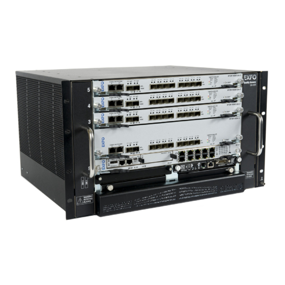
Front View of QA-805
Rear View of QA-805
Physical Description of QA-805 Unit
Cooling Assembly
Power Supplies
QA-805 Technical Specifications
Conventions
2 Safety Information
Laser Safety Warnings
Operating Cautions
Installation Instruction Warnings
Equipment Ratings
3 Getting Started
Shelf Installation
Turning the Unit On/Off
4 W2CM-10Gb Ethernet Interface Series
Module Installation
10/100/1000 M Copper and 1 G Optical Interfaces (SFP)
LAN/WAN Optical Interfaces (SFP+)
5 Maintenance
Maintaining Air Filters
Fan Tray Replacing
Power Supply Replacing
Recycling and Disposal (Applies to European Union Only)
6 Troubleshooting
Contacting the Technical Support Group
Transportation
7 Warranty
General Information
Liability
Exclusions
Certification
Service and Repairs
EXFO Service Centers Worldwide
A Technical Specifications
Qualityassurer - QA-805
W2CM 10 Gigabit Ethernet Interface Series
Index
Advertisement
Quick Links
Download this manual
User Guide
QA-805 and
2
W
CM Interface Module
Table of
Contents
Previous
Page
Next
Page
1
2
3
4
5
Advertisement
Table of Contents
Need help?
Do you have a question about the W2CM Series and is the answer not in the manual?
Ask a question
Questions and answers
Related Manuals for EXFO W2CM Series
Test Equipment EXFO EXFO MaxTester DSL User Manual
Fttx test set (58 pages)
Test Equipment EXFO IQS-12001B Brochure & Specs
Cable assembly and component test system (8 pages)
Test Equipment EXFO FIP-400 User Manual
Fiber inspection probe (41 pages)
Test Equipment EXFO FTV-700 series User Manual
Otdr for ftb-1 (327 pages)
Test Equipment EXFO MaxTester 635 Quick Reference Manual
(9 pages)
Test Equipment EXFO MaxTester series User Manual
(175 pages)
Test Equipment EXFO AXS-200/635 User Manual
Copper, vdsl2, adsl2 plus, and ip triple-play test set (267 pages)
Test Equipment EXFO FOT-930 MaxTester Manual
Multifunction loss tester (9 pages)
Test Equipment EXFO IQS-600 Series User Manual
Integrated qualification system (379 pages)
Test Equipment EXFO EX10 User Manual
Ethernet services broadband tester (65 pages)
Test Equipment EXFO FTBx-88000 Series User Manual
High-speed multiservice test module (1071 pages)
Test Equipment EXFO FIP-400B User Manual
(142 pages)
Test Equipment EXFO MaxTester 700 User Manual
(381 pages)
Test Equipment EXFO MAX-800 Series User Manual
Ethernet and transport tester, matester application (495 pages)
Test Equipment EXFO FOT-930 User Manual
Multifunction loss tester (111 pages)
Test Equipment EXFO RTU-310 User Manual
Ip services test head (547 pages)
This manual is also suitable for:
Quality assurer qa-805
Quality assurer qa-813
Quality assurer qa-604
W2cm-10gbe
W2cm-10gbe lite
W2cm-4gbe
Table of Contents
Print
Rename the bookmark
Delete bookmark?
Delete from my manuals?
Login
Sign In
OR
Sign in with Facebook
Sign in with Google
Upload manual
Upload from disk
Upload from URL


Need help?
Do you have a question about the W2CM Series and is the answer not in the manual?
Questions and answers