
Related Manuals for Mahr Marameter 838 EI


Summary of Contents for Mahr Marameter 838 EI
- Page 1 Electronic Caliper Gage for Inside and Outside Dimensions Marameter 838 EI/EA Operating Instructions 3722976 Mahr GmbH Carl-Mahr-Straße 1 37073 Göttingen Tel. +49 551 7073 0 info@mahr.com, www.mahr.com 0920 / 0689-89...
- Page 2 Electronic Equipment Act, ElektroG). Permitted use The electronic caliper gage Marameter 838 EI / EA is to be used to determine length measurements and can be employed in production, quality control and in the workshop. Permitted use is subject to compliance with all published information relating to this product. Any other use is not in accordance with the permitted use.
-
Page 3: Table Of Contents
Delivery - Caliper gage - 2 Batteries, Type AAA - Cross tip (Philips) screwdriver (for changing the battery) - Operating instructions - Test report Table of contents Page Important hints prior to initial operation ...............4 Technical Data ....................5 Functions and description ..................6 Preparing to use the gage / Changing the battery ..........8 General advice on measuring with the caliper gage ..........9 Handling for dynamic measurements ..............10... -
Page 4: Important Hints Prior To Initial Operation
Important hints prior to initial operation • In order to ensure a long use of this caliper gage, any contamination on the measuring instrument must be removed immediately after completion of usage. This can be done with a dry cloth. Subsequently, to conserve the metal components, these should be lightly smeared with flushing oil. -
Page 5: Technical Data
Technical Data 838 EA Electronic caliper gage for outside dimensions Order no. 4495450 4495451 4495452 Application range 0 - 10 0 - 20 0 - 20 Resolution 0,005 0,01 0,01 Error limit 0,015 0,03 0,03 Repeatability limit 0,005 0,01 0,01 Measuring force 0,8 - 1,2 1,1 - 1,6... -
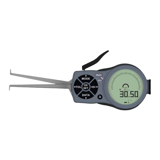
Page 6: Functions And Description
Functions and description Pos. Description Moveable measuring arm Fixed measuring arm Measuring contact Measuring contact Operating lever LCD display Housing Operating keys Interface port Battery cover Fastening screws... - Page 7 Pos. Description LCD – Display Numerical display Scale description Analog display Measuring programs (footer): <0> - Relative mode is activated: 0-Preset with setting gage MIN - program is activated: Determination of the minimum measured value MAX - program is activated: Determination of the maximum measured value HOLD - program is activated: Freezing the currently displayed measured value Pointer Scale interval...
-
Page 8: Preparing To Use The Gage / Changing The Battery
Preparing to use the gage / Changing the battery For the initial use the batteries provided have to be inserted. To open the battery cover 10 loosen the screws 11 by using the screwdriver provided and insert the batteries (2x AAA). Close the battery cover 10 after changing the batteries and tighten the screws 11. -
Page 9: General Advice On Measuring With The Caliper Gage
General advice on measuring with the caliper gage Please be careful with the measuring contacts (3+4) and the movable operating lever 5 and try to manage the gage in measuring position without touching the workpiece. Hold the gage loose during measurement and release the operating lever 5. To determine the correct measuring value, please pivot or displace the gage and read from the display the minimum or maximum deflection of the pointer. -
Page 10: Handling For Dynamic Measurements
Handling for dynamic measurements. Notes on determining the correct measured values in the MIN / MAX / HOLD programs Important: Determination of the minimum measuring value via The measuring axis must pivoting the gage (optimal measurement) be in vertical position to the measuring surface! Measuring value Measuring value... -
Page 11: Program: Absolut/Relativ, Min/Max/Hold
Program: Absolut/Relativ, MIN/MAX/HOLD Initial State. The initial state is a prerequisite for the functioning of all the programs and setting options described. Absolute and Relative Mode. Switching from "Absolute Mode" to "Relative Mode" If the „Absolute - Mode“ is activated measurements will be made with reference to the zero point. -
Page 12: Program Tolerance (Tol)
Program Tolerance (TOL) Aktiviation and Deaktivation the Tolerance function The TOL-Program is an assistance for checking tolerances during measurements. Tolerance field marks 19 and the tolerance display, LED signal (red/green) 18 are activated. The red LED lights up for parts exceeding or falling below the tolerance range (rejected parts). The green LED lights up for parts within the tolerance (good part). -
Page 13: Key Lock. Deactivation Of The Key Lock
Key Lock. Deactivation of the key lock. (Key lock reactivates after 20 seconds!) 1 sec. Data Logger (D-LOG). Use Storage of measured values in the internal memory of the device Back Button. One-step jump back... -
Page 14: Setup-Menu
SETUP Menu 12.1 Accessing the setup menu 12.2 Switch between menu items and selection 12.3 Zero Point Correction (OFFSET). Setting the offset value... -
Page 15: Tolerance Program (Tol). Setting The Tolerance Limits
12.4 Tolerance Program (TOL). Setting the tolerance limits 12.4.1 Selecting the tolerance range 12.4.2 Setting the lower tolerance limit (TOL LO) 12.4.3 Setting the upper tolerance limit (TOL UP) 12.5 Switching MM/INCH (UNIT). Selection of the unit of measurement... -
Page 16: Choice Of Scale Division Value (Scale)
12.6 Choice of Scale Division Value (SCALE). Selection of the scale resolution 12.7 Auto-Power-OFF (A-OFF). Selection of the time after which the device switches to standby 12.8 Data Logger (D-LOG) 12.8.1 ON Activating the data logger... - Page 17 12.8.2 PRINT Printout of the saved measurement values 12.8.3 D-OUT Transferring the measurement values to connected peripherals 12.8.4 RESET Resetting the D-LOG memory 12.8.5 OFF Deactivating the data logger...
-
Page 18: Factory Settings (Reset)
ERR 06 – Tolerance limit outside the permissible range • ERR 07 – OFFSET outside the permissible range The device must be sent to the service centre of Mahr to correct this error • ERR 08 – Reference point in "Relative Mode" outside the display range •... -
Page 19: Accessories
Accessories Pos. no. Order no. Description Interface Adapter 4495079 USB - V2.0 data cable, incl. interface adapter (1) 4495083 DIGIMATIC - V2.0 data cable, incl. interface adapter (1) 4495036 USB Bluetooth 4.0 dongle, incl. interface adapter (1)
Need help?
Do you have a question about the Marameter 838 EI and is the answer not in the manual?
Questions and answers