Trox Technik FKRS-EU Installation And Operating Manual
Fire damper
Hide thumbs
Also See for FKRS-EU:
- Installation and operating manual (263 pages) ,
- Supplementary installation manual (24 pages) ,
- Installation and operating manual (107 pages)

Related Manuals for Trox Technik FKRS-EU


Summary of Contents for Trox Technik FKRS-EU
- Page 1 Installation and operating manual GB/en Fire damper Type FKRS-EU according to Declaration of Performance DoP / FKRS-EU / DE / 004 Read the instructions prior to performing any task!
- Page 2 TROX GmbH Heinrich-Trox-Platz 47504 Neukirchen-Vluyn, Germany Germany Phone: +49 (0) 2845 2020 Fax: +49 (0) 2845 202-265 E-mail: trox@trox.de Internet: http://www.troxtechnik.com Translation of the original M375EE7, 5, GB/en 06/2020 © 2020 Fire damper Type FKRS-EU...
- Page 3 To ensure that your request is processed as quickly as possible, please keep the following information ready: Product name TROX order number Delivery date Brief description of the fault Online www.troxtechnik.com Phone +49 2845 202-400 Fire damper Type FKRS-EU...
- Page 4 Warning – danger zone. NOTICE! Potentially hazardous situation which, if not avoided, may result in property damage. ENVIRONMENT! Environmental pollution hazard. Tips and recommendations Useful tips and recommendations as well as informa- tion for efficient and fault-free operation. Fire damper Type FKRS-EU...
-
Page 5: Table Of Contents
5.6.3 Installation remote from lightweight parti- duct smoke detector........16 tion walls with mineral wool....97 4.4 FKRS-EU with fusible link and cover grille 5.6.4 Dry mortarless installation with fire batt.. 99 used as an air transfer unit......17 5.7 Solid wood walls........106 Installation............ - Page 6 8.3 Functional test with automatic control unit............163 Commissioning..........164 Maintenance........... 165 10.1 General..........165 10.2 Replacing the fusible link....... 166 10.3 Inspection, maintenance and repair measures..........167 Decommissioning, removal and disposal... 169 Explanation............ 170 Index............... 174 Fire damper Type FKRS-EU...
-
Page 7: Safety
Operation of the fire dampers is allowed only in compliance with installation regulations and the technical data in this installation and operating manual. Modifying the fire damper or using replacement parts that have not been approved by TROX is not permitted. Fire damper Type FKRS-EU... -
Page 8: Qualified Staff
Specialist personnel are individuals who have sufficient professional or technical training, knowledge and actual experience to enable them to carry out their assigned duties, understand any potential hazards related to the work under consideration, and recognise and avoid any risks involved. Fire damper Type FKRS-EU... -
Page 9: Technical Data
2006/42/EG - Machinery Directive Declaration of performance DoP / FKRS-EU / DE / 004 Temperatures may differ for units with attachments. Details for Condensation and the intake of humid fresh air have to be avoided as other applications are available on request. - Page 10 Ä Chapter 5.1 ‘Installation situations’ Notified body vary The last two digits of the year in which the CE on page 18 marking was affixed Type Year of manufacture Order number Fire damper Type FKRS-EU...
-
Page 11: Fkrs-Eu With Fusible Link
Technical data FKRS-EU with fusible link 2.2 FKRS-EU with fusible link Dimensions and weight Fig. 2: FKRS-EU with fusible link Keep clear to provide access for operation A Installation side B Operating side Connecting cable length / cross section 1 m / 3 × 0.34 mm²... -
Page 12: Fkrs-Eu With Spring Return Actuator
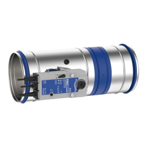
Fig. 3: FKRS-EU with Belimo spring return actuator Keep clear to provide access for operation A Installation side B Operating side Weight of FKRS-EU with fusible link + approx. 1 kg, see table Ä 11. Spring return actuator BFL... - Page 13 Fig. 4: FKRS-EU with Siemens spring return actuator Keep clear to provide access for operation A Installation side B Operating side Ä 11. Weight of FKRS-EU with fusible link + approx. 1 kg, see table Spring return actuator GRA... Construction 326.1E 126.1E...
-
Page 14: Transport And Storage
Do not expose the unit to the effects of weather (not even in its packaging). Do not store the unit below -40 °C or above 50 °C. Packaging Properly dispose of packaging material. Fire damper Type FKRS-EU... -
Page 15: Parts And Function
To ensure proper functioning of the fire damper, a test Ä 160 can be carried out. 4.1 FKRS-EU with fusible link Fig. 6: FKRS-EU with spring return actuator Casing Damper blade with seal Travel stop for CLOSED position Inspection access (12 mm) Lip seal 10.1... -
Page 16: Fkrs-Eu With Spring Return Actuator And Duct Smoke Detector
The duct smoke detector must be installed in a rec- tangular duct at the top by the others, see Fig. 8. Fig. 7: FKRS-EU with spring return actuator and duct smoke detector Casing Damper blade with seal Travel stop for CLOSED position... -
Page 17: Fkrs-Eu With Fusible Link And Cover Grille Used As An Air Transfer Unit
FKRS-EU with fusible link and cover grille used ... 4.4 FKRS-EU with fusible link and cover grille used as an air transfer unit Fig. 10: FKRS-EU with fusible link and cover grille used as an air transfer unit Casing Damper blade with seal... -
Page 18: Installation
The class of performance depends on the installation details N = Mortar-based installation E = Installation kit Thickness increased near the installation opening W = Fire batt Cadolto system E = Dry mortarless installation Depending on local conditions Fire damper Type FKRS-EU... - Page 19 N = Mortar-based installation The class of performance depends on the installation details E = Installation kit Thickness increased near the installation opening W = Fire batt Cadolto system E = Dry mortarless installation Depending on local conditions Fire damper Type FKRS-EU...
- Page 20 N = Mortar-based installation The class of performance depends on the installation details E = Installation kit Thickness increased near the installation opening W = Fire batt Cadolto system E = Dry mortarless installation Depending on local conditions Fire damper Type FKRS-EU...
- Page 21 The class of performance depends on the installation details N = Mortar-based installation E = Installation kit Thickness increased near the installation opening W = Fire batt Cadolto system E = Dry mortarless installation Depending on local conditions Fire damper Type FKRS-EU...
-
Page 22: Safety Notes Regarding Installation
Sharp edges, sharp corners and thin sheet metal requirements for corrosion protection. parts may cause cuts or grazes. When installing the FKRS-EU, the statics of the sup- porting construction (wall / ceiling) must be ensured –... - Page 23 The interior of the fire damper must be accessible for maintenance work and cleaning. For this pur- pose, Type FKRS-EU fire dampers have an inspec- tion access that is closed with a rubber stopper Ä 15. Depending on the installation configuration it may be necessary to provide additional inspection access points in the connecting ducts.
- Page 24 (deviations on request, independent of the installation position of the fire damper). Fig. 13: Any installation position (0 – 360°), duct smoke detector always at top Keep clear to provide access for operation Fire damper Type FKRS-EU...
- Page 25 See "Installation openings" table under the respective installation details Solid wall only Installation into separate installation openings With shortened cover plate Minimum distance depending on fire resistance duration and supporting construction. Distance between installation block(s) Supporting construction, see Ä 26 Fire damper Type FKRS-EU...
- Page 26 E, F E, F hollow stone ceiling, composite ceiling, ribbed ceiling Lightweight ceiling (Cadolto system) A, B, D – F Solid wood ceiling A, B, D – F Wooden beam ceiling A, B, D – F Fire damper Type FKRS-EU...
- Page 27 When you use installation kit WE / WE2, the following materials are acceptable for the cladding of fire dampers and ducts: Promatect® LS35 Promatect® L500 Promatect® AD40 Paroc mineral wool Paroc Hvac Fire Mat 80BLC (80 kg/m³) Fire damper Type FKRS-EU...
- Page 28 The distance from the operating side spigot to the wall has to be 215 mm for installation into fire batt systems. Fire batt systems consist of two layers of mineral wool slabs, gross density ≥ 140 kg/m³. Fire damper Type FKRS-EU...
- Page 29 PYRO-SAFE Flammotect Combi S90 Fire-resistant sealant AGI Flammotect COMBI S90 Fire batt system B max. H max. [mm] [mm] ≤ 3750 ≤ 1840 Promat ® ≤ 3000 ≤ 2115 Hilti ≤ 1900 ≤ 1400 Hensel Fire damper Type FKRS-EU...
- Page 30 Installation General installation information Installation into combined penetration seal FKRS-EU with ablative coating around the perim- Mixed installation of fire dampers FK-EU and FKRS- eter, thickness = min. 2.5 mm EU together with cables and tubes in a fire batt Alternatively: system: Hilti-CFS-CT, CP 670 and CP 673.
- Page 31 Ä 154 Requirements for wall and ceiling systems FKRS-EU fire dampers must be installed in wall and ceiling systems if these walls and ceiling slabs have been erected in compliance with the relevant regula- tions and according to the manufacturers' instructions, Fig.
- Page 32 If reinforcing boards are required, they must be screwed to the metal support structure at intervals of approx. 100 mm. Fig. 20: Distance from the FKRS-EU to other TROX fire dampers in mortar-based installation Fire damper Type FKRS-EU...
- Page 33 outside of the shaft. with supplementary fire-resistant cladding. If reinforcing boards are required, they must be Historical wooden beam ceilings F30. screwed to the metal support structure at intervals of approx. 100 mm. Fire damper Type FKRS-EU...
-
Page 34: Installation Block And Installation Kits
Fig. 21: Overview of installation block and installation kits FKRS-EU 2.11 Installation kit TQ / TQ2 Installation kit WA / WA2 2.12 Installation kit GL / GL2 Installation kit WE / WE2 2.18 Installation block ER with cover plate Fire damper Type FKRS-EU... - Page 35 Fig. 22: Supply package and installation of installation block ER for dry mortarless installation FKRS-EU 2.18 Installation block ER with cover plate Installation opening/cover plate dimensions [mm] Nominal size ÆD1* ☐B Installation opening tolerance ±2 mm * Diameter of the core drill hole in solid walls and ceiling slabs Fire damper Type FKRS-EU...
- Page 36 Half-shell 1 Intumescent seal (2 strips) Installation of installation kit TQ2 Lay half-shells (2.11a) and (2.11b) of the installation kit (2.11) around the FKRS-EU and fix with two brackets (2.11c) (installation position of the FKRS-EU as required). Affix intumescent seal (2.11d).
- Page 37 Half-shell 1 with Kerafix sealing tape Installation of installation kit WA2 Lay half-shells (2.5a) and (2.5b) of the installation kit (2.5) around the FKRS-EU and fix with two brackets (2.5c) (installation position of the FKRS-EU as required). Fire damper Type FKRS-EU...
- Page 38 Half-shell 2 Installation of installation kit WE2 Lay half-shells (2.6a) and (2.6b) of the installation kit (2.6) around the FKRS-EU and fix with two brackets (2.6c) (installation position of the FKRS-EU as required). On the rear of the installation kit (2.6), fix the sheet metal cover plate (2.6d) with 4 dry wall screws (2.6e).
- Page 39 Half-shell 1 Bracket Installation of installation kit GL2 Lay half-shells (2.12a) and (2.12b) of the installation kit (2.12) around the FKRS-EU and fix with two brackets (2.12c) (installation position of the FKRS-EU as required). Fix bracket (2.12d). Fire damper Type FKRS-EU...
-
Page 40: Solid Walls
Fig. 27: Solid walls – arrangement / distances, side by side arrangement also applies to arrangement under one another FKRS-EU Perimeter gap, see Ä 27 Ä 25 Solid wall Distance between the fire dampers, see Additional requirements: solid walls Solid wall Ä 32 Ä 25 Distances and installation orientations, see Fire damper Type FKRS-EU... -
Page 41: Mortar-Based Installation
FKRS-EU Up to EI 120 S for s2 = 40 – 225 mm Mortar Up to EI 90 S for s2 = 10 – 225 mm Solid wall Fire damper Type FKRS-EU... - Page 42 Installation Solid walls > Mortar-based installation Fig. 30: Mortar-based installation into a solid wall, combined, FKRS-EU and FK-EU / FK2-EU FKRS-EU Solid wall FK-EU / FK2-EU up to W × H ≤ 800 × 400 mm Up to EI 90 S Mortar Note: Alternative installation orientations of side-by-side, under or on top of one another possible.
-
Page 43: Mortar-Based Installation - Multiple Occupancy Of An Installation Opening
Additional requirements: mortar-based installation – multiple occupancy of an installation opening Solid wall Ä 32 Size of the installation opening W × H ≤ 1.2 m The number of fire dampers is limited to 10 units in single or double-row arrangement Fire damper Type FKRS-EU... -
Page 44: Mortar-Based Installation With Partial Mortaring
Distance between two FKRS-EU in one installation opening 40 – 225 mm The difficult-to-access installation gap between the FKRS-EU and the wall / ceiling slab must be completely filled in the wall area. Completely close off the remaining gaps »s« (on 2 or 3 sides) with mortar. -
Page 45: Mortar-Based Installation Underneath Flexible Ceiling Joint
If the wall thickness is >115 mm , extend the fire damper on the installation side with an extension piece or a spiral duct. Close off the perimeter gap »s1« with mortar. The mortar bed depth must be at least 100 mm. Fire damper Type FKRS-EU... -
Page 46: Dry Mortarless Installation With Installation Block Er
Fix the cover plate with four threaded rods (push through installation) or with at least four M6 screws. Screw fixings in solid walls must be made using tested anchors appropriate for the construction material of the partic- ular wall. Fire damper Type FKRS-EU... -
Page 47: Dry Mortarless Installation With Installation Kit Tq / Tq2
Fix the cover plate with four threaded rods (push through installation) or with at least four M6 screws. Screw fixings in solid walls must be made using tested anchors appropriate for the construction material of the partic- ular wall. Fire damper Type FKRS-EU... -
Page 48: Dry Mortarless Installation With Installation Kit Wa / Wa2
(M8 or M10). Shorten the mortared-in duct flush with the wall, create a reinforcing board (7.14), compensate for wall unevenness and fix the installation kit by means of push through installation (M8 or M10). Fire damper Type FKRS-EU... -
Page 49: Installation With Installation Kit We / We2
MQZ L13 or equivalent ® Anchor bolt Hilti HUS-6 or equivalent Hexagon nut M10 with washer Sheet steel duct with fire-rated cladding and sus- Up to EI 120 S pension system according to Promat® manual, construction 478, latest edition Fire damper Type FKRS-EU... - Page 50 Mineral wool, ≥ 1000 °C, ≥ 80 kg/m³, or gypsum ® 6.13 Hilti drilled plate, MQZ L13 or equivalent mortar to even out an uneven ceiling Hexagon nut M10 with washer Up to EI 120 S Fire damper Type FKRS-EU...
- Page 51 Mineral wool, ≥ 1000 °C, ≥ 80 kg/m³, or gypsum 6.13 Up to EI 120 S mortar to even out an uneven wall Sheet steel duct with fire-rated cladding and sus- pension system according to Promat® manual, construction 478, latest edition Fire damper Type FKRS-EU...
- Page 52 ≥ 130 mm distance from the fire damper to the wall or ceiling slab ≥ 260 mm distance between two fire dampers Note: For more installation details and for components to be provided by others, see the WE / WE2 installation manual. Fire damper Type FKRS-EU...
-
Page 53: Wall Penetration
Hexagon nut M10 with washer thickness ≤ 20 mm Up to EI 120 S Sheet steel duct with fire-rated cladding and sus- pension system according to Promat® manual, construction 478, latest edition Suspension system (by others) consisting of: Fire damper Type FKRS-EU... - Page 54 Up to EI 120 S Mineral wool (melting point ≥ 1000 °C) or 6.13 gypsum mortar for compensating for uneven ceil- ings Sheet steel duct with fire-rated cladding and sus- pension system according to Promat® manual, construction 478, latest edition Fire damper Type FKRS-EU...
- Page 55 Mineral wool (melting point ≥ 1000 °C) or 6.13 Up to EI 120 S gypsum mortar for compensating for uneven walls Sheet steel duct with fire-rated cladding and sus- pension system according to Promat® manual, construction 478, latest edition Fire damper Type FKRS-EU...
- Page 56 Mineral wool (melting point ≥ 1000 °C) or 6.13 gypsum mortar for compensating for uneven walls and ceilings Sheet steel duct with fire-rated cladding and sus- pension system according to Promat® manual, construction 478, latest edition Fire damper Type FKRS-EU...
- Page 57 ≥ 200 mm distance between two fire dampers (wall penetration through separate wall openings) Note: For more installation details and for components to be provided by others, see the WE / WE2 installation manual. Fire damper Type FKRS-EU...
-
Page 58: Installation Remote From Solid Walls With Mineral Wool
Mineral wool Paroc Hvac Fire Mat 80BLC Sheet steel duct (80 kg/m³) Up to EI 60 S Additional requirements: installation remote from solid walls with mineral wool Solid wall Ä 32 Ä 27 Paroc mineral wool, see Fire damper Type FKRS-EU... -
Page 59: Dry Mortarless Installation With Fire Batt
Fire resistance properties Coating Detail [mm] Installation side Operating side 100 – 200 EI 90 S – – 100 – 315 EI 90 S – 100 – 200 EI 120 S – 100 – 315 EI 120 S Fire damper Type FKRS-EU... - Page 60 Installation near the floor analogous to Ä 61 perimeter, leave out the actuator and release – See table mechanism; inspection openings must remain accessible Note: The fire resistance properties of depend on the nominal width and 6.10*. Fire damper Type FKRS-EU...
- Page 61 Additional requirements: dry mortarless installation with fire batt in solid walls Ä 32 Solid wall Fire batt systems, installation details, distances / dimensions, see Ä 28 f Ä 154 Suspension and fixing, see Fire damper Type FKRS-EU...
-
Page 62: Lightweight Partition Walls And Compart- Ment Walls With Metal Support Structure
Fig. 48: Lightweight partition wall with metal support structure and cladding on both sides Lightweight partition wall / compartment wall / 7.1a UW section, cut in and bent or cut off safety partition wall CW section 7.10 Trim panels according to installation details Fire damper Type FKRS-EU... - Page 63 Opening in the metal support structure (without trim panels: ☐A = ☐A1) Dry wall screw Screw or steel rivet Closed side of metal section must face the instal- Mineral wool (depending on wall construction) lation opening UW section Fire damper Type FKRS-EU...
- Page 64 (without trim panels: ☐A = ☐A1) Screw or steel rivet Mineral wool (depending on wall construction) Closed side of metal section must face the instal- UW section lation opening 7.1a UW section, cut in and bent or cut off Fire damper Type FKRS-EU...
- Page 65 Fig. 50: Metal support structure of compartment wall, single and double stud system Dry wall screw UW section Hexagon head screw M6 CW section Carriage bolt, L ≤ 50 mm, with washer and nut UA section Installation opening according to installation Steel rivet details 5.14 Angle bracket Fire damper Type FKRS-EU...
- Page 66 Option 2: After cladding the wall, create a square wall opening (clear installation opening ≤ 475 mm) – between the regular studs and brace it with a perimeter metal section. Screw metal sections onto both sides over the cladding, spaced approx. 100 mm apart. Fire damper Type FKRS-EU...
-
Page 67: Mortar-Based Installation
Extension piece or duct Mineral wool (depending on wall construction) optional 6.11 Insulating strip (depending on wall construction) – Up to EI 120 S 7.10 Trim panels Up to EI 60 S Fire damper Type FKRS-EU... - Page 68 Solid ceiling slab / solid floor optional Mineral wool (depending on wall construction) Installation near the floor analogous to 6.11 Insulating strip (depending on wall construction) EI 30 S – 7.10 Trim panels EI 30 S – EI 120 S Fire damper Type FKRS-EU...
- Page 69 Up to EI 90 S for s2 = 10 – 225 mm Mineral wool (depending on wall construction) Up to EI 60 S 7.10 Trim panels EI 30 S 7.13 Cladding, fire-resistant, also with sheet steel EI 30 S – EI 120 S insert Fire damper Type FKRS-EU...
- Page 70 Installation Lightweight partition walls and compartment wall... > Mortar-based installation Fig. 54: Mortar-based installation into a lightweight partition wall, FK-EU / FK2-EU and FKRS-EU combined FKRS-EU 7.10 Trim panels FK-EU / FK2-EU up to W × H ≤ 800 × 400 mm according to installation details Fig.
- Page 71 Note: representative illustration. The distance to the ceiling depends on the design of the flexible ceiling joint, the expected ceiling subsidence and the specifications of the wall manufacturer. Additional requirements: mortar-based installation into lightweight partition and compartment walls Lightweight partition wall or compartment wall, see Ä 32 Fire damper Type FKRS-EU...
-
Page 72: Dry Mortarless Installation Without Installation Kit
Make a circular installation opening DN + 6 – 10 mm between two regular studs. Chamfer the outer layer of the cladding all round on both sides and completely fill the surrounding gap on both sides with joint filler to the depth of the cladding. Fire damper Type FKRS-EU... -
Page 73: Dry Mortarless Installation With Installation Kit Tq / Tq2
Mineral wool, ≥ 1000 °C, ≥ 40 kg/m³ wall Mineral wool (depending on wall construction) Extension piece or duct 6.11 Insulating strip (depending on wall construction) optional – Up to EI 120 S 6.13 Mineral wool strips A1, alternatively gypsum mortar UW section Fire damper Type FKRS-EU... - Page 74 Mineral wool, ≥ 1000 °C, ≥ 40 kg/m³ optional Mineral wool (depending on wall construction) Up to EI 120 S UW section Up to EI 60 S – EI 30 S Steel support structure (box section) 7.10 Trim panels (fire-resistant) Fire damper Type FKRS-EU...
- Page 75 Cover plate shortened by others 6.11 Insulating strip (depending on wall construction) 6.13 Mineral wool strips A1, alternatively gypsum – EI 30 S mortar EI 30 S – EI 120 S UW section 7.10 Trim panels (fire-resistant) Fire damper Type FKRS-EU...
- Page 76 Additional requirements: dry mortarless installation with installation kit TQ / TQ2 into lightweight partition walls Lightweight partition wall or compartment wall, see Ä 32 Ä 36 Installation kit TQ / TQ2, see ≥ 200 mm distance between two fire dampers in separate installation openings Fire damper Type FKRS-EU...
-
Page 77: Installation With Installation Kit We / We2
Mineral wool, ≥ 1000 °C, ≥ 80 kg/m³ Up to EI 90 S Sheet steel duct with fire-rated cladding and sus- pension system according to Promat® manual, construction 478, latest edition Suspension system (by others) consisting of: Fire damper Type FKRS-EU... - Page 78 Mineral wool, ≥ 1000 °C or gypsum mortar for 6.13 Up to EI 90 S compensating unevenness Sheet steel duct with fire-rated cladding and sus- pension system according to Promat® manual, construction 478, latest edition Suspension system (by others) consisting of: Fire damper Type FKRS-EU...
- Page 79 Mineral wool, ≥ 1000 °C, ≥ 80 kg/m³ Up to EI 90 S Mineral wool, ≥ 1000 °C or gypsum mortar for 6.13 compensating unevenness Sheet steel duct with fire-rated cladding and sus- pension system according to Promat® manual, construction 478, latest edition Fire damper Type FKRS-EU...
- Page 80 Sheet steel ducts without any openings, with fire-resistant cladding (fittings with cladding according to instruc- tions from Promat®) ≥ 300 mm distance between two fire dampers Note: For more installation details and for components to be provided by others, see the WE / WE2 installation manual. Fire damper Type FKRS-EU...
-
Page 81: Installation Remote From Lightweight Partition And Compartment Walls With Mineral Wool
Acrylic or sealing compound (suitable for fire batt 6.29 Mineral wool Paroc Hvac Fire Mat 80BLC system) (80 kg/m³) Sheet steel duct Up to EI 60 S Additional requirements: installation remote from lightweight partition and compartment walls with mineral wool Fire damper Type FKRS-EU... -
Page 82: Dry Mortarless Installation With Installation Kit Gl / Gl2 During The Wall Construc- Tion
Chamfer the outer layer of the cladding all round on both sides and completely fill the surrounding gap on both sides with filler to the depth of the cladding. Screw metal sections onto both sides over the cladding, spaced approx. 100 mm apart. Fire damper Type FKRS-EU... - Page 83 ≥ 200 mm distance between two fire dampers, distance = 100 mm when installed in the same installation opening Subsidence of the ceiling slab a ≤ 40 mm Installation only under solid ceiling slabs without cavities Note: For installation, follow the supplied installation manual. Fire damper Type FKRS-EU...
-
Page 84: Dry Mortarless Installation With Fire Batt
Installation near the floor analogous to release mechanism; inspection openings must See table Ä 85 – remain accessible 6.20 Sleeve (can be ordered separately) Note: The fire resistance properties of depend on the nominal width and 6.10*. Fire damper Type FKRS-EU... - Page 85 100 – 315 EI 90 S – 100 – 200 EI 120 S – 100 – 315 EI 120 S 100 – 315 EI 60 S – – 100 – 315 EI 30 S – – Fire damper Type FKRS-EU...
- Page 86 Lightweight partition walls and compartment wall... > Dry mortarless installation with fire batt Fig. 70: Dry mortarless installation into a lightweight partition wall, with a fire batt, flange to flange, illustration shows side by side installation (applies also to installation of dampers on top of each other) Fire damper Type FKRS-EU...
- Page 87 EI 120 S – 40 – 600 100 – 315 EI 120 S 40 – 600 100 – 315 EI 60 S – – 10 – 600 100 – 315 EI 30 S – – 10 – 600 Fire damper Type FKRS-EU...
- Page 88 Additional requirements: dry mortarless installation into lightweight partition walls, with fire batt Ä 32 Lightweight partition wall or compartment wall, see Ä 28 f Fire batt systems, installation details, distances / dimensions, see Suspension and fixing, see Ä 154 Fire damper Type FKRS-EU...
-
Page 89: Lightweight Partition Walls With Timber Support Structure
Mineral wool (depending on wall construction) Timber stud, at least 60 × 80 mm ☐A Clear installation opening ☐A1 7.11 Trim panels, double layer, staggered joints Opening in the timber support structure, ☐A1 = ☐A + (4 × trim panels) Fire damper Type FKRS-EU... - Page 90 Mortar-based installation ☐A = ÆDN + 110 mm Dry mortarless installation with installation kit TQ / TQ2 ☐A = ÆDN + 80 – 1200 mm Dry mortarless installation with fire batt Installation opening tolerance ± 2 mm Fire damper Type FKRS-EU...
-
Page 91: Mortar-Based Installation
60 × 60 mm with F60 Up to EI 60 S 7.10 Trim panels (fire-resistant) EI 30 S EI 30 to EI 120 S 7.11 Trim panels, double layer, staggered joints 7.12 Trim panels, wood sheet, at least 600 kg/³ Fire damper Type FKRS-EU... -
Page 92: Fkrs-Eu Mortar
Up to EI 90 S for s2 = 10 – 225 mm 7.11 Trim panels, double layer, staggered joints Up to EI 60 S 7.12 Trim panels, wood sheet, at least 600 kg/³ EI 30 S 7.13a Cladding, fire-resistant EI 30 to EI 120 S Fire damper Type FKRS-EU... - Page 93 EI 30 S ≥ 1000 °C, ≥ 50 kg/m³, or bricks, aerated con- EI 30 to EI 120 S crete, lightweight concrete, reinforced concrete or clay) Half-timbered construction 7.11 Trim panels, fire-resistant, double layer, stag- gered joints Fire damper Type FKRS-EU...
- Page 94 EI 30 to EI 120 S clay) Half-timbered construction 7.11 Trim panels, fire-resistant, double layer, stag- gered joints Additional requirements: lightweight partition walls with timber support structure / half-timbered construc- tion Ä 33 Timber support structure or half-timbered construction, see Fire damper Type FKRS-EU...
-
Page 95: Dry Mortarless Installation With Installation Kit Tq / Tq2
60 × 60 mm with F60 EI 30 S 7.10 Trim panels (fire-resistant) EI 30 to EI 120 S 7.11 Trim panels, double layer, staggered joints 7.12 Trim panels, wood sheet, at least 600 kg/³ Fire damper Type FKRS-EU... - Page 96 / half-timbered construction Timber support structure or half-timbered construction, see Ä 33 Ä 36 Installation kit TQ / TQ2, see ≥ 200 mm distance between two fire dampers in separate installation openings Fire damper Type FKRS-EU...
-
Page 97: Installation Remote From Lightweight Partition Walls With Mineral Wool
(80 kg/m³) Half-timbered construction, cladding on both 6.30 Reinforcing board mineral wool sides Paroc Hvac Fire Mat 80BLC (80 kg/m³), glued all Mineral wool (depending on wall construction) round Sheet steel duct Up to EI 60 S Fire damper Type FKRS-EU... - Page 98 Up to EI 60 S Additional requirements: installation remote from lightweight partition walls with timber support structure with mineral wool Ä 33 Timber support structure or half-timbered construction, see Paroc mineral wool, see Ä 27 Fire damper Type FKRS-EU...
-
Page 99: Dry Mortarless Installation With Fire Batt
6.24 Elastomeric foam (flame-resistant, non-dripping) The following applies in Germany: For notes on Ä 7. the use of elastomeric foams, see Timber stud, min. 60 × 80 mm or min. 60 × 60 mm with F60 Fire damper Type FKRS-EU... - Page 100 100 – 200 EI 120 S – 100 – 315 EI 120 S 100 – 315 EI 60 S – – 100 – 315 EI 30 S – – 100 – 315 EI 30 S – – Fire damper Type FKRS-EU...
- Page 101 Fig. 85: Dry mortarless installation into a lightweight partition wall with timber support structure, with a fire batt, flange to flange, illustration shows side by side installation (applies also to installation of dampers on top of each other) Fire damper Type FKRS-EU...
-
Page 102: Trim Panels, Double Layer, Staggered Joints
40 – 600 100 – 315 EI 60 S – – 10 – 600 100 – 315 EI 30 S – – 10 – 600 100 – 315 EI 30 S – – 10 – 600 Fire damper Type FKRS-EU... - Page 103 100 – 200 EI 90 S – – 100 – 315 EI 90 S – 100 – 200 EI 120 S – 100 – 315 EI 120 S 100 – 315 EI 30 S – – Fire damper Type FKRS-EU...
- Page 104 7.14 Reinforcing board of the same material as the 6.10 Ablative coating around the perimeter, wall 6.19, 6.20 or 6.24 as an alternative d = at least 2.5 mm Installation near the floor analogous to Fire damper Type FKRS-EU...
- Page 105 Additional requirements: dry mortarless installation with fire batt into lightweight partition walls with timber support structure Timber support structure or half-timbered construction, see Ä 33 Ä 28 f Fire batt systems, installation details, distances / dimensions, see Suspension and fixing, see Ä 154 Fire damper Type FKRS-EU...
-
Page 106: Solid Wood Walls
Mortar-based installation ☐A = ÆDN + 110 mm Dry mortarless installation with installation kit TQ / TQ2 ☐A = ÆDN + 80 – 1200 mm Dry mortarless installation with fire batt Installation opening tolerance ± 2 mm Fire damper Type FKRS-EU... -
Page 107: Mortar-Based Installation
Solid wood wall / CLT wall (required if W < 100 mm) Solid ceiling slab / solid floor optional 5.13 Wood screw or pin Installation near the floor analogous to 7.10 Trim panels Up to EI 90 S – Fire damper Type FKRS-EU... - Page 108 Wood screw or pin Installation near the floor analogous to 7.10 Trim panels Up to EI 90 S – Additional requirements: mortar-based installation into solid wood walls Solid wood wall or CLT wall Ä 33 Fire damper Type FKRS-EU...
-
Page 109: Dry Mortarless Installation With Installation Kit Tq / Tq2
Additional requirements: dry mortarless installation with installation kit TQ / TQ2 into solid wood walls Ä 33 Solid wood wall or CLT wall Installation kit TQ / TQ2, see Ä 36 ≥ 200 mm distance between two fire dampers in separate installation openings Fire damper Type FKRS-EU... -
Page 110: Installation Remote From Solid Wood Walls With Mineral Wool
Paroc Hvac Fire Mat 80BLC (80 kg/m³), glued all round Additional requirements: installation remote from solid wood walls with mineral wool Ä 33 Solid wood wall or CLT wall Ä 27 Paroc mineral wool, see Fire damper Type FKRS-EU... -
Page 111: Dry Mortarless Installation With Fire Batt
6.20 Sleeve (can be ordered separately) 6.24 Elastomeric foam (flame-resistant, non-dripping) The following applies in Germany: For notes on the use of elastomeric foams, see Ä 7. Fire damper Type FKRS-EU... - Page 112 Solid wood wall or CLT wall Fire batt systems, installation details, distances / dimensions, see Ä 28 f Ä 154 Suspension and fixing, see ≥ 200 mm distance between two fire dampers in separate installation openings Fire damper Type FKRS-EU...
-
Page 113: Shaft Walls With Metal Support Structure
Installation Shaft walls with metal support structure > Dry mortarless installation with fire batt 5.8 Shaft walls with metal support structure Fig. 96: Shaft walls with metal support structure and cladding on one side Fire damper Type FKRS-EU... - Page 114 Mortar-based installation ☐A = ÆDN + 110 mm Dry mortarless installation with installation kit TQ / TQ2 ÆDN + approx. 5 mm Dry mortarless installation with installation kit WA / WA2 Installation opening tolerance ± 2 mm Fire damper Type FKRS-EU...
-
Page 115: Mortar-Based Installation
Installation near the floor analogous to Mineral wool (depending on wall construction) – Up to EI 90 S UW section – Up to EI 90 S Steel support structure (box section) EI 30 S – EI 90 S 7.10 Trim panels Fire damper Type FKRS-EU... - Page 116 7.14 Reinforcing board of the same material as the Dry wall screw wall Mineral wool (depending on wall construction) optional UW section – Up to EI 90 S Steel support structure (box section) Fire damper Type FKRS-EU...
- Page 117 Wall without adequate fire resistance rating optional Solid ceiling slab / solid floor Installation near the floor analogous to Dry wall screw EI 30 S – UW section EI 30 S – EI 90 S 7.10 Trim panels Fire damper Type FKRS-EU...
- Page 118 Installation Shaft walls with metal support structure > Mortar-based installation Fig. 100: Mortar-based installation into a shaft wall, FKA2-EU and FKRS-EU combined FKRS-EU 7.13 Cladding, two layers FK-EU / FK2-EU up to W × H ≤ 800 × 400 mm 7.14...
-
Page 119: Dry Mortarless Installation With Installation Kit Tq / Tq2
Additional requirements: dry mortarless installation with installation kit TQ / TQ2 into shaft walls with metal support structure Shaft wall Ä 33 Ä 36 Installation kit TQ / TQ2, see ≥ 200 mm distance between two fire dampers in separate installation openings Fire damper Type FKRS-EU... -
Page 120: Dry Mortarless Installation With Installation Kit Wa / Wa2
Create a reinforcing board (7.14) and fix it to the installation kit. Create Promatect strips (8.3). Push the fire damper into the wall opening and fix it with threaded rods (5.4) and Promatect strips (8.3). Apply fire-resistant cladding (7.19). Fire damper Type FKRS-EU... -
Page 121: Shaft Walls Without Metal Support Structure
Nominal size ☐A = ÆDN + 110 mm Dry mortarless installation with installation kit TQ / TQ2 ÆDN + approx. 5 mm Dry mortarless installation with installation kit WA / WA2 Installation opening tolerance ± 2 mm Fire damper Type FKRS-EU... -
Page 122: Dry Mortarless Installation With Installation Kit Tq / Tq2
Ä 36 Installation kit TQ / TQ2, see ≥ 200 mm distance between two fire dampers in separate installation openings Approx. 100 mm distance from the fire damper to load-bearing / adjacent structural elements Fire damper Type FKRS-EU... -
Page 123: Dry Mortarless Installation With Installation Kit Wa / Wa2
Create a reinforcing board (7.14) and fix it to the installation kit. Create Promatect strips (8.3). Push the fire damper into the wall opening and fix it with threaded rods (5.4) and Promatect strips (8.3). Apply fire-resistant cladding (7.19). Fire damper Type FKRS-EU... -
Page 124: Sandwich Panel Walls
Extension piece or duct perimeter, 6.19, 6.20 or 6.24 as an alternative Leave out the actuator and release mechanisms; Up to EI 90 S inspection openings must be accessible 6.20 Sleeve (can be ordered separately) Fire damper Type FKRS-EU... - Page 125 Additional requirements: dry mortarless installation into sandwich panel walls Sandwich panel wall, see Ä 33 Ä 31 Installation into fire protection block bulkhead, see Suspension and fixing, see Ä 154 Note: For installation, follow the supplied installation manual. Fire damper Type FKRS-EU...
-
Page 126: Solid Ceiling Slabs
Fig. 108: Solid ceilings – arrangement / distances, side-by-side arrangement by way of example Ä 27 FKRS-EU Perimeter gap, see Solid ceiling slab Distance between the fire dampers, see Ä 25 Additional requirements: solid ceiling slabs Ä 33 Solid wall Ä 25 Distances and installation orientations, see Fire damper Type FKRS-EU... -
Page 127: Mortar-Based Installation
Fig. 109: Mortar-based installation into a solid ceiling slab with blending into the screed, suspended or upright FKRS-EU 6.22 Screed Mortar 6.23 Footfall sound insulation Reinforced concrete – Up to EI 120 S Solid ceiling slab Fire damper Type FKRS-EU... - Page 128 ≥ 45 mm distance between two fire dampers Structural and fire resistance properties of the ceiling construction, including the attachment to the concrete or any required reinforcement, have to be evaluated and ensured by others. Fire damper Type FKRS-EU...
-
Page 129: Mortar-Based Installation Into A Concrete Base
Fig. 111: Mortar-based installation with concrete base into a solid ceiling slab, upright Steel fabric, Æ ≥ 8 mm, mesh aperture 150 mm, FKRS-EU 5.22 Concrete base or equivalent, for number of fixing points: 4 Solid ceiling slab Extension piece or duct Up to EI 120 S Fire damper Type FKRS-EU... - Page 130 Steel fabric, Æ ≥ 8 mm, mesh aperture 150 mm, FKRS-EU 5.22 Concrete base, A × B ≤ 1.2 m² or equivalent, for number of fixing points see Ä 132 Solid ceiling slab table Extension piece or duct Up to EI 90 S Fire damper Type FKRS-EU...
- Page 131 Installation Solid ceiling slabs > Mortar-based installation into a concrete base Fig. 113: Mortar-based installation with concrete base into a solid ceiling slab, upright, combined, FKRS-EU and FK- EU / FK2-EU Steel fabric, Æ ≥ 8 mm, mesh aperture 150 mm, FKRS-EU 5.22...
- Page 132 Concrete bases H ≤ 150 mm do not require reinforcement ≥ 45 – 225 mm distance between two fire dampers. ≥ 200 mm distance between two pairs of FKRS-EU. ≥ 50 – 225 mm distance to fire dampers FK-EU / FK2-EU ...
-
Page 133: Mortar-Based Installation Into Hollow Stone Ceilings
≥ 45 mm distance between two fire dampers Structural and fire resistance properties of the ceiling construction, including the attachment to the concrete or any required reinforcement, have to be evaluated and ensured by others. Fire damper Type FKRS-EU... -
Page 134: Mortar-Based Installation Into Hollow Chamber Ceilings
(in relation to the depth) by at least 100 mm. Structural and fire resistance properties of the ceiling construction, including the attachment to the concrete or any required reinforcement, have to be evaluated and ensured by others. Fire damper Type FKRS-EU... -
Page 135: Mortar-Based Installation Into Ribbed Ceilings
≥ 45 mm distance between two fire dampers Structural and fire resistance properties of the ceiling construction, including the attachment to the concrete or any required reinforcement, have to be evaluated and ensured by others. Fire damper Type FKRS-EU... -
Page 136: Mortar-Based Installation Into Composite Ceilings
≥ 45 mm distance between two fire dampers Structural and fire resistance properties of the ceiling construction, including the attachment to the concrete or any required reinforcement, have to be evaluated and ensured by others. Fire damper Type FKRS-EU... -
Page 137: Mortar-Based Installation In Conjunction With Wooden Beam Ceilings
≥ 45 mm distance between two fire dampers Structural and fire resistance properties of the ceiling construction, including the attachment to the concrete or any required reinforcement, have to be evaluated and ensured by others. Fire damper Type FKRS-EU... -
Page 138: Mortar-Based Installation In Conjunction With Solid Wood Ceilings
≥ 45 mm distance between two fire dampers Structural and fire resistance properties of the ceiling construction, including the attachment to the concrete or any required reinforcement, have to be evaluated and ensured by others. Fire damper Type FKRS-EU... -
Page 139: Mortar-Based Installation In Conjunction With Lightweight Ceilings
≥ 45 mm distance between two fire dampers Structural and fire resistance properties of the ceiling construction, including the attachment to the concrete or any required reinforcement, have to be evaluated and ensured by others. Fire damper Type FKRS-EU... -
Page 140: Dry Mortarless Installation With Installation Block Er
Fix the cover plate with four threaded rods (push through installation) or with at least four M6 screws. For solid walls and solid ceiling slabs, suitable steel anchors with building inspectorate approval must be used. Fire damper Type FKRS-EU... -
Page 141: Installation With Installation Kit We / We2 Remote From Solid Ceiling Slabs
MQ 41 × 3 mm or equivalent ® Hilti Anchor bolt Hilti HUS-6 or equivalent Steel angle section 40 × 40 × 1.5 mm ® Hilti drilled plate, MQZ L13 or equivalent Hexagon nut M10 with washer Up to EI 90 S Fire damper Type FKRS-EU... - Page 142 Solid ceiling slab Hexagon nut M10 with washer Mineral wool, ≥ 1000 °C, ≥ 80 kg/m³ Wall penetration according to Promat® manual, Sheet steel duct with fire-rated cladding construction 478, latest edition Up to EI 90 S Fire damper Type FKRS-EU...
- Page 143 ≥ 130 mm distance from the fire damper to the wall or ceiling slab ≥ 260 mm distance between two fire dampers Note: For more installation details and for components to be provided by others, see the WE / WE2 installation manual. Fire damper Type FKRS-EU...
-
Page 144: Dry Mortarless Installation With Fire Batt
6.19, 6.20 or 6.24 as an alternative – See table Ä 145 6.19 Mineral wool > 1000 °C, > 80 kg/m³, thickness = 20 mm, panel material around the perimeter, leave out the actuator and release mechanism; inspection openings must remain accessible Fire damper Type FKRS-EU... - Page 145 ≥ 75 mm distance from fire damper to load-bearing structural elements ≥ 200 mm distance between two fire dampers in separate installation openings Fire batt systems, installation details, distances / dimensions, see Ä 28 Ä 154 Suspension and fixing, see Fire damper Type FKRS-EU...
-
Page 146: Solid Wood Ceilings
≥ 200 mm distance between two fire dampers in separate installation openings Structural and fire resistance properties of the ceiling construction, including the attachment to the concrete or any required reinforcement, have to be evaluated and ensured by others. Fire damper Type FKRS-EU... -
Page 147: Dry Mortarless Installation With Installation Kit Tq / Tq2 Into Solid Wood Ceilings
≥ 200 mm distance between two fire dampers in separate installation openings Structural and fire resistance properties of the ceiling construction, including the attachment to the concrete or any required reinforcement, have to be evaluated and ensured by others. Fire damper Type FKRS-EU... -
Page 148: Wooden Beam Ceilings
Wood sheet, at least 600 kg/³ Up to EI 60 S Wooden beam / gluelam min. 100 × 80 mm 7.16 EI 30 S (reduce distances between wooden beams to the size of the installation opening) Fire damper Type FKRS-EU... - Page 149 ≥ 200 mm distance between two fire dampers in separate installation openings Structural and fire resistance properties of the ceiling construction, including the attachment to the concrete or any required reinforcement, have to be evaluated and ensured by others. Fire damper Type FKRS-EU...
-
Page 150: Dry Mortarless Installation With Installa- Tion Kit Tq / Tq2 Into Wooden Beam Ceilings
Mineral wool fill if required 7.11 Trim panel, same construction as 7.19 7.19 Fire-resistant cladding (ceiling-dependent) 7.15 Wood sheet, at least 600 kg/³ Up to EI 90 S Up to EI 60 S EI 30 S Fire damper Type FKRS-EU... - Page 151 ≥ 200 mm distance between two fire dampers in separate installation openings Structural and fire resistance properties of the ceiling construction, including the attachment to the concrete or any required reinforcement, have to be evaluated and ensured by others. Fire damper Type FKRS-EU...
-
Page 152: Mortar-Based Installation Into Historical Wooden Beam Ceilings
Wooden floorboard / floor covering* Mortar 7.16 Wooden beam Concrete Extension piece or duct 6.26 Plaster* Illustration representative, other ceiling construc- 6.28 Ceiling fill* tions possible according to local conditions and 7.10 Trim panels ceiling manufacturers EI 30 S Fire damper Type FKRS-EU... - Page 153 ≥ 200 mm distance between two fire dampers in separate installation openings Structural and fire resistance properties of the ceiling construction, including the attachment to the mortar/ concrete or any required reinforcement, have to be evaluated and ensured by others. Fire damper Type FKRS-EU...
-
Page 154: Fixing The Fire Damper
(according to Promat® work sheet 478, for example). Load the suspension system only with the weight of the fire damper, ducting must be suspended separately. For weights [kg] of FKRS-EU fire dampers see Ä 11. In addition to the fixing systems described in this manual, you may also use fixing systems that have Fig. - Page 155 Danger of falling off! Do not step onto the fire batt! The fire batt cannot carry any loads. Adequate means, e.g. a permanent barrier, must be installed to prevent people from stepping onto the fire batt. Fire damper Type FKRS-EU...
- Page 156 Anchor bolt Hilti HUS-6 or equivalent 5.19 L-bracket according to EN 10056-1, 20 × 20 × 3 mm galvanised, painted or similar. 5.20 L-bracket according to EN 10056-1, 35 × 35 × 4 mm galvanised, painted or similar. Fire damper Type FKRS-EU...
-
Page 157: Fire Damper Remote From Walls And Ceilings
Installation Fixing the fire damper > Fire damper remote from walls and ceilings 5.14.3 Fire damper remote from walls and ceilings Fig. 139: FKRS-EU in a cladded duct FKRS-EU Threaded rod M10 ® mounting rail MQ 41 × 3 mm or equivalent... -
Page 158: Accessories
Nominal size [mm] x [mm] y [mm] -220 -208 -67.5 -195 -190 -180 -170 Fig. 141: FKRS-EU with flexible connectors -158 FKRS-EU -145 9.1 Flexible connector -130 -113 27.5 Cover grille Cover grilles are used on non-ducted ends of fire dampers. -
Page 159: Electrical Connection
Note: For wiring explosion-proof spring return actuator structure (wall or ceiling slab). They must not be see "Supplementary operating manual for explosion- fixed to the fire damper. proof fire dampers Type FKRS-EU". Actuators with 24 V AC/DC Type of Limit... -
Page 160: Functional Test
The handle (1.6) swivels automatically in the direction of the arrow. The damper blade is closed and the handle (1.6) shows that the damper blade is Fig. 147: Damper blade position indicator closed. Damper blade is closed Damper blade is open Fire damper Type FKRS-EU... -
Page 161: Fire Damper With Spring Return Actuator
Release the push button (1). ð Power is supplied again, and the damper Fig. 149: Damper blade position indicator blade opens. Damper blade is closed Check if the damper blade is OPEN, check run Damper blade is open time. Fire damper Type FKRS-EU... - Page 162 Turn the crank handle in the direction of the arrow (2) to just short of the travel stop and hold it. Set the interlock (3) to "Lock " ð The damper blade remains in the OPEN posi- tion. Remove the crank handle. Fire damper Type FKRS-EU...
-
Page 163: Functional Test With Automatic Control Unit
They may also indicate the need for additional measures which help to maintain the sys- tem's function, e.g. removing heavy contamination (dust in extract air systems). Fire damper Type FKRS-EU... -
Page 164: Commissioning
CLOSED fire dampers Fire dampers which close while the ventilation and air conditioning system is running must be inspected before they are opened again in order to ensure their Ä ‘Inspection’ on page 165. correct function Fire damper Type FKRS-EU... -
Page 165: Maintenance
For safety reasons, repair work must only be carried out by expert qualified personnel or the manufacturer. Only original replacement parts are to be used. A functional Ä 160 is required after any repair work. test Fire damper Type FKRS-EU... -
Page 166: Replacing The Fusible Link
While doing so, slightly press down the fasten with screws (10.17). tab (1.6) of the handle. ð Carry out functional test. Fig. 154: Replacing the fusible link 10.15 Fusible link holder 10.18 Fusible link 10.20 Spring Fire damper Type FKRS-EU... -
Page 167: Inspection, Maintenance And Repair Measures
Function OK Fire damper closes when triggered manually or when smoke is detected Fire damper opens after reset – Determine and eliminate the cause of the fault – Repair or replace duct smoke detector Fire damper Type FKRS-EU... - Page 168 (remote controlled). The system owner can then set the intervals for local tests. C = as required Item to be checked Required condition – Remedial action if necessary Fire damper Type FKRS-EU...
-
Page 169: Decommissioning, Removal And Disposal
Disconnect the wiring. Remove the ducts. Close the damper blade. Remove the fire damper. Disposal For disposal, the fire damper must be disassembled. ENVIRONMENT! Dispose of electronic components according to the local electronic waste regulations. Fire damper Type FKRS-EU... -
Page 170: Explanation
> REI 30 2.17 Hilti CFS-BL fire stop block 2.18 Installation block ER with cover plate 2.19 Joint filler (Promat® filler, Promat® ready-to- use putty; mineral wool > 80 kg / m³, > 1000 °C or mortar) Fire damper Type FKRS-EU... - Page 171 Mineral wool ≥ 1000 °C, ≥ 140 kg/m³ UW section Mineral wool (depending on wall construc- 7.1a UW section, cut and bent tion) / ceiling construction, mineral wool filling CW section (metal support structure) on request Fire damper Type FKRS-EU...
- Page 172 Extension piece or duct Prop Material for extended applications Sheet steel duct with L90 cladding and sus- PROMATECT®-H strip b ≥ 100 mm, pension system according to Promat® d = 10 mm manual, construction 478, latest edition Suspension Fire damper Type FKRS-EU...
- Page 173 Thermoelectric release mechanism with tem- perature sensor 10.14 Thermal release mechanism with fusible link, 72 °C / 95 °C 10.15 Fusible link holder 10.16 Fusible link holder rocker 10.17 Screw 10.18 Fusible link 10.19 Cover 10.20 Spring Fire damper Type FKRS-EU...
-
Page 174: Index
Product sticker............10 Flexible ceiling joint..........18, 45 Flexible connectors..........158 Release mechanism..........15, 17 Functional description........15, 16, 17 Removal..............169 Functional test............160 Repair............... 165 Fusible link........... 15, 17, 166 Ribbed ceilings..........18, 33, 135 Fire damper Type FKRS-EU... - Page 175 Solid wood walls........... 18, 33, 106 Spring return actuator...... 12, 13, 15, 16, 159 Wall mounting............18, 49 Storage............... 14 Wall penetration..........18, 53, 77 Suspension.............. 154 Weights............11, 12, 13 Symbols............... 4 Wooden beam ceilings......18, 33, 137, 148 Fire damper Type FKRS-EU...
- Page 176 Fire damper Type FKRS-EU...
Need help?
Do you have a question about the FKRS-EU and is the answer not in the manual?
Questions and answers