Trox Technik FK2-EU Installation And Operating Manual
Fire damper
Hide thumbs
Also See for FK2-EU:
- Installation and operating manual (260 pages) ,
- Manual (61 pages) ,
- Additional manual (16 pages)

Related Manuals for Trox Technik FK2-EU


Summary of Contents for Trox Technik FK2-EU
- Page 1 Installation and operating manual GB/en Fire damper Type FK2-EU according to Declaration of Performance DoP / FK2-EU / DE / 002 Read the instructions prior to performing any task!
- Page 2 TROX GmbH Heinrich-Trox-Platz 47504 Neukirchen-Vluyn, Germany Germany Phone: +49 (0) 2845 2020 Fax: +49 (0) 2845 202-265 E-mail: trox-de@troxgroup.de Internet: http://www.troxtechnik.com Translation of the original A00000083907, 2, GB/en 11/2020 © 2020 Fire damper Type FK2-EU...
- Page 3 To ensure that your request is processed as quickly as possible, please keep the following information ready: Product name TROX order number Delivery date Brief description of the fault Online www.troxtechnik.com Phone +49 2845 202-400 Fire damper Type FK2-EU...
- Page 4 Warning – danger zone. NOTICE! Potentially hazardous situation which, if not avoided, may result in property damage. ENVIRONMENT! Environmental pollution hazard. Tips and recommendations Useful tips and recommendations as well as informa- tion for efficient and fault-free operation. Fire damper Type FK2-EU...
-
Page 5: Table Of Contents
2.2 FK2-EU with fusible link ......11 5.5.4 Dry mortarless installation with installa- tion kit ES ..........2.3 FK2-EU with spring return actuator ..14 5.5.5 Dry mortarless installation with mineral 2.4 FK2-EU with spring return actuator and wool ............91 duct smoke detector ........ - Page 6 Functional test ..........186 8.1 Fire damper with fusible link ....186 8.1.1 Fusible link – size 1 ......186 8.1.2 Fusible link – size 2 and 3 ....187 8.2 Fire damper with spring return actuator Fire damper Type FK2-EU...
-
Page 7: Safety
TROX is not permitted. If this fire damper is used in Germany: Do not use it in extract air systems in commercial kitchens. Use as air transfer damper only according to gen- eral type approval. Fire damper Type FK2-EU... -
Page 8: Qualified Staff
Specialist personnel are individuals who have sufficient professional or technical training, knowledge and actual experience to enable them to carry out their assigned duties, understand any potential hazards related to the work under consideration, and recognise and avoid any risks involved. Fire damper Type FK2-EU... -
Page 9: Technical Data
Condensation and the intake of humid fresh air have to be avoided as otherwise operation will be impaired or not possible. For explosion-proof constructions of the FK2-EU see the corresponding operating manual. Leakage rate of the fire damper system tested at 300 Pa and 500 Pa negative pressure. - Page 10 Regulated characteristics; the fire resistance class publication depends on the application and may vary Notified body Type The last two digits of the year in which the CE Order number marking was affixed Year of manufacture Fire damper Type FK2-EU...
-
Page 11: Fk2-Eu With Fusible Link
Length of the fire damper (casing length) Installation side Keep clear to provide access for operation Operating side Ä 12 . Weight of FK2-EU with fusible link, see table Sizes 1 to 3, see table Ä 12 . ... - Page 12 Technical data FK2-EU with fusible link Weight [kg] for casing length L = 305 [mm] / L = 500 [mm] B [mm] [mm] 1000 1100 1200 1300 1400 1500 8/11 9/12 10/13 – – – – – – – 8/10 9/12 10/13 11/15 –...
- Page 13 Technical data FK2-EU with fusible link Flange holes Fig. 3: Flange holes L = 305 mm – uneven and even number of holes Fig. 4: Flange holes L = 500 mm – uneven and even number of holes B or H [mm]...
-
Page 14: Fk2-Eu With Spring Return Actuator
Horizontally arranged spring return actuator Operating side Ä 12 . Weight of FK2-EU with fusible link + approx. 1 kg (BFL... and BFN...), see table Ä 12 . Sizes 1 to 3 and arrangement of the spring return actuator [A] or [B], see table ... - Page 15 Technical data FK2-EU with spring return actuator Spring return actuator BFL... Construction 230-T TR 24-T-ST TR Supply voltage 230 V AC, 50/60 Hz 24 V AC/DC, 50/60 Hz Functional range 198 – 264 V AC 19.2 – 28.8 V AC 21.6 –...
- Page 16 Technical data FK2-EU with spring return actuator Spring return actuator BFN... Construction 230-T TR 24-T-ST TR Supply voltage 230 V AC, 50/60 Hz 24 V AC/DC, 50/60 Hz Functional range 198 – 264 V AC 19.2 – 28.8 V AC 21.6 –...
- Page 17 1 m, 2 × 0.75 mm² / 1 m, 6 × 0.75 mm² (free of halo- gens) BF actuator optional, weight of FK2-EU with fusible link + approx. 2 kg ¹ Up to 75 °C the safe position will definitely be reached.
- Page 18 Horizontally arranged spring return actuator Operating side Ä 12 . Weight of FK2-EU with fusible link + approx. 1.4 kg (GRA... and GNA...), see table Ä 12 . Sizes 1 to 3 and arrangement of the spring return actuator [A] or [B], see table ...
- Page 19 Technical data FK2-EU with spring return actuator Spring return actuator GRA... Construction 326.1E 126.1E Supply voltage 230 V AC, 50/60 Hz 24 V AC, 50/60 Hz / 24 – 48 V DC Functional range 198 – 264 V AC 19.2 – 28.8 V AC 19.2 –...
- Page 20 Connecting cable Actuator / limit switch 0.9 m, 6 × 0.75 mm² (free of halogens) GGA actuator optional, weight of FK2-EU with fusible link + approx. 2.5 kg *Connecting cable at the bottom FK2-EU with Joventa spring return actuator The FK2-EU can also be supplied with Joventa spring return actuator on request: SFR 2.90 T...
- Page 21 Length of the fire damper (casing length) Installation side Horizontally arranged spring return actuator Operating side Weight of FK2-EU with fusible link + approx. 2.5 kg (BFL... and BFN...), see table Ä 12 . Ä 15 and Ä 17 Technical data for spring return actuator, see table ...
-
Page 22: Fk2-Eu With Fusible Link And Cover Grille
2.5 FK2-EU with fusible link and cover grille used as an air transfer unit Dimensions and weight Fig. 8: FK2-EU with fusible link and cover grille used as an air transfer unit Width of the fire damper (side B) 75 mm size 1... -
Page 23: Fk2-Eu With Spring Return Actuator And
2.6 FK2-EU with spring return actuator and duct smoke detector used as an air transfer damper Dimensions and weight Fig. 9: FK2-EU with spring return actuator and duct smoke detector used as an air transfer damper Width of the fire damper (side B) Vertically arranged spring return actuator... -
Page 24: Supply Package, Transport And Storage
Store the product in a dry place and away from direct sunlight. Do not expose the unit to the effects of weather (not even in its packaging). Do not store the product below -40 °C or above 50 °C. Fire damper Type FK2-EU... -
Page 25: Parts And Function
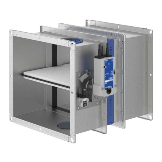
( 95 °C in warm air ventilation systems). If the damper blade closes due to a temperature increase (i.e. in the event of a fire), it must not be reopened. 4.1 FK2-EU with fusible link Fig. 11: FK2-EU with spring return actuator Casing Damper blade Inspection access 10.1... -
Page 26: Fk2-Eu With Spring Return Actuator And Duct Smoke Detector
4.4 FK2-EU with fusible link and cover and duct smoke detector grille used as an air transfer unit Fig. 12: FK2-EU with spring return actuator and duct Fig. 13: FK2-EU with fusible link and cover grille used smoke detector as an air transfer unit Casing... -
Page 27: Fk2-Eu With Spring Return Actuator And
FK2-EU with spring return actuator and duct smok... 4.5 FK2-EU with spring return actuator and duct smoke detector used as an air transfer damper Fig. 14: FK2-EU with spring return actuator and duct smoke detector used as an air transfer damper Casing Damper blade Inspection access 9.10... -
Page 28: Installation
An extension piece may be required N = Mortar-based installation E = Installation kit Gypsum wall boards EN 12859 W = Fire batt Thickness increased near the installation opening E = Dry mortarless installation Cadolto system Depending on local conditions Fire damper Type FK2-EU... - Page 29 An extension piece may be required E = Installation kit Gypsum wall boards EN 12859 W = Fire batt Thickness increased near the installation opening E = Dry mortarless installation Cadolto system Depending on local conditions Fire damper Type FK2-EU...
- Page 30 An extension piece may be required E = Installation kit Gypsum wall boards EN 12859 W = Fire batt Thickness increased near the installation opening E = Dry mortarless installation Cadolto system Depending on local conditions Fire damper Type FK2-EU...
- Page 31 An extension piece may be required E = Installation kit Gypsum wall boards EN 12859 W = Fire batt Thickness increased near the installation opening E = Dry mortarless installation Cadolto system Depending on local conditions Fire damper Type FK2-EU...
- Page 32 An extension piece may be required E = Installation kit Gypsum wall boards EN 12859 W = Fire batt Thickness increased near the installation opening E = Dry mortarless installation Cadolto system Depending on local conditions Fire damper Type FK2-EU...
-
Page 33: Safety Notes Regarding Installation
For this pur- The adhesive tape in the installation area must NOT pose, the type FK2-EU fire damper has two inspec- be removed. Ä 25 . Depending on the installation tion accesses Protect the fire damper from humidity and conden- ... - Page 34 (attachment or by others) on Ä 182 . the installation side, see also extension pieces Fire damper Type FK2-EU...
- Page 35 ≥ 200 mm. The fire damper with assembled duct smoke detector must be installed in a horizontal installation position, duct smoke detector at the top, (deviations on request). Fig. 17: Horizontal installation Fire damper Type FK2-EU...
- Page 36 Solid wood wall / cross-laminated timber wall E, F E, F E, F Shaft wall A – F E, F Solid ceiling slab A, B, D – F E, F In combination with lightweight ceiling A, B, D – F (Cadolto system) Fire damper Type FK2-EU...
- Page 37 Maximum gap widths are based on EN 15882-2. Larger gaps do not have an adverse effect with regard to fire protection and are in our opinion not critical. Fig. 20: FK2-EU with prop FK2-EU 9.3 Prop Fire damper Type FK2-EU...
- Page 38 Promatect® LS35 Promatect® L500 Promatect® AD40 Fig. 21: Installation kit – free space (with normal installa- tion) FK2-EU Installation kit ES Wall Dry wall screw, to be provided by others 5.15 Bracket Fire damper Type FK2-EU...
- Page 39 shortened so as to be flush-mounted in the wall/ ceiling. Alternatively, it is possible to mount the FK2-EU flush in front of a core drill or a circular duct short- ened so as to be flush-mounted in the wall. The movement of the damper blade must not be impaired by this.
- Page 40 (min. M8) or alternatively with threaded rods and push through installation. For additional installation details see corresponding installation situation. Fig. 24: Fire-resistant sealant FK2-EU Coated board system 8.21 Firestop sealant Installation side Operating side Fire damper Type FK2-EU...
- Page 41 PYRO-SAFE Flammotect Combi S90 Fire-resistant sealant AGI Flammotect COMBI S90 Fire batt system B max. H max. [mm] [mm] ≤ 3750 ≤ 1840 Promat ® ≤ 3000 ≤ 2115 Hilti ≤ 1900 ≤ 1400 Hensel Fire damper Type FK2-EU...
- Page 42 11.3 Pipe collar and pipe penetrations is ≥ 50 mm. 11.6 Cable penetration ≥ 50 mm distance from FK2-EU to fire dampers FKRS-EU. If this fire damper is used in Germany: The position of the fire dampers, tubes and cable in ...
- Page 43 100 mm. Installation only permitted in non-load-bearing walls (load-bearing wall constructions on request). Fig. 27: Distance from the FK2-EU to other TROX fire dampers in mortar-based installation Fire damper Type FK2-EU...
- Page 44 Installation is carried out with the actuator on the outside of the shaft. If reinforcing boards are required, they must be screwed to the metal support structure at intervals of approx. 100 mm. Fire damper Type FK2-EU...
-
Page 45: General Installation Information
Fig. 29: Assembly of installation kit ES for dry mortarless installation Installation kit ES 5.19 Connecting clip (8 pieces) B part (2 ×) 2.9.1 6.12 Intumescent seal (4 pieces) H part (2 ×) 2.9.2 Fire damper Type FK2-EU... - Page 46 Screw in the brackets (5.15) for fastening to the wall on the installation kit with dry wall screw (5.1). The number and position of the brackets are dependent on the size and correspond with the drilled holes made in the factory. For subsequent assembly and installation steps see the installation details. Fire damper Type FK2-EU...
- Page 47 Fig. 32: Assembly of installation kit WA / WE for dry mortarless installation H part (2 ×) Installation kit ES 2.9.2 B part (2 ×) 2.9.1 5.19 Connecting clip (4 pieces) Fire damper Type FK2-EU...
- Page 48 ® 5.17 HUS anchor bolt Æ 6 mm (120 mm) Hilti Alternatively, equivalent anchor bolts with suita- bility certificate for fire resistance provided by others, matched to the wall / ceiling slab or push through installation Fire damper Type FK2-EU...
- Page 49 Fix fire damper (1) to sheet steel duct and apply fire-resistant cladding according to the details of the respec- tive installation situation. Ä 178 Suspend fire damper and duct from the solid ceiling slab, see Further details according to the particular installation description. Fire damper Type FK2-EU...
-
Page 50: Installation Kit Supply Package And Assembly Wa / We
GL125 for wall thickness 125 mm when 75 mm sections are used GL150 for wall thickness 150 mm when 100 mm sections are used GL175 for wall thickness 175 mm when 125 mm sections are used Fire damper Type FK2-EU... - Page 51 Position and screw the prefabricated panel packages D, E and F so that the circumferential measurement on the right, left and bottom of the drive side is x2 approx. 25 mm. This is applicable for GL100 to GL175. Fire damper Type FK2-EU...
-
Page 52: Solid Walls
B + 450 max. H + 450 max. 60 – 225 Dry mortarless installation H + 1200 max. H + 1200 max. 40 – 600 60 – 600 with fire batt Observe maximum permitted size of the fire batt! Fire damper Type FK2-EU... -
Page 53: Mortar-Based Installation
Fig. 41: Mortar-based installation into a solid wall, flange to flange, illustration shows side by side installation (applies also to installation of dampers on top of each other) FK2-EU Solid wall Mortar Up to EI 120 S Fire damper Type FK2-EU... - Page 54 Fig. 42: Mortar-based installation into a solid wall made of gypsum wall boards FK2-EU Solid ceiling slab Mortar Up to EI 90 S 3.14 Solid wall made of gypsum ball boards EN 12859 (formerly DIN 18163) Fire damper Type FK2-EU...
- Page 55 Installation Solid walls > Mortar-based installation Fig. 43: Mortar-based installation into a solid wall, combined, FK2-EU und FKRS-EU FK2-EU up to B × H ≤ 800 × 400 mm Solid wall FKRS-EU Up to EI 90 S Mortar Note: Total fire damper surface area ≤ 1.2 m².
- Page 56 Installation Solid walls > Mortar-based installation Fig. 44: Mortar-based installation into a solid wall, combined, FK2-EU und FKR-EU FK2-EU up to B × H ≤ 800 × 400 mm Flange construction 342 mm Spigot construction 40 – 225 mm FKR-EU Mortar Flange construction 80 –...
-
Page 57: Mortar-Based Installation - Multiple
5.4.2 Mortar-based installation – multiple occupancy of an installation opening Fig. 45: Mortar-based installation – multiple occupancy of an installation opening FK2-EU Solid wall (load-bearing component) Mortar Solid ceiling slab (load-bearing component) Concrete Up to EI 90 S Fire damper Type FK2-EU... - Page 58 If the actuators are located between the fire dampers, sufficient free space for inspection must be provided. The mortar bed width is not allowed to exceed 225 mm, provide brick partition or lintel if necessary. Fire damper Type FK2-EU...
-
Page 59: Mortar-Based Installation - 4-Way Arrangement With Common Duct
Mineral wool, ≥ 1000 °C, ≥ 80 kg/m³, Mortar thickness ≥ 30 mm Solid wall 8.26 Blanking plate, t = 1 mm (provided by others) Self-tapping screw, spacing ~ 150 mm 8.27 Seal Up to EI 120 S Fire damper Type FK2-EU... - Page 60 Fig. 48: Mortar-based installation – 4-way arrangement with common duct FK2-EU 8.26 Blanking plate, t = 1 mm (provided by others) Mortar 8.27 Seal Solid wall Up to EI 90 S Self-tapping screw, spacing ~ 150 mm Fire damper Type FK2-EU...
- Page 61 For EI 120 S, apply mineral wool (6.2) all around the operating and installation side (cut out the control panel so that the function of the damper is not impaired). Inspection accesses and the product sticker must remain acces- sible. Distance to load-bearing structural elements ≥ 40 mm Fire damper Type FK2-EU...
- Page 62 Distance between two FK2-EU in one installation opening 60 – 225 mm The difficult-to-access installation gap between the FK2-EU and the wall / ceiling must be completely filled with mineral wool between the wall flanges (cut the mineral wool slab to size and clamp it between the flanges without any gaps).
-
Page 63: Mortar-Based Installation With Flexible Ceiling Joint
**The gap between the ceiling and installation kit GM may be up to 30 mm after the ceiling has subsided. In case of a larger gap the fire damper has to be installed below a lintel. Fire damper Type FK2-EU... - Page 64 Calcium silicate board 8.22 Calcium silicate board, or alternatively mineral wool ≥ 1000 °C, ≥ 140 kg/m³, d ≤ 20 mm, if required Up to EI 90 S (1) and (2.10) are part of the supply package. Fire damper Type FK2-EU...
- Page 65 Casing length L = 500 mm Distance between two FK2-EU in one installation opening 60 – 225 mm 40 – 60 mm distance between the fire damper and the upper edge of a solid wall, with (8.22) up to 60 mm ...
-
Page 66: Dry Mortarless Installation On A Solid Wall With Installation Kit Wa
≥ 150 mm distance from the fire damper to the wall or ceiling slab ≥ 300 mm distance between two fire dampers Ä 39 Installation of the FK2-EU with installation kit WA on solid walls and ceiling slabs, see Ä 47 Fix installation kit WA on fire damper, see ... - Page 67 Suspension (on site to be performed by others) Ä 178 according to Promat® manual, construction 478, of the FK2-EU, see Damper sizes > 1000 × 600 mm require second latest edition Screw, Fischer® FFS 7.5 × 82 mm or equivalent 5.20...
- Page 68 Suspension (on site to be performed by others) of Solid wall, wall penetration and wall connector Ä 178 the FK2-EU, see according to Promat® manual, construction 478, to EI 90 S (horizontal installation position) latest edition Fire damper Type FK2-EU...
- Page 69 Installation Solid walls > Dry mortarless installation remote from solid ... Fig. 55: Dry mortarless installation remote from solid walls with installation kit WE (wall penetration) Fire damper Type FK2-EU...
- Page 70 ≥ 310 mm distance between two fire dampers ( ≥ 300 mm with wall penetration) Ä 40 Installation of the FK2-EU with installation kit WE remote from walls and ceiling slabs, see Fix installation kit WE on fire damper, see Ä...
-
Page 71: Dry Mortarless Installation With Fire Batt
Fig. 57: Dry mortarless installation into a solid wall, with a fire batt, flange to flange, illustration shows side by side installation (applies also to installation of dampers on top of each other) FK2-EU Solid wall Coated board system Up to EI 90 S Fire damper Type FK2-EU... - Page 72 Additional requirements: dry mortarless installation with fire batt in solid walls Solid wall Ä 43 Casing length L = 305 or 500 mm Ä 40 f Fire batt systems, installation details, distances / dimensions, see Suspension and fixing, see Ä 177 Fire damper Type FK2-EU...
-
Page 73: Lightweight Partition Walls And Compart- Ment Walls With Metal Support Structure
Installation Lightweight partition walls and compartment wall... 5.5 Lightweight partition walls and compartment walls with metal support struc- ture Fig. 59: Lightweight partition wall with metal support structure and cladding on both sides Fire damper Type FK2-EU... - Page 74 / safety partition wall, installation near Closed side of metal section must face the the ceiling installation opening Solid ceiling slab / solid floor Arrangement variable Dry wall screw Screw or steel rivet Mineral wool (depending on wall construction) UW section Fire damper Type FK2-EU...
- Page 75 Fig. 61: Metal support structure of compartment wall, single and double stud system Dry wall screw UW section Hexagon head screw M6 CW section Carriage bolt, L ≤ 50 mm, with washer and nut UA section Steel rivet Installation opening according to installation 5.14 Angle bracket details Fire damper Type FK2-EU...
- Page 76 (also applicable for dry mortarless installation) Dry wall screw, with a distance of ≤ 100 mm FK2-EU Mortar UW sections, cut to size by others, overlapping Lightweight partition wall with metal support struc- ture, cladding on both sides Fire damper Type FK2-EU...
-
Page 77: Mortar-Based Installation
Solid ceiling slab / solid floor Installation near the floor analogous to Mineral wool (depending on wall construction) Up to EI 120 S – 6.11 Insulating strip (depending on wall construction) Fire damper Type FK2-EU... - Page 78 Mineral wool (depending on wall construction) Installation near the floor analogous to 6.11 Insulating strip (depending on wall construction) EI 30 S – 7.10 Trim panels Up to EI 60 S Fire damper Type FK2-EU...
- Page 79 Fig. 63 and structure, cladding on both sides Fig. 64 Mineral wool (depending on wall construction) Up to EI 120 S 7.10 Trim panels Up to EI 60 S 7.13 Cladding EI 30 S Fire damper Type FK2-EU...
- Page 80 Installation Lightweight partition walls and compartment wall... > Mortar-based installation Fig. 66: Mortar-based installation into a lightweight partition wall, FK2-EU and FKRS-EU combined FK2-EU up to B × H ≤ 800 × 400 mm 7.10 Trim panels FKRS-EU 7.13 Cladding Mortar according to installation details Fig.
- Page 81 Installation Lightweight partition walls and compartment wall... > Mortar-based installation Fig. 67: Mortar-based installation into a lightweight partition wall, FK2-EU and FKR-EU combined FK2-EU up to B × H ≤ 800 × 400 mm Flange construction 342 mm Spigot construction 40 – 225 mm FKR-EU Flange construction 80 –...
- Page 82 Casing length L = 305 and 500 mm EI 120 S: 60 – 225 mm distance between two FK2-EU fire dampers of the same size in one installation opening (deviations on request). Distance to load-bearing structural elements ≥ 40 mm ...
-
Page 83: Fk2-Eu
5.5.2 Mortar-based installation – multiple occupancy of an installation opening Fig. 69: Mortar-based installation – multiple occupancy of an installation opening FK2-EU Solid ceiling slab (load-bearing component) Mortar Up to EI 90 S Solid wall (load-bearing component) Fire damper Type FK2-EU... -
Page 84: Lightweight Partition Wall With Metal Support Struc
If the actuators are located between the fire dampers, sufficient free space for inspection must be provided. The mortar bed width is not allowed to exceed 225 mm, provide separate trimmers if necessary. Fire damper Type FK2-EU... -
Page 85: Mortar-Based Installation - 4-Way Arrangement With Common Duct
Self-tapping screw, spacing ~ 150 mm according to installation details Fig. 63 and Mineral wool, ≥ 1000 °C, ≥ 80 kg/m³, Fig. 64 thickness ≥ 30 mm Up to EI 120 S Mineral wool (depending on wall construction) Fire damper Type FK2-EU... - Page 86 Lightweight partition wall with metal support struc- 8.27 Seal ture, cladding on both sides according to installation details Fig. 63 and Self-tapping screw, spacing ~ 150 mm Fig. 64 Mineral wool (depending on wall construction) Up to EI 90 S Fire damper Type FK2-EU...
- Page 87 For EI 120 S, apply mineral wool (6.2) all around the operating and installation side (cut out the control panel so that the function of the damper is not impaired). Inspection accesses and the product sticker must remain acces- sible. Distance to load-bearing structural elements ≥ 40 mm Fire damper Type FK2-EU...
- Page 88 B × H > 800 × 400 – 1500 × 800 mm Steel support structure (box section) 7.10 Trim panels Up to EI 90 S: B × H = 200 × 100 – 1500 × 800 mm Fire damper Type FK2-EU...
- Page 89 Mineral wool, ≥ 1000 °C, ≥ 80 kg/m³ (required for For fixing, see Fig. 21 to Fig. 23 Up to EI 60 wall thicknesses > 100 mm) Mineral wool (depending on wall construction) – EI 30 S 6.11 Insulating strip (depending on wall construction) Fire damper Type FK2-EU...
-
Page 90: Solid Ceiling Slab
Mount the installation kit onto the fire damper, see Insert the fire damper centred into the installation opening and fix with brackets and dry wall screws to the stud frame, see Fig. 21 to Fig. 23 . Fire damper Type FK2-EU... -
Page 91: Dry Mortarless Installation With Mineral Wool
Wall thickness shown = 100 mm. For wall thicknesses > 100 mm, the area between installation side (A) of the fire damper and the installation opening is additionally filled to wall thickness with mineral wool strips (6.3). Fire damper Type FK2-EU... -
Page 92: Dry Mortarless Installation With Plasterboard Cladding/Fire-Rated Plasterboard Panels
4 sides around the fire damper and screw the profiles together at the intersection points. Position the fire damper at the desired position in the metal stud wall and screw it to the wall profiles. Fire damper Type FK2-EU... -
Page 93: Dry Mortarless Installation With Flexible Ceiling Joint And Installation Kit Gl100
(supply package) 7.22 Ceiling joint section ® Steel bracket 50 ´ 40 ´ 6 Hilti as required (supply package) 5.21 Wallplug, at least M8, with suitability certificate for fire resistance, alternatively push through installation Fire damper Type FK2-EU... - Page 94 GL100: t = 50 mm (view A1 – without structure, cladding on both sides joints) or t = 25 mm (view A2 – with joints), install Solid ceiling slab joints offset Top view "A" – mineral wool (6.3) Joints Fire damper Type FK2-EU...
- Page 95 Mineral wool, approx. 100 kg/m³ (in lowered con- U1 – U6 Up to EI 90 S Subsidence of the ceiling slab dition), t = 50 mm (without joint) or 25 mm, install joints offset Mineral wool (depending on wall construction) Fire damper Type FK2-EU...
- Page 96 Mount the fire damper on the ceiling slab and attach ceiling joint strip (7.21) in such a way that there is no joint between it and the installation kit GL (gaps between ceiling joint strip and installation kit ≤ 3 mm can be closed with filler (6.13)). Fire damper Type FK2-EU...
- Page 97 When cladding the walls, no screws must be used in the marked area, see Fig. 79 . The wall has to be clad up to ≤ 2 mm to the left and right of the installation kit. Fire damper Type FK2-EU...
-
Page 98: Dry Mortarless Installation Remote From A Lightweight Partition Wall With Installation Kit We
Suspension (on site to be performed by others) Mineral wool, ≥ 1000 °C, ≥ 80 kg/m³, Ä 178 of the FK2-EU, see Damper sizes > 1000 × 600 mm require second thickness = 20 mm suspension point underneath the fire damper at a... - Page 99 Enough clear space is required to attach the installation kit to the fire damper. Ä 40 Installation of the FK2-EU with installation kit WE remote from walls and ceiling slabs, see Ä 47 Fix installation kit WE on fire damper, see ...
-
Page 100: Dry Mortarless Installation With Fire Batt
B × H = 200 × 100 – 800 × 400 mm (horizontal Solid ceiling slab / solid floor Mineral wool (depending on wall construction) installation position) 6.11 Insulating strip (depending on wall construction) Up to EI 90 S 7.10 Trim panels EI 30 to EI 120 S Fire damper Type FK2-EU... - Page 101 Reinforcing board of the same material as the structure, cladding on both sides wall Mineral wool (depending on wall construction) – EI 30 S 6.11 Insulating strip (depending on wall construction) Up to EI 60 S 7.10 Trim panels Fire damper Type FK2-EU...
- Page 102 Lightweight partition wall with metal support struc- 7.23 Sheet steel insert depending on wall manufac- ture, cladding on both sides turer Compartment wall with metal support structure, Up to EI 90 S cladding on both sides Mineral wool (depending on wall construction) Fire damper Type FK2-EU...
- Page 103 Additional requirements: dry mortarless installation into lightweight partition walls, with fire batt Ä 43 Lightweight partition wall Casing length L = 305 or 500 mm Ä 40 f Fire batt systems, installation details, distances / dimensions, see Suspension and fixing, see Ä 177 Fire damper Type FK2-EU...
-
Page 104: Lightweight Partition Walls With Timber Support Structure
Timber stud, at least 60 × 80 mm * B1 × H1 Clear installation opening B2 × H2 7.11 Trim panels, double layer, staggered joints Opening in the half-timbered construction min. 60 × 60 mm up to EI 60 S Fire damper Type FK2-EU... - Page 105 Dry mortarless installation B + 140 H + 140 with installation kit ES Dry mortarless installation B + 80 to 1200 H + 80 to 1200 with fire batt Installation opening tolerance ± 2 mm Fire damper Type FK2-EU...
-
Page 106: Mortar-Based Installation
Trim panels (fire-resistant) EI 30 S 7.11 Trim panels, double layer with staggered joints, Up to EI 60 S fire-resistant EI 30 to EI 120 S 7.12 Trim panels, wood sheet, at least 600 kg/³ 7.13 Cladding Fire damper Type FK2-EU... - Page 107 Up to EI 120 S at least 60 × 80 mm (at least 60 × 60 mm with Up to EI 60 S F60) EI 30 S 7.11 Trim panels, double layer with staggered joints, fire-resistant 7.13 Cladding Fire damper Type FK2-EU...
- Page 108 EI 30 S ≥ 1000 °C, ≥ 50 kg/m³, or bricks, aerated con- EI 30 to EI 120 S crete, lightweight concrete, reinforced concrete or clay) Timber structure 7.11 Trim panels, double layer with staggered joints, fire-resistant Fire damper Type FK2-EU...
- Page 109 EI 30 S clay) Timber structure Additional requirements: mortar-based installation in lightweight partition walls with timber studs Timber stud wall or half-timbered construction, Ä 44 Casing length L = 305 and 500 mm Fire damper Type FK2-EU...
-
Page 110: Mortar-Based Installation - Multiple
5.6.2 Mortar-based installation – multiple occupancy of an installation opening Fig. 94: Mortar-based installation – multiple occupancy of an installation opening (timber stud wall / half-timbered construction) FK2-EU Solid ceiling slab (load-bearing component) Mortar Up to EI 90 S Solid wall (load-bearing component) Fire damper Type FK2-EU... - Page 111 Mineral wool (depending on wall construction) 7.17 Trimmers, timber support structure / nogging, at least 60 × 80 mm (min. 60 × 60 mm with F60) Up to EI 90 S Fire damper Type FK2-EU...
- Page 112 If the actuators are located between the fire dampers, sufficient free space for inspection must be provided. The mortar bed width is not allowed to exceed 225 mm, provide separate trimmers if necessary. Fire damper Type FK2-EU...
-
Page 113: Mortar-Based Installation - 4-Way
Blanking plate, t = 1 mm (provided by others) Mineral wool (depending on wall construction) 8.27 Seal Timber stud, min. 60 × 80 mm (min. 60 × 60 mm Up to EI 90 S with F60) Fire damper Type FK2-EU... - Page 114 Blanking plate, t = 1 mm (provided by others) Infill (cavities completely filled with mineral wool 8.27 Seal ≥ 1000 °C, ≥ 50 kg/m³, or bricks, aerated con- Up to EI 90 S crete, lightweight concrete, reinforced concrete or clay) Fire damper Type FK2-EU...
- Page 115 For EI 120 S, apply mineral wool (6.2) all around the operating and installation side (cut out the control panel so that the function of the damper is not impaired). Inspection accesses and the product sticker must remain acces- sible. Distance to load-bearing structural elements ≥ 40 mm Fire damper Type FK2-EU...
-
Page 116: Dry Mortarless Installation With Installation Kit Es
Trim panels, double layer with staggered joints, fire-resistant EI 30 S 7.12 Trim panels, wood sheet, at least 600 kg/³ Up to EI 60 S 7.13 Cladding EI 30 to EI 120 S (horizontal installation posi- tion) Fire damper Type FK2-EU... - Page 117 Mount the installation kit onto the fire damper, see Insert the fire damper centred into the installation opening and fix with brackets and dry wall screws to the timber stud wall / half-timbered construction, see Fig. 21 to Fig. 23 . Fire damper Type FK2-EU...
-
Page 118: Dry Mortarless Installation With Mineral
Mineral wool, ≥ 1000 °C, ≥ 100 kg/m³, Up to EI 60 S thickness = 40 mm Infill (cavities completely filled with mineral wool ≥ 1000 °C, ≥ 50 kg/m³, or bricks, aerated con- crete, lightweight concrete, reinforced concrete or clay) Fire damper Type FK2-EU... - Page 119 (B) to the surrounding timber support structure / half-timbered construction (screw spacing approx. 150 mm). Attach the fire-rated plasterboard strips on the installation side (A) and screw them to the surrounding timber support structure / half-timbered construction (screw spacing approx. 150 mm). Fire damper Type FK2-EU...
-
Page 120: Dry Mortarless Installation With Fire Batt
Trim panels (fire-resistant) 7.11 Trim panels, double layer with staggered joints, EI 30 S fire-resistant Up to EI 60 S 7.12 Trim panels, wood sheet, at least 600 kg/³ EI 30 to EI 120 S 7.13a Cladding, fire-resistant Fire damper Type FK2-EU... - Page 121 Up to EI 90 S at least 60 × 80 mm (at least 60 × 60 mm with Up to EI 60 S F60) EI 30 7.11 Trim panels, double layer with staggered joints, fire-resistant 7.13 Cladding Fire damper Type FK2-EU...
- Page 122 ≥ 1000 °C, ≥ 50 kg/m³, or bricks, aerated con- EI 30 S crete, lightweight concrete, reinforced concrete or EI 30 S to EI 120 S clay) Timber structure 7.11 Trim panels, double layer with staggered joints, fire-resistant Fire damper Type FK2-EU...
- Page 123 Reinforcing board of the same material as the ≥ 1000 °C, ≥ 50 kg/m³, or bricks, aerated con- wall crete, lightweight concrete, reinforced concrete or Up to EI 90 S clay) EI 30 S Timber structure Fire damper Type FK2-EU...
- Page 124 The number of fire dampers in the fire batt is limited by their size (B × H) and the overall area of the fire dampers (2.4 m²). B1 x H1 maximum penetration seal size depends on the manufacturer Distance to load-bearing structural elements ≥ 40 mm Fire damper Type FK2-EU...
- Page 125 EI 120 S: ≥ 200 mm distance between two fire dampers (installation of each fire damper in separate installation opening) Ä 40 f Fire batt systems, installation details, distances / dimensions, see Suspension and fixing, see Ä 177 Fire damper Type FK2-EU...
-
Page 126: Solid Wood Walls
Dry mortarless installation B + 140 H + 140 with installation kit ES Dry mortarless installation B + 80 to 1200 H + 80 to 1200 with fire batt Installation opening tolerance ± 2 mm Fire damper Type FK2-EU... -
Page 127: Mortar-Based Installation
Additional requirements: mortar-based installation into solid wood walls Ä 44 Solid wood wall or CLT wall Casing lengths L = 305 and 500 mm ≥ 200 mm distance between two fire dampers in separate installation openings Fire damper Type FK2-EU... - Page 128 Mount the installation kit onto the fire damper, see Insert the fire damper centred into the installation opening and fix with brackets and dry wall screws to the solid wood wall, see Fig. 21 to Fig. 23 . Fire damper Type FK2-EU...
-
Page 129: Dry Mortarless Installation With Mineral Wool
Wall thickness shown = 100 mm. For wall thicknesses > 100 mm, the area between installation side (A) of the fire damper and the installation opening is additionally filled to wall thickness with mineral wool strips (6.3). Fire damper Type FK2-EU... -
Page 130: Dry Mortarless Installation With Fire Batt
Casing length L = 305 or 500 mm Ä 40 f Fire batt systems, installation details, distances / dimensions, see ≥ 200 mm distance between two fire dampers in separate installation openings Suspension and fixing, see Ä 177 Fire damper Type FK2-EU... -
Page 131: Shaft Walls With Metal Support Structure
Installation Shaft walls with metal support structure 5.8 Shaft walls with metal support structure Fig. 114: Shaft walls with metal support structure and cladding on one side Fire damper Type FK2-EU... - Page 132 B + 450 max. H + 450 max. panels) panels) Dry mortarless instal- B + 140 H + 140 lation with installation kit ES 1, 2 Optional trim panels (single layer) Installation opening tolerance ± 2 mm Fire damper Type FK2-EU...
-
Page 133: Mortar-Based Installation
Installation Shaft walls with metal support structure > Mortar-based installation 5.8.1 Mortar-based installation Fig. 115: Mortar-based installation into shaft wall with metal support structure FK2-EU (actuator on outside of shaft) 7.10 Trim panels Mortar 7.13 Cladding Shaft wall with metal support structure, cladding 7.13.1... - Page 134 Reinforcing board of the same material as the Mortar wall Shaft wall with metal support structure, cladding Optional, according to installation details and on one side Up to EI 90 S 7.10 Trim panels EI 30 S 7.13 Cladding, two layers Fire damper Type FK2-EU...
- Page 135 Installation Shaft walls with metal support structure > Mortar-based installation Fig. 117: Mortar-based installation into a shaft wall, FK2-EU and FKRS-EU combined FK2-EU up to B × H ≤ 800 × 400 mm 7.13 Cladding 7.14 Reinforcing board of the same material as the...
- Page 136 Installation Shaft walls with metal support structure > Mortar-based installation Fig. 118: Mortar-based installation into a shaft wall, FK2-EU and FKR-EU combined FK2-EU up to B × H ≤ 800 × 400 mm optional FKR-EU Spigot construction 40 – 225 mm Mortar Flange construction 80 –...
- Page 137 Installation Shaft walls with metal support structure > Mortar-based installation Ä 44 Shaft wall with metal support structure, see Casing length L = 305 or 500 mm Fire damper Type FK2-EU...
- Page 138 – EI 30 S UW section EI 30 S to EI 90 S Steel support structure (box section) Additional requirements: dry mortarless installation with installation kit ES in shaft walls with metal support structure Fire damper Type FK2-EU...
- Page 139 Mount the installation kit onto the fire damper, see Insert the fire damper centred into the installation opening and fix with brackets and dry wall screws to the stud frame, see Fig. 21 to Fig. 23 . Fire damper Type FK2-EU...
-
Page 140: Shaft Walls Without Metal Support Structure
Installation Shaft walls without metal support structure 5.9 Shaft walls without metal support structure Fig. 120: Shaft wall without metal support structure and with cladding on one side Fire damper Type FK2-EU... - Page 141 Dry mortarless instal- B + 140 H + 140 lation with dry mor- panels) panels) tarless installation kit 1, 2 Optional trim panels (12.5 mm max. when used with installation kit ES) Installation opening tolerance ± 2 mm Fire damper Type FK2-EU...
-
Page 142: Dry Mortarless Installation With Installation Kit Es
Shaft walls without metal support structure > Dry mortarless installation with installation ... 5.9.1 Dry mortarless installation with installation kit ES Fig. 121: Dry mortarless installation with installation kit ES into a shaft wall without metal support structure FK2-EU (actuator on outside of shaft) 7.10 Trim panels Installation kit ES 7.13... -
Page 143: Solid Ceiling Slabs
Additional requirements: solid ceiling slabs Solid wall Ä 44 Ä 36 Distances and installation orientations, see Installation type Installation opening [mm] Distance [mm] ≤ 225 Mortar-based installation B + 450 max. H + 450 max. 60 – 225 Fire damper Type FK2-EU... -
Page 144: Ceiling Slabs
Solid ceiling slabs > Mortar-based installation into solid ceiling s... 5.10.1 Mortar-based installation into solid ceiling slabs Fig. 123: Mortar-based installation into a solid ceiling slab, suspended or upright FK2-EU Solid ceiling slab Mortar – Up to EI 120 S Fire damper Type FK2-EU... - Page 145 Fig. 124: Mortar-based installation into a solid ceiling slab with screed and footfall sound insulation, suspended or upright FK2-EU 6.22 Screed Mortar 6.23 Footfall sound insulation Reinforced concrete – Up to EI 120 S Solid ceiling slab Fire damper Type FK2-EU...
- Page 146 Solid ceiling slabs > Mortar-based installation into solid ceiling s... Fig. 125: Mortar-based installation in solid ceiling slab, "flange to flange", shown upright (also applicable for sus- pended arrangement) FK2-EU Solid ceiling slab Mortar Up to EI 120 S Fire damper Type FK2-EU...
- Page 147 (B × H) and the overall area of the fire dampers (4.8 m Structural properties of the ceiling construction, including the attachment to the mortar/concrete or any required reinforcement, have to be evaluated and ensured by others. Fire damper Type FK2-EU...
- Page 148 Installation Solid ceiling slabs > Mortar-based installation into solid ceiling s... Fig. 127: Mortar-based installation in solid ceiling slab, combined, FK2-EU and FKRS-EU, shown upright (also appli- cable for suspended arrangement) FK2-EU up to B × H ≤ 800 × 400 mm...
- Page 149 Installation Solid ceiling slabs > Mortar-based installation into solid ceiling s... Fig. 128: Mortar-based installation in solid ceiling slab, combined, FK2-EU and FKR-EU, shown upright (also appli- cable for suspended arrangement) FK2-EU up to B × H ≤ 800 × 400 mm Spigot construction 40 –...
-
Page 150: Crete Base
Solid ceiling slab table Extension piece or duct Up to EI 120 S Note: EI 120 S also for two FK2-EU with spacing 60 – 225 mm. Minimum number of fixing points in the bare ceiling H [mm] B [mm] ≥... - Page 151 FK2-EU 5.22 Concrete base or equivalent, for number of fixing points see Solid ceiling slab table Extension piece or duct Up to EI 90 S Note: Multiple occupancy up to 4.8 m² fire damper area. Fire damper Type FK2-EU...
- Page 152 Installation Solid ceiling slabs > Mortar-based installation into a concrete base Fig. 131: Mortar-based installation with concrete base into a solid ceiling slab, upright, combined, FK2-EU and FKRS-EU FK2-EU up to B × H ≤ 800 × 400 mm Steel fabric, Æ ≥ 8 mm, mesh aperture 150 mm, 5.22...
- Page 153 Installation Solid ceiling slabs > Mortar-based installation into a concrete base Fig. 132: Mortar-based installation with concrete base into a solid ceiling slab, upright, combined, FK2-EU and FKR- FK2-EU up to B × H ≤ 800 × 400 mm Spigot construction 40 – 225 mm Flange construction 80 –...
- Page 154 ≥ 45 – 225 mm distance between two FKRS-EU. ≥ 200 mm distance between two pairs of FKRS-EU ≥ 50 – 225 mm distance from FK2-EU to fire dampers ≥ 70 – 225 mm distance between FKR-EU and fire dampers (80 – 225 mm for flange construction) ...
-
Page 155: Mortar-Based Installation Into Hollow Stone Ceilings
(in relation to the depth) by at least 100 mm. Structural and fire resistance properties of the ceiling construction, including the attachment to the concrete or any required reinforcement, have to be evaluated and ensured by others. Fire damper Type FK2-EU... -
Page 156: Mortar-Based Installation Into Hollow Chamber Ceilings
(in relation to the depth) by at least 100 mm. Structural and fire resistance properties of the ceiling construction, including the attachment to the concrete or any required reinforcement, have to be evaluated and ensured by others. Fire damper Type FK2-EU... -
Page 157: Mortar-Based Installation Into Ribbed Ceilings
Distance to load-bearing structural elements ≥ 40 mm Structural and fire resistance properties of the ceiling construction, including the attachment to the concrete or any required reinforcement, have to be evaluated and ensured by others. Fire damper Type FK2-EU... -
Page 158: Mortar-Based Installation Into Composite Ceilings
Distance to load-bearing structural elements ≥ 40 mm Structural and fire resistance properties of the ceiling construction, including the attachment to the concrete or any required reinforcement, have to be evaluated and ensured by others. Fire damper Type FK2-EU... -
Page 159: Mortar-Based Installation In Conjunction With Wooden Beam Ceilings
Create a partial concrete ceiling around the fire damper, ≥ 150 mm, ≥ 125 mm thick. Structural and fire resistance properties of the ceiling construction, including the attachment to the concrete, have to be evaluated and ensured by others. Fire damper Type FK2-EU... -
Page 160: Mortar-Based Installation In Conjunction With Solid Wood Ceilings
Create a partial concrete ceiling around the fire damper, ≥ 150 mm, ≥ 125 mm thick. Structural and fire resistance properties of the ceiling construction, including the attachment to the concrete, have to be evaluated and ensured by others. Fire damper Type FK2-EU... -
Page 161: Mortar-Based Installation In Conjunction With Lightweight Ceilings
Create a partial concrete ceiling around the fire damper, ≥ 150 mm, ≥ 125 mm thick. Structural and fire resistance properties of the ceiling construction, including the attachment to the concrete, have to be evaluated and ensured by others. Fire damper Type FK2-EU... -
Page 162: Dry Mortarless Installation On Or Under A Solid Ceiling Slab With Installation Kit Wa
≥ 150 mm distance from the fire damper to the wall or ceiling slab ≥ 300 mm distance between two fire dampers Ä 39 Installation of the FK2-EU with installation kit WA on solid walls and ceiling slabs, see Ä 47 Fix installation kit WA on fire damper, see ... -
Page 163: Dry Mortarless Installation Remote From Solid Ceiling Slabs With Installation Kit We
Suspension (on site to be performed by others) Ä 178 struction 478, latest version of the FK2-EU, see Dampers of sizes > 1000 × 600 mm require two Solid ceiling slab, connection of the cladding to the solid ceiling slab according to Promat® manual,... - Page 164 Ä 38 Sheet steel duct with fire-resistant cladding made from panel materials Ä 40 Installation of the FK2-EU with installation kit WE remote from walls and ceiling slabs, see Fix installation kit WE on fire damper, see Ä 47 ...
-
Page 165: Dry Mortarless Installation With Fire Batt
Solid ceiling slab Up to EI 120 S (D ≥ 150 mm): Mineral wool, ≥ 1000 °C, ≥ 80 kg/m³ B × H = 200 × 100 – 800 × 400 mm Up to EI 90 S Fire damper Type FK2-EU... - Page 166 Fig. 143: Dry mortarless installation in solid ceiling slab with fire batt, "flange to flange", shown upright (also appli- cable for suspended arrangement) FK2-EU Mineral wool, ≥ 1000 °C, ≥ 80 kg/m³ Coated board system Up to EI 90 S Solid ceiling slab Fire damper Type FK2-EU...
- Page 167 The number of fire dampers (arranged in pairs) in the fire batt is limited by their size (B × H) and the overall area of the fire dampers (2.4 m²). B1 x H1 maximum penetration seal size depends on the manufacturer Fire damper Type FK2-EU...
- Page 168 Casing length L = 305 or 500 mm Fire batt systems, installation details, distances / dimensions, see Ä 40 f Ä 177 Suspension and fixing, see Distance to load-bearing structural elements ≥ 40 mm Fire damper Type FK2-EU...
-
Page 169: Solid Wood Ceilings
≥ 200 mm distance between two fire dampers in separate installation openings Structural and fire resistance properties of the ceiling construction, including the attachment to the mortar/ concrete or any required reinforcement, have to be evaluated and ensured by others. Fire damper Type FK2-EU... -
Page 170: Dry Mortarless Installation With Installation Kit Es Into Solid Wood Ceilings
Mount the installation kit onto the fire damper, see Insert the fire damper centred into the installation opening and fix with brackets and dry wall screws to the solid wood ceiling, see Fig. 21 to Fig. 23 . Fire damper Type FK2-EU... -
Page 171: Wooden Beam Ceilings
Wood sheet, at least 600 kg/³ Up to EI 60 S Wooden beam / gluelam min. 100 × 80 mm 7.16 EI 30 S (reduce distances between wooden beams to the size of the installation opening) Fire damper Type FK2-EU... - Page 172 ≥ 200 mm distance between two fire dampers in separate installation openings Structural and fire resistance properties of the ceiling construction, including the attachment to the mortar/ concrete or any required reinforcement, have to be evaluated and ensured by others. Fire damper Type FK2-EU...
-
Page 173: Dry Mortarless Installation With Installation Kit Es Into Wooden Beam Ceilings
Up to EI 60 S 7.15 Wood sheet, at least 600 kg/³ EI 30 S Wooden beam / gluelam min. 100 × 80 mm 7.16 (reduce distances between wooden beams to the size of the installation opening) Fire damper Type FK2-EU... - Page 174 Mount the installation kit onto the fire damper, see Insert the fire damper centred into the installation opening and fix with brackets and dry wall screws to the wooden beam, see Fig. 21 to Fig. 23 . Fire damper Type FK2-EU...
-
Page 175: Mortar-Based Installation Into Historical Wooden Beam Ceilings
7.10 Trim panels Mortar 7.15 Wooden floorboard / floor covering* Concrete 7.16 Wooden beam 6.26 Plaster* Illustration representative, other ceiling construc- 6.28 Ceiling fill* tions possible according to local conditions and ceiling manufacturers EI 30 S Fire damper Type FK2-EU... - Page 176 ≥ 200 mm distance between two fire dampers in separate installation openings Structural and fire resistance properties of the ceiling construction, including the attachment to the mortar/ concrete or any required reinforcement, have to be evaluated and ensured by others. Fire damper Type FK2-EU...
-
Page 177: Fixing The Fire Damper
Promat® work sheet 478, for example). Load the sus- pension system only with the weight of the fire damper, ducting must be suspended separately. For weights [kg] of FK2-EU fire dampers see Ä 12 . In addition to the fixing systems described in this manual, you may also use fixing systems that have been approved by accredited testing institutes. -
Page 178: Suspending Fire Dampers Installed Remote From Solid Walls And Ceiling Slabs
150 mm from each other pension system according to Promat® manual, to EI 90 S (horizontal installation position) construction 478, latest edition Suspension system (by others) consisting of: Threaded rod M10: B × H ≤ 800 × 200 mm Fire damper Type FK2-EU... -
Page 179: Fixing The Damper When A Fire Batt Is Used
Fixing the fire damper > Fixing the damper when a fire batt is used 5.13.3 Fixing the damper when a fire batt is used Horizontal duct Fig. 156: Fixing of the FK2-EU with fire batt installation in walls FK2-EU Threaded rod M12 with washer and nut Coated board system 5.18... - Page 180 Fixing the fire damper > Fixing the damper when a fire batt is used Vertical duct Fig. 157: Fixing of the FK2-EU with fire batt installation in a solid ceiling slab, shown upright Steel angle, 40 × 40 × 5 mm...
- Page 181 Installation Fixing the fire damper > Fixing the damper when a fire batt is used Fig. 158: Fixing of the FK2-EU with fire batt installation in a solid ceiling slab, shown suspended Steel angle, 40 × 40 × 5 mm...
-
Page 182: Accessories
B Operating side Note The movement of the damper blade must not be obstructed by any accessory. The distance between the tip of the open damper blade and any accessory must be at least 50 mm. Fire damper Type FK2-EU... - Page 183 9.2 Duct Duct 9.10 Cover grille, galvanised steel, mesh aperture 10 mm Circular spigot For the connection of circular ducts. Fig. 161: Fire damper with circular spigots FK2-EU (square) 9.1 Flexible connector 9.2 Duct 9.11 Circular spigot Fire damper Type FK2-EU...
- Page 184 Accessories Profile connecting frame Fig. 163: Fire damper with profile connecting frame FK2-EU Flexible connector Duct 9.14 Profile connecting frame Fire damper Type FK2-EU...
-
Page 185: Electrical Connection
Note: For wiring explosion-proof spring return actuator structure (wall or ceiling slab). They must not be see "Supplementary operating manual for explosion- fixed to the fire damper. proof fire dampers Type FK2-EU". Actuators with 24 V AC/DC Type of Limit... -
Page 186: Functional Test
(10.14) forwards in the direction of the arrow to release the handle (1.6). The handle (1.6) swivels automatically in the direction of the arrow. The damper blade (1.2) is closed and the handle (1.6) shows that the damper blade (1.2) is closed. Fire damper Type FK2-EU... -
Page 187: Fusible Link - Size 2 And 3
Turn the handle (1.6) in the direction of the arrow (counter-clockwise) until the handle (1.6) engages behind the knob of the thermal release mechanism (10.14). The damper blade (1.2) is open and the handle (1.6) indicates that the damper blade (1.2) is open. Fire damper Type FK2-EU... - Page 188 CLOSED position on the inter- lock (1.7). The damper blade (1.2) is closed and the red arrow on the cover of the handle (1.6) indi- cates that the damper blade (1.2) is closed. Fig. 170: Close the damper blade Fire damper Type FK2-EU...
- Page 189 (10.16). The damper blade (1.2) is open and the red arrow on the cover of the handle (1.6) indi- cates that the damper blade (1.2) is open. Fig. 171: Opening the damper blade Fire damper Type FK2-EU...
-
Page 190: Fire Damper With Spring Return Actuator
8.2.1 Spring return actuator – BFL... / BFN... Status indicator Fig. 172: Thermoelectric release mechanism BAT Fig. 174: Functional test (FK2-EU with BFN actuator Push button for functional test shown in OPEN position) Indicator light The indicator light (2) for the thermoelectric release... - Page 191 Turn the crank handle in the direction of the arrow (2) to just short of the travel stop and hold it. Set the interlock (3) to "Lock closed" ð The damper blade remains in the OPEN posi- tion. Remove the crank handle. Fire damper Type FK2-EU...
-
Page 192: Functional Test With Automatic Control Unit
They may also indicate the need for additional measures which help to maintain the sys- tem's function, e.g. removing heavy contamination (dust in extract air systems). Fire damper Type FK2-EU... -
Page 193: Commissioning
CLOSED fire dampers Fire dampers which close while the ventilation and air conditioning system is running must be inspected before they are opened again in order to ensure their Ä ‘Inspection’ on page 194 . correct function Fire damper Type FK2-EU... -
Page 194: Maintenance
For safety reasons, repair work must only be carried out by expert qualified personnel or the manufacturer. Only original replacement parts are to be used. A functional Ä 186 . test is required after any repair work Fire damper Type FK2-EU... -
Page 195: Replacing The Fusible Link
Insert the fusible link holder (10.15) into the fire (1.2) is closed. damper and Loosen the screws (10.17) on the fusible link fasten with screws (10.17). holder (10.15). ð Carry out functional test. Remove the fusible link holder (10.15) from the fire damper. Fire damper Type FK2-EU... -
Page 196: Fusible Link - Size 2 And 3
(10.17). holder (10.15) and remove the fusible link holder Position the cover (10.19) over the fusible link from the fire damper. holder (10.15) and fasten with screw (10.17). ð Carry out functional test. Fire damper Type FK2-EU... -
Page 197: Inspection, Maintenance And Repair Measures
Function OK Fire damper closes when triggered manually or when smoke is detected Fire damper opens after reset – Determine and eliminate the cause of the fault – Repair or replace duct smoke detector Fire damper Type FK2-EU... - Page 198 (remote controlled). The system owner can then set the intervals for local tests. C = as required Item to be checked Required condition – Remedial action if necessary Fire damper Type FK2-EU...
-
Page 199: Decommissioning, Removal And Disposal
Disconnect the wiring. Remove the ducts. Close the damper blade. Remove the fire damper. Disposal For disposal, the fire damper must be disassembled. ENVIRONMENT! Dispose of electronic components according to the local electronic waste regulations. Fire damper Type FK2-EU... -
Page 200: Explanation
Installation kit GL100 Solid wood ceiling 2.14 Lintel False ceiling 2.15 Reinforced hollow chamber ceiling 2.16 Installation subframe Hollow stone ceiling 2.17 Hilti CFS-BL fire stop block Ribbed ceiling 2.18 Installation block ER with cover plate Fire damper Type FK2-EU... - Page 201 150 mm or equivalent 6.25 Mineral wool or glass wool fill 5.23 Clamp, e.g. Hilti MP-MX, Valraven BIS HD 6.26 Plaster 500, or equivalent 6.27 Holding plate on both sides, 90 × 140 × 1.5 mm 6.28 Fire damper Type FK2-EU...
- Page 202 Ceiling joint section ≥ 1 mm thick 7.23 Sheet steel insert depending on wall manu- 8.25 Bracket, e.g. Hilti MM-B-30 or equivalent facturer 8.26 Blanking plate, t = 1 mm 7.24 Ceiling design 7.25 Reinforced concrete support Fire damper Type FK2-EU...
- Page 203 Spring return actuator Schischek ExMax (yellow) 10.7 Spring return actuator Schischek RedMax (magenta) 10.8 Spring return actuator Siemens GGA 10.9 Spring return actuator Siemens GRA 10.10 Spring return actuator Siemens GNA 10.11 Spring return actuator Joventa SFR Fire damper Type FK2-EU...
-
Page 204: Index
Functional description....... 25 , 26 , 27 Functional test............186 Release mechanism.......... 25 , 26 Fusible link........25 , 26 , 195 , 196 Removal..............199 Repair............194 , 197 Ribbed ceilings........28 , 44 , 157 Fire damper Type FK2-EU... - Page 205 Spring return actuator 15 , 16 , 19 , 20 , 25 , Wall penetration............Warranty claims............3 Supply package............24 Weights......11 , 14 , 18 , 21 , 22 , 23 Suspension............. Wooden beam ceilings......28 , 44 , 171 Symbols..............Fire damper Type FK2-EU...
- Page 206 Fire damper Type FK2-EU...
- Page 207 Fire damper Type FK2-EU...
- Page 208 Fire damper Type FK2-EU...
Need help?
Do you have a question about the FK2-EU and is the answer not in the manual?
Questions and answers