Trox Technik FKRS-EU Installation And Operating Manual
Hide thumbs
Also See for FKRS-EU:
- Installation and operating manual (263 pages) ,
- Supplementary installation manual (24 pages) ,
- Installation and operating manual (79 pages)
Table of Contents

Related Manuals for Trox Technik FKRS-EU


Summary of Contents for Trox Technik FKRS-EU
- Page 1 Installation and operating manual GB/en Fire damper Type FKRS-EU according to Declaration of Performance DoP / FKRS-EU / DE / 003 Note: Including amendment to FKRS-EU/001 up to FKRS-EU/004 Read the instructions prior to performing any task!
- Page 2 TROX GmbH Heinrich-Trox-Platz 47504 Neukirchen-Vluyn Germany Phone: +49 (0) 2845 2020 Fax: +49 (0) 2845 202-265 E-mail: trox@trox.de Internet: http://www.troxtechnik.com Translation of the original M375EE7, 4, GB/en 10/2016 © 2016 Fire damper Type FKRS-EU...
- Page 3 Delivery date of the TROX components and sys- tems TROX order number Product name Brief description of the fault Contact in case of a fault Online www.troxtechnik.com Phone +49 2845 202-400 Fire damper Type FKRS-EU...
- Page 4 Warning – danger zone. Potentially hazardous situation which, if not avoided, may result in property damage. ENVIRONMENT! Environmental pollution hazard. Tips and recommendations Useful tips and recommendations as well as infor- mation for efficient and fault-free operation. Fire damper Type FKRS-EU...
-
Page 5: Table Of Contents
4.1 FKRS-EU with fusible link......13 batt............62 4.2 FKRS-EU with spring return actuator..13 5.8 Fire walls........... 67 4.3 FKRS-EU with fusible link and cover grille 5.8.1 Mortar-based installation......70 used as an air transfer unit......14 5.8.2 Dry mortarless installation with square installation kit TQ........ - Page 6 Table of contents 10.2 Lubricating points........93 10.3 Replacing the fusible link......94 10.4 Maintenance..........95 Decommissioning, removal and disposal..97 Index..............98 Amendment to FKRS-EU/001 up to FKRS-EU/004............ Fire damper Type FKRS-EU...
-
Page 7: Safety
Modifications of the fire damper and the use of replacement parts that have not been approved by TROX are not permitted. Fire damper Type FKRS-EU... -
Page 8: Technical Data
Temperatures may differ for units with attachments. Details for other applications are available on request. Data applies to uniform upstream and downstream conditions for the fire damper For explosion-proof constructions of the FKRS-EU see the corresponding operating manual Rating plate Fig. -
Page 9: Fkrs-Eu With Fusible Link
Technical data FKRS-EU with fusible link 2.2 FKRS-EU with fusible link Dimensions and weight Fig. 2: FKRS-EU with fusible link Keep clear to provide access for operation Ⓐ Installation side Ⓑ Operating side Weight [kg] Nominal size [mm] ØDN [mm] FKRS-EU with fusible link 11.0... -
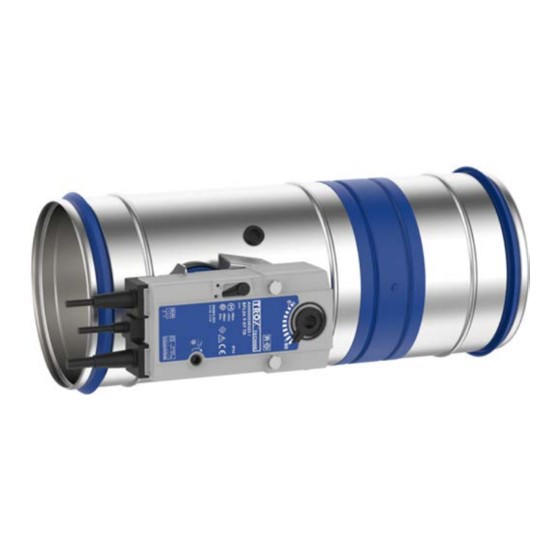
Page 10: Fkrs-Eu With Spring Return Actuator
Maximum switching voltage approx. 30 mΩ Contact resistance 2.3 FKRS-EU with spring return actuator Dimensions and weight Fig. 3: FKRS-EU with spring return actuator Keep clear to provide access for operation Ⓐ Installation side Ⓑ Operating side Weight [kg] Nominal size [mm] ØDN [mm]... - Page 11 Technical data FKRS-EU with spring return actuator Weight [kg] Nominal size [mm] 10.0 10.8 12.0 13.5 15.4 ... with installation kit for flexible ceiling joints (GL) 10.0 10.8 12.0 13.5 15.4 ... with installation kit for installation remote from walls and ceilings (WE) Spring return actuator BFL...
-
Page 12: Transport And Storage
Do not expose the unit to the effects of weather (not even in its packaging). Do not store the unit below -40 °C or above 50 °C. Packaging Properly dispose of packaging material. Fire damper Type FKRS-EU... -
Page 13: Parts And Function
To ensure proper functioning of the fire damper, a test can be carried out. Ä 88 4.1 FKRS-EU with fusible link Fig. 5: FKRS-EU with spring return actuator Casing Temperature sensor Damper blade with seal Inspection access (12 mm) -
Page 14: Fkrs-Eu With Fusible Link And Cover Grille Used As An Air Transfer Unit
FKRS-EU with fusible link and cover gr... 4.3 FKRS-EU with fusible link and cover grille used as an air transfer unit Fig. 6: FKRS-EU with fusible link and cover grille used as an air transfer unit Casing Fusible link Damper blade with seal... -
Page 15: Installation
The class of performance depends on the installation details E = Installation kit For lightweight partition walls ≥ EI 120 W = Fire batt Wall thickness 100 mm – 235 mm Thickness increased near the installation opening Cadolto system Fire damper Type FKRS-EU... - Page 16 The class of performance depends on the installation details E = Installation kit For lightweight partition walls ≥ EI 120 W = Fire batt Wall thickness 100 mm – 235 mm Thickness increased near the installation opening Cadolto system Fire damper Type FKRS-EU...
-
Page 17: Safety Notes On Installation
(0 to 360°)(Fig. 7). The position of the release mechanism is not critical but the mechanism must remain accessible for maintenance. Fire batt systems The following fire batt systems are acceptable (fire batt systems have to be provided by others): Fire damper Type FKRS-EU... -
Page 18: After Installation
Mineral wool slab Paroc Pyrotech Slab 160 Ablative coating Promastopp-CC For installation with a fire batt the FKRS-EU has to be coated. Alternatively, sleeves can be used. Sleeves are to be ordered separately. Fire-resistant cladding When you use installation kit WE, the following mate-... -
Page 19: Solid Walls
If the fire damper is installed as the wall is being erected, the perimeter gap »s« is not required. The open spaces between the fire damper and the wall must be closed off with mortar. Entrapped air is to be avoided. The mortar bed depth should be equal to the thickness of the wall. Fire damper Type FKRS-EU... -
Page 20: Mortar-Based Installation With Flexible Ceiling Joint
If the wall thickness is >115 mm , extend the fire damper on the installation side with an extension piece or a spiral duct. Close off the perimeter gap »s« with mortar. The mortar bed depth must be at least 100 mm. Fill the gap above the mortar bed with mineral wool. Fire damper Type FKRS-EU... -
Page 21: Dry Mortarless Installation With Circular Installation Block Er
Fix the cover plate with four threaded rods (push through installation) or with at least four M6 screws. For solid walls and solid ceiling slabs, suitable steel anchors with building inspectorate approval must be used. Dimensions of installation opening/cover plate [mm] Nominal size ØD1 ☐B Installation opening tolerance + 2 mm Fire damper Type FKRS-EU... -
Page 22: Dry Mortarless Installation With Fire Batt
Ⓐ Installation side Ⓑ Operating side Note: Each fire damper has to be suspended both on the operating side and on the installation side Ä 80. Fire damper Type FKRS-EU... - Page 23 You may use sleeves; if you do not use sleeves, you have to apply ablative coating ②, ≥ 2.5 mm thick, to the fire damper casing Ä ‘Performance class and installation details ’ on page 23. The actuator and release unit must not be coated. Fire damper Type FKRS-EU...
-
Page 24: Dry Mortarless Installation With Wall Face Frame Wa
M8 threaded rods (push through). Installation into a duct with perimeter mortar infill, flush with the wall Provide a reinforcing board ⑦ and attach it to the installation side of the FKRS-EU. Fire damper Type FKRS-EU... - Page 25 The wall surface must be even. Push the fire damper into the duct (with perimeter mortar infill, flush with the wall) and fix it with four M8 threaded rods (push through). Dimensions of installation opening/wall face frame [mm] Nominal size ∅D1 ☐B2 Installation opening tolerance - 20 mm / + 2 mm Fire damper Type FKRS-EU...
-
Page 26: Installation Remote From Solid Walls, Use Of An Installation Kit, Wall Attachment
5.4.6 Installation remote from solid walls, use of an installation kit, wall attachment Fig. 13: Installation remote from solid walls, wall attachment FKRS-EU Fire-resistant cladding Installation kit WE (factory assembled) Support (Promat) Solid wall Duct (sheet steel) Mortar Note: Fire damper and ducting must be suspended Ä 83. Fire damper Type FKRS-EU... -
Page 27: Installation Kit We (Factory Assembled)
Installation kit WE (factory assembled) three sides Solid wall Support Sheet steel duct with fire-resistant cladding Solid ceiling slab or solid wall = ∅DN + 100 ☐A2 Note: Fire damper and ducting must be suspended Ä 83. Fire damper Type FKRS-EU... -
Page 28: Solid Wall
Ä 18 (Fittings with cladding according to instructions from Promat) ≥ 200 mm distance between two fire dampers. Enough clear space is required for installation. Duct connection with flexible connector (recommended) Note: Other installation details upon request. Fire damper Type FKRS-EU... -
Page 29: Installation Remote From Solid Walls, Use Of An Installation Kit, Wall Penetration
Wall penetration according to instructions from Promat ≥ 200 mm distance between two fire dampers. Enough clear space is required for installation. Duct connection with flexible connector (recommended) Note: Other installation details upon request. Fire damper Type FKRS-EU... -
Page 30: Solid Ceiling Slabs
Solid ceiling slabs > Mortar-based installation 5.5 Solid ceiling slabs 5.5.1 Mortar-based installation Fig. 18: Mortar-based installation into solid ceiling slab, suspended or upright FKRS-EU Concrete with perimeter reinforcement Ⓐ Solid ceiling slab Installation side Ⓑ Mortar Operating side Fire damper Type FKRS-EU... - Page 31 Push the fire damper into the installation opening and secure it. Make sure that the distance from the con- necting spigot on the operating side to the ceiling slab is 220 mm. If necessary, extend the fire damper with an extension piece or a spiral duct on the installation side. Fire damper Type FKRS-EU...
- Page 32 If the fire damper is installed as the ceiling slab is being completed, the perimeter gap »s« is not required. Note: – Protect the inside of the damper and the control elements/actuator, e.g. with plastic foil. Fire damper Type FKRS-EU...
-
Page 33: Mortar-Based Installation Into Wooden Beam Ceilings
Structural and fire resistance properties of the ceiling construction, including the attachment to the concrete, have to be evaluated and ensured by others. Fire damper Type FKRS-EU... -
Page 34: Mortar-Based Installation Into Lightweight Ceilings
Structural and fire resistance properties of the ceiling construction, including the attachment to the concrete, have to be evaluated and ensured by others. Fire damper Type FKRS-EU... -
Page 35: Mortar-Based Installation Into Concrete Base
No reinforcement is required for bases with a height of ≤ 100 mm. If the distance to adjacent solid walls is < 150 mm and if the concrete base has been correctly attached, no reinforcement is required on the wall side. Fire damper Type FKRS-EU... - Page 36 Solid ceiling slabs > Mortar-based installation into concr... Fig. 23: Reinforcement plan for concrete bases with a height of 100 to 750 mm or equivalent, e.g. steel anchor or theaded rods Note: Alternative reinforcement plan available upon request. Fire damper Type FKRS-EU...
-
Page 37: Dry Mortarless Installation With Circular Installation Block Er
Fix the cover plate with four threaded rods (push through installation) or with at least four M6 screws. For solid walls and solid ceiling slabs, suitable steel anchors with building inspectorate approval must be used. Dimensions of installation opening/cover plate [mm] Nominal size ∅D1 ☐B Installation opening tolerance + 2 mm Fire damper Type FKRS-EU... -
Page 38: Dry Mortarless Installation With Fire Batt
Fire batt, flush with the floor (only for upright instal- Coating or sleeves lation) Coated mineral wool slabs, ≥ 140 kg/m³ Fire batt, flush with the ceiling (only for suspended Ⓐ Installation side installation) Fire damper Type FKRS-EU... - Page 39 You may use sleeves; if you do not use sleeves, you have to apply ablative coating ②, ≥ 2.5 mm thick, to the fire damper casing Ä ‘Performance class and installation details ’ on page 39. The actuator and release unit must not be coated. Fire damper Type FKRS-EU...
-
Page 40: Installation Remote From Solid Walls With Installation Kit We
Promat) ≥ 200 mm distance between two fire dampers. Enough clear space is required for installation. Duct connection with flexible connector (recommended) Note: Other installation details upon request. Fire damper Type FKRS-EU... -
Page 41: Lightweight Partition Walls With Metal Support Structure
Fig. 27: Lightweight partition wall with metal support structure and cladding on both sides Lightweight partition wall Dry wall screw Lightweight partition wall, installation near the floor Fold the tab inward or cut it off Lightweight partition wall, installation near the Trim panels, according to installation details ceiling Fire damper Type FKRS-EU... - Page 42 1, 2 ☐B1 ☐A = ∅ DN + 80...1200 mm Dry mortarless installation with fire batt ☐A1 = ☐ A + (2 trim panels) Optional trim panels Installation opening tolerance + 2 mm Trim panels are required Fire damper Type FKRS-EU...
-
Page 43: Mortar-Based Installation
Perimeter reinforcing board, 12.5 mm, required for EI 120 S and ∅DN ≥ 224 mm Dry wall screw Ⓐ Mortar Installation side Ⓑ Optional trim panels Operating side For details on the installation into walls of different thickness see Fig. 29 Fire damper Type FKRS-EU... - Page 44 Ä on page 41. Duct connection with flexible connector (recommended) 'Flange-to-flange' installation of two FKRS-EU fire dampers into one installation opening is only possible if both dampers are of the same size (details for other installations are available upon request) Erect a lightweight partition wall according to the manufacturer's instructions: EI 120 S with mineral wool;...
- Page 45 F90 wall, double stud system, W ≥ 150 mm required for F30 wall (W = 200 mm shown) optional Perimeter metal section Dry wall screw Mineral wool (depending on wall construction) Installation details for other wall types are available on request Fire damper Type FKRS-EU...
-
Page 46: Dry Mortarless Installation With Square Installation Kit Tq
If the wall thickness is ≥ 125 mm, fill the rear gap with mineral wool or gypsum mortar and seal it with rein- forcing strips made of the same material as the wall Fig. 31. Fire damper Type FKRS-EU... - Page 47 Reinforcing board, made of wall panels, up to the shown) fire damper casing Perimeter reinforcing strips, 12.5 × 50 mm, only Perimeter metal sections Dry wall screw required for F30 wall Mineral wool (depending on wall construction) optional Trim panels Fire damper Type FKRS-EU...
-
Page 48: Dry Mortarless Installation With Fire Batt
Perimeter metal section Sleeve (either one sleeve on the operating side Dry wall screw (for cladding) only, or one sleeve each on the operating side and on the installation side) Ⓐ Installation side Ⓑ Operating side Fire damper Type FKRS-EU... - Page 49 Ä on page 41. Duct connection with flexible connector (recommended) 'Flange-to-flange' installation of two FKRS-EU fire dampers into one installation opening is only possible if both dampers are of the same size (details for other installations are available upon request) Erect a lightweight partition wall according to the manufacturer's instructions: EI 120 S with mineral wool;...
- Page 50 Fig. 33: Lightweight partition walls, dry mortarless installation with fire batt, EI 60 S Fire batt with ablative coating Reinforcing board Perimeter metal section Dry wall screw Trim panels (screw-fixed to the metal support struc- ture) Installation details for other wall types are available on request Fire damper Type FKRS-EU...
-
Page 51: Installation Remote From Lightweight Partition Walls With Installation Kit We
Fig. 34: Installation remote from lightweight partition walls, wall penetration FKRS-EU Fire-resistant cladding Installation kit WE (factory assembled) Support (Promat) Lightweight partition wall Duct (sheet steel) Mineral wool Note: Fire damper and ducting must be suspended Ä 83. Fire damper Type FKRS-EU... - Page 52 Reinforcing board ≥ 100 mm to be fixed to two Sheet steel duct with fire-resistant cladding studs; from 200 mm to be fixed to one stud. Note: Fire damper and ducting must be suspended Ä 83. Fire damper Type FKRS-EU...
-
Page 53: Reinforcing Board, Fire-Resistant Cladding On Three Sides Support
Sheet steel duct with fire-resistant cladding Reinforcing board ≥ 100 mm to be fixed to two studs; from 200 mm to be fixed to one stud. Note: Fire damper and ducting must be suspended Ä 83. Fire damper Type FKRS-EU... - Page 54 Sheet steel ducts without any openings, with fire-resistant cladding. Acceptable building materials Ä 18 (Fittings with cladding according to instructions from Promat) ≥ 200 mm distance between two fire dampers. Enough clear space is required for installation. Note: Other installation details upon request. Fire damper Type FKRS-EU...
-
Page 55: Dry Mortarless Installation With Installation Kit Gl
≥ 50 mm distance to load-bearing structural elements ≥ 200 mm distance between two installation kits Subsidence of the ceiling slab a ≤ 40 mm For installation, follow the supplied installation manual. Fire damper Type FKRS-EU... -
Page 56: Lightweight Partition Walls With Timber Support Structure
Clear installation opening Screw or pin ☐A1 Opening in the timber support structure, Double layer cladding on both sides of the timber support structure □A1 = □A + (4 trim panels)A Mineral wool (depending on wall construction) Fire damper Type FKRS-EU... - Page 57 ☐A = DN + 150 mm max. Mortar-based installation ☐A Dry mortarless installation with installation kit TQ ☐B1 ☐A = ∅ DN + 80...1200 mm Dry mortarless installation with fire batt Installation opening tolerance + 2 mm Fire damper Type FKRS-EU...
-
Page 58: Mortar-Based Installation
Trim panels, wood sheet, at least 600 kg/m frames) Trim panels (fire-resistant) Up to EI 120 S Wall cladding EI 30 S Wall cladding, wood sheet, at least 600 kg/m Ⓐ Installation side Wall cladding (fire-resistant) Ⓑ Operating side Fire damper Type FKRS-EU... - Page 59 (up to EI 90 S). The mortar bed between the two fire dampers must not exceed 150 mm. 'Flange-to-flange' installation of two FKRS-EU fire dampers into one installation opening is only possible if both dampers are of the same size (details for other installations are available upon request) Duct connection with flexible connector (recommended) ...
-
Page 60: Dry Mortarless Installation With Square Installation Kit Tq
Trim panels, wood sheet, at least 600 kg/m frames) Trim panels (fire-resistant) Up to EI 120 S Wall cladding EI 30 S Wall cladding, wood sheet, at least 600 kg/m Ⓐ Installation side Ⓑ Operating side Fire damper Type FKRS-EU... - Page 61 Position the fire damper with the square installation kit in the centre of the installation opening and push it in up to the cover plate. Fix the cover plate with at least four screws (dry wall screws ∅ ≥ 4.2 mm, a ≥ 10 mm) to the timber support structure. Fire damper Type FKRS-EU...
-
Page 62: Dry Mortarless Installation With Fire Batt
Trim panels (fire-resistant) EI 90 S Wall cladding (fire-resistant) Up to EI 120 S Ⓐ Horizontal timber section / stud, at least 60 x 80 mm Installation side Ⓑ Mineral wool (depending on wall construction) Operating side Fire damper Type FKRS-EU... - Page 63 EI 120 S Trim panels (fire-resistant) EI 90 S Wall cladding (fire-resistant) EI 120 S Ⓐ Horizontal timber section / stud, at least 60 x 80 mm Installation side Ⓑ Mineral wool (depending on wall construction) Operating side Fire damper Type FKRS-EU...
- Page 64 Reinforcing board Trim panels, wood sheet, at least 600 kg/m EI 30 S Trim panels (fire-resistant) EI 30 S Wall cladding, wood sheet, at least 600 kg/m Ⓐ Installation side Wall cladding (fire-resistant) Ⓑ Operating side Fire damper Type FKRS-EU...
- Page 65 For more details see Ä Chapter 5.7.3 ‘Dry mortarless installation with fire batt’ on page 62 Note: Each fire damper has to be suspended both on the operating side and on the installation side Ä 80. Personnel: Fire damper Type FKRS-EU...
- Page 66 Ä on page 56. Duct connection with flexible connector (recommended) 'Flange-to-flange' installation of two FKRS-EU fire dampers into one installation opening is only possible if both dampers are of the same size (details for other installations are available upon request).
-
Page 67: Fire Walls
☐A = ∅ DN + 150 mm max. Mortar-based installation ☐A Dry mortarless installation with square installation kit TQ 1, 2 ☐A1 = ☐A + (2 trim panels) ☐B1 Optional trim panels Installation opening tolerance + 2 mm Fire damper Type FKRS-EU... - Page 68 Dry wall screw Ø 3.9 × 35 mm Carriage bolt, L ≤ 50 mm, with nut and washer UA connecting bracket; construction elements Bracket according to manufacturer's instructions Installation opening depending on installation type Ä on page 67 Fire damper Type FKRS-EU...
- Page 69 Dry wall screw Ø 3.9 × 35 mm Carriage bolt, L ≤ 50 mm, with nut and washer UA connecting bracket; construction elements Bracket according to manufacturer's instructions Installation opening depending on installation type Ä on page 67 Fire damper Type FKRS-EU...
-
Page 70: Mortar-Based Installation
If the wall thickness is > 115 mm, extend the fire damper on the installation side with an extension piece or a spiral duct (attachment or provided by others). Close off the perimeter gap »s« with mortar. Fire damper Type FKRS-EU... -
Page 71: Dry Mortarless Installation With Square Installation Kit Tq
If the wall thickness is > 115 mm, extend the fire damper on the installation side with an extension piece or a spiral duct (attachment or provided by others). Fix the cover plate with at least four screws (dry wall screws ∅ ≥ 4.2 mm, a ≥ 10 mm) to the perimeter metal section. Fire damper Type FKRS-EU... -
Page 72: Shaft Walls
Installation Shaft walls > Shaft walls with metal support struc... 5.9 Shaft walls 5.9.1 Shaft walls with metal support structure Fig. 54: Shaft walls with metal support structure and cladding on one side Fire damper Type FKRS-EU... - Page 73 Option Ⓑ: After cladding the wall, create a square wall opening and brace it with a perimeter metal section. – Installation opening ☐A [mm] Installation type Nominal size ☐A = ∅DN + 150 mm max. Mortar-based installation ☐A Dry mortarless installation with square installation kit TQ ☐B Installation opening tolerance + 2 mm Fire damper Type FKRS-EU...
- Page 74 If the wall thickness is >115 mm, extend the fire damper on the installation side with an extension piece or a spiral duct (attachment or provided by others). Close off the perimeter gap »s« with mortar. Fire damper Type FKRS-EU...
- Page 75 Steel support structure Plasterboard panel Double layer cladding, on one side of the metal stud Optional trim panels system Mortar Reinforcing board of the same material as the wall Wall without adequate fire resistance rating Dry wall screw Fire damper Type FKRS-EU...
- Page 76 If the wall thickness is >115 mm , extend the fire damper on the installation side with an extension piece or a spiral duct. Fix the cover plate with at least four screws (dry wall screws ∅ ≥ 4.2 mm, a ≥ 10 mm) to the perimeter metal section. Fire damper Type FKRS-EU...
-
Page 77: Shaft Walls Without Metal Support Structure
Erect the shaft wall according to the manufacturer's instructions and create an installation opening with rein- forcing strips, see Fig. 58 After cladding the wall, create a square wall opening with reinforcing strips and brace it with a perimeter metal section. Fire damper Type FKRS-EU... - Page 78 Shaft walls > Shaft walls without metal support st... Installation opening ☐A [mm] Installation type Nominal size ☐A = ∅DN + 150 mm max. Mortar-based installation ☐A Dry mortarless installation with square installation kit TQ ☐B Installation opening tolerance + 2 mm Fire damper Type FKRS-EU...
- Page 79 If the wall thickness is >115 mm , extend the fire damper on the installation side with an extension piece or a spiral duct. Fix the cover plate with at least four screws (dry wall screws ∅ ≥ 4.2 mm, a ≥ 10 mm) to the perimeter metal section. Fire damper Type FKRS-EU...
-
Page 80: Suspended Installation Of The Fire
② Push through installation Only steel anchors with certified fire protection qualifica- tion and suitable for the wall or ceiling must be used. Instead of anchors, threaded rods can be used and can be secured using nuts and washers. Fire damper Type FKRS-EU... - Page 81 The riv- Clamp, e.g. Hilti MP-MX, Valraven BIS HD 500 or eted connection must be air-tight. equivalent Ⓐ L-section to EN 10056-1 60 × 30 × 5 mm Installation side Ⓑ Operating side Fire damper Type FKRS-EU...
- Page 82 Danger of falling off! Do not step onto the fire batt! The fire batt cannot carry any loads. Adequate means, e.g. a permanent barrier, must be installed to prevent people from stepping onto the fire batt. Fire damper Type FKRS-EU...
-
Page 83: Fire Damper Remote From Walls And Ceilings
Installation Suspended installation of the fire dam... > Fire damper remote from walls and ce... 5.10.4 Fire damper remote from walls and ceilings Fig. 64: FKRS-EU in a cladded duct FKRS-EU Suspension Solid wall or lightweight partition wall Additional ducting can be used... -
Page 84: Connecting The Ductwork
To remove the transport/installation pro- tection, pull it out of the fire damper on the operating side. 6.3 Limiting duct expansion Fig. 66: FKRS-EU with flexible connectors Flexible connector Ⓐ Installation side Ⓑ Operating side The flexible connectors should be installed in such a way that they can compensate both tension and com- pression. -
Page 85: Cover Grille
224 and above. 6.5 Inspection access Type FKRS-EU fire dampers have an inspection access that is closed with a rubber stopper Ä Chapter 4 ‘Parts and function’ on page 13. The interior of the fire damper should remain accessible for cleaning. -
Page 86: Making Electrical Connections
(wall or ceiling slab). They must not be fixed to the fire damper. Ⓐ NC con- not actuated CLOSED or closed tact OPEN posi- tion is not Note: For the wiring of explosion-proof actuators see reached the additional FKRS-EU-Ex operating manualer Fire damper Type FKRS-EU... -
Page 87: Equipotential Bonding
Fire dampers without flange (circular): Suitable clamps or similar parts may be used for equipoten- tial bonding. It is possible to make drilled holes near the spigot. Fire damper Type FKRS-EU... -
Page 88: Functional Test
ð The damper blade closes and the tab ② on the handle locks into the CLOSED position. Fig. 72: Damper blade position indicator ① Damper blade is closed ② Damper blade is open Fire damper Type FKRS-EU... -
Page 89: Fire Damper With Spring Return Actuator
ð Voltage is supplied again, and the damper blade opens. Check if the damper blade is OPEN, check run- Fig. 74: Damper blade position indicator ning time. ① Damper blade is closed ② Damper blade is open Fire damper Type FKRS-EU... - Page 90 Turn the crank handle into the direction of the arrow ② to just short of the travel stop and hold it. Set the interlock ③ to ð The damper blade remains in the OPEN posi- tion. Remove the crank handle. Fire damper Type FKRS-EU...
-
Page 91: Functional Test With Automatic Control Unit
They may also indicate the need for additional measures which help to maintain the system's function, e.g. cleaning of heavy contamination (dust in extract air systems). Fire damper Type FKRS-EU... -
Page 92: Commissioning
CLOSED fire dampers Fire dampers which close while the ventilation and air conditioning system is running must be inspected before they are opened again in order to ensure Ä ‘Inspection’ on page 93. their correct function Fire damper Type FKRS-EU... -
Page 93: Maintenance
Use only oil or actuator can also be tested with an automatic control grease that is free of resins or acids. unit Ä ‘Functional test with automatic control unit’ on page 91. Fire damper Type FKRS-EU... -
Page 94: Replacing The Fusible Link
Remove the used fusible link. Insert the new fusible link. Put the fusible link holder back into the fire damper and fix it with screws ①. Carry out functional test. Fire damper Type FKRS-EU... -
Page 95: Maintenance
Function OK Fire damper closes when triggered manually or when smoke is detected Fire damper opens after reset – Determine and eliminate the cause of the fault – Repair or replace smoke detector Fire damper Type FKRS-EU... - Page 96 (remote controlled). The system owner can then set the intervals for local tests. C = As required, depending on the degree of contamination Item to be checked Required condition – Remedial action if necessary Fire damper Type FKRS-EU...
-
Page 97: Decommissioning, Removal And Disposal
Disconnect the wiring. Remove the ducts. Close the damper blade. Remove the fire damper. Disposal For disposal, the fire damper must be disassembled. ENVIRONMENT! Dispose of electronic components according to the local electronic waste regulations. Fire damper Type FKRS-EU... -
Page 98: Index
Weights..............9, 10 Installation side............9, 10 Installation situations..........15 Lightweight partition walls with metal support structure and cladding on both sides......41 Lightweight partition walls with metal support structure and cladding on one side......72 Fire damper Type FKRS-EU... -
Page 99: Amendment To Fkrs-Eu/001 Up To
Amendment to FKRS-EU/001 Amendment to FKRS-EU/001 The installation and operating manual FKRS-EU 09/2016 for the DoP / FKRS-EU / DE / 003 is being amended: Application: Mortar-based installation with perimeter mortar infill in a solid wood wall / CLT wall ... -
Page 100: Fkrs-Eu/004
between the two fire dampers must not exceed 150 mm. 'Flange-to-flange' installation of two FKRS-EU fire dampers into one installation opening is only possible if both dampers are of the same size (details for other installations are available upon request) Duct connection with flexible connector (recommended) ... - Page 101 If the wall thickness is > 130 mm, extend the fire damper on the installation side with an extension piece or a spiral duct (attachment or provided by others). Fix the cover plate to the wall with min. four screws (dry wall screws ∅ ≥ 4.2 mm, a ≥ 10 mm). Fire damper Type FKRS-EU...
- Page 102 Installation – Solid wood walls > Dry mortarless installation with fire batt 5.x.3 Dry mortarless installation with fire batt Fig. x: Dry mortarless installation in a solid wood wall / CLT wall FKRS-EU, nominal width 100 – 315 7.14 Reinforcing board of the same material as Fire batt with ablative coating the wall (with W <...
- Page 103 ≥ 40 mm distance to load-bearing structural elements 'Flange-to-flange' installation of two FKRS-EU fire dampers into one installation opening is only possible if both dampers are of the same size (details for other installations are available upon request) Duct connection with flexible connector (recommended) ...
- Page 104 Amendment to FKRS-EU/002 Amendment to FKRS-EU/002 The installation and operating manual FKRS-EU 09/2016 for the DOP / FKRS-EU / DE / 003 is being amended: Application: Dry mortarless installation with fire batt into a solid wall Dry mortarless installation into a lightweight partition wall, with a fire batt ...
- Page 105 Note: The following pages will be listed in the last chapter under the section "Amendment to FKRS-EU" until the next publication cycle of the installation and operating manual FKRS-EU. After the publication cycle, these pages will appear in the document in accordance with the chapter numbering.
- Page 106 Note: For use in Europe (outside Germany), the declarations of performance for fire dampers FK-EU and FKRS-EU apply and these have been extended to include use with combined penetration seal. The materials and building products specified in this operating and installation manual for the combined penetration seal are a component of this declaration of performance and do not require any additional supporting documents.
- Page 107 09/2016. Note: The following pages will be listed in the last chapter under the section "Amendment to FKRS-EU/004" until the next publication cycle of the installation and operating manual FKRS-EU. After the publication cycle, these pages will appear in the document in accordance with the chapter numbering.
Need help?
Do you have a question about the FKRS-EU and is the answer not in the manual?
Questions and answers