Advertisement
Quick Links
FK-EU
1.1 –
X FK-EU
X
testregistrierung
FK-EU with fusible link
for 72 °C or 95 °C
CE compliant according
to European regulations
With TROXNETCOM
as an option
ATEX certification
Tested to VDI 6022
06/2015 – DE/en
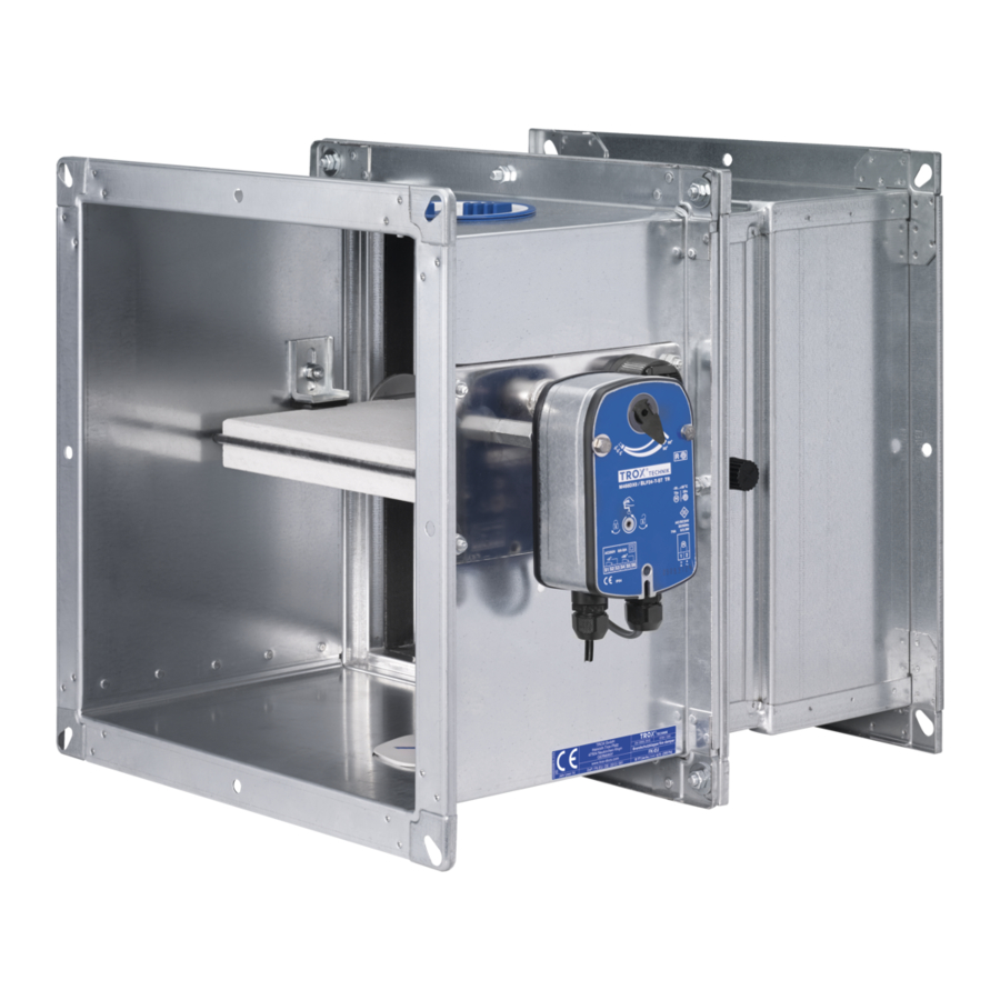
Fire dampers
Type FK-EU
For diverse applications
Rectangular fire damper for the isolation of duct penetrations between
fire compartments, for a variety of installation situations,
available in many different sizes and constructions
■
Nominal sizes 200 × 200 – 1500 × 800 mm, in increments of 1 mm
■
Low differential pressure and sound power level
■
Explosion-proof construction (ATEX) as an option
■
Air transfer damper as an option
■
Optional stainless steel casing or powder-coated casing
for increased corrosion protection
■
Integration into the central BMS with TROXNETCOM
■
Universal installation options
Optional equipment and accessories
■
Electric actuator 24 V/230 V
■
Release temperature 72/95 °C
■
Duct smoke detector RM-O-3-D
1
K 4 – 1.1 – 1
Advertisement

Related Manuals for Trox Technik FK-EU


Summary of Contents for Trox Technik FK-EU
- Page 1 FK-EU 1.1 – X FK-EU testregistrierung Fire dampers Type FK-EU FK-EU with fusible link for 72 °C or 95 °C CE compliant according to European regulations For diverse applications With TROXNETCOM Rectangular fire damper for the isolation of duct penetrations between...
-
Page 2: General Information
Quick sizing 1.1 – 38 Free area, resistance coefficient and correction values 1.1 – 40 1.1 – 42 Dimensions and weight – FK-EU Dimensions and weight – FK-EU/.../Z4* 1.1 – 43 Dimensions and weight – FK-EU/.../ZEX* 1.1 – 44 Dimensions and weight – FK-EU/.../Z**RM 1.1 –... - Page 3 Fire dampers General information FK-EU FK-EU with fusible link FK-EU with spring return actuator Variants Product examples FK-EU with spring return actuator FK-EU as air transfer damper (explosion- proof) 06/2015 – DE/en K 4 – 1.1 – 3...
- Page 4 General information FK-EU Application Accessories Description – TROX fire dampers of Type FK-EU, – Installation subframe and installation kit with CE marking and declaration for dry mortarless installation in solid walls of performance, for the isolation of duct – Installation kit for installation into solid non-...
- Page 5 Fire dampers General information FK-EU Construction features Dry mortarless installation: – Rectangular or square construction, – In solid walls: with installation kit rigid casing, both flanges with fixing holes and installation subframe E1/E2 – Suitable for the connection of ducts, –...
- Page 6 95 °C (use in warm air ventilation systems) by a fusible link. The release mechanism is accessible and can be tested from the outside. Schematic illustration of FK-EU with fusible link ① Casing ⑥ Fusible link ② Damper blade ⑦...
- Page 7 The spring return actuator is fitted with limit switches that can be used for capturing the damper blade position. Schematic illustration of FK-EU with spring return actuator ① Casing ⑤ Inspection access ② Damper blade ⑥...
- Page 8 RedMax-15-BF TR II 3D c T80 °C II 3G c IIC T6 –40 to 40 °C 10 m/s ATEX certification Schematic illustration of FK-EU with spring return actuator, explosion-proof construction (e.g. ExMax-15-BF TR) ① Casing ⑥ Temperature sensor ② Damper blade ⑦...
- Page 9 A second temperature sensor monitors the ambient temperature. If the supply voltage fails, the damper closes. Air transfer dampers consist of an FK-EU fire damper, an RM-O-3-D duct smoke detector with general building inspectorate licence Z-78.6-125, a spring return actuator (24 V AC/DC or 230 V AC) with two integral limit switches, and cover grilles on both ends.
-
Page 10: Correct Use
Fire dampers Correct use FK-EU Design information Incorrect use – Approved only for use in ventilation Never use the fire damper: and air conditioning sytems – without specially approved attachments – A class of performance up to EI 120 in areas with potentially explosive atmospheres , i ↔... - Page 11 Fire dampers Correct use FK-EU Correct use on the face of, adjacent to and remote from solid walls Mortar-based Dry mortarless Minimum installation installation Performance class thick ness Construction Installation loca tion Casing length [mm] and buil ding material EI TT (v –h...
- Page 12 – gross density ≥ 600 kg/m³ N = mortar-based installation, W = fire batt ¹ For FK-EU as air transfer damper only up to B × H = 500 × 500 mm K 4 – 1.1 – 12 06/2015 – DE/en...
- Page 13 Fire dampers Correct use FK-EU Correct use in lightweight partition walls and fire walls Mortar-based Dry mortarless Minimum installation installation Performance class thick ness Construction Installation loca tion Casing length [mm] and buil ding material EI TT (v –h , i ↔ o) S L = 375...
- Page 14 Fire dampers Correct use FK-EU Installation orientation with horizontal ducts Installation orientation ① Release mechanism (mechanical or spring return actuator) Installation orientation when used as an air transfer damper with horizontal ducts ① Duct smoke detector ② Spring return actuator K 4 –...
- Page 15 Accessories 1 Installation kit – installation in solid walls FK-EU Application Materials and surfaces Description – Installation in solid walls without perimeter – Installation subframe made of galvanised steel mortar infill (dry mortarless installation) and with intumescent seal / E1 / requires an installation subframe –...
- Page 16 Accessories 1 Installation kit – installation in solid walls FK-EU FK-EU with installation subframe and installation kit E1 or E2 L = 50 0 B + 1 7 H + 1 Installation subframe and installation kit E1 or E2, consisting of: ①...
- Page 17 Installation kit for installation into solid non-load-bearing walls with flexible ceiling joint L [mm] Order code FK-EU with installation kit GM L = 50 0 Installation kit GM, consisting of: ③ Filler strip ① Cover section with intumescent seal ④...
- Page 18 L = 500 mm Installation kit for dry mortarless installation on the face of solid walls L [mm] Order code FK-EU with installation kit WA L = 50 0 Installation kit WA, consisting of: ② Installation kit ①...
- Page 19 Installation kit for dry mortarless installation adjacent to solid walls, with x ≤ 260 mm L [mm] Order code FK-EU with installation kit WV L = 50 0 Installation kit WV, consisting of: ③ Fire damper or duct section up for refurbishment ①...
- Page 20 Accessories 1 Installation kit – for installation remote from solid walls FK-EU Application Materials and surfaces Description – Dry mortarless installation remote from solid – Installation kit made from special insulation walls or ceiling slabs requires an installation kit material and mineral wool strips / WE / –...
- Page 21 Accessories 1 Installation kit – for installation remote from solid walls FK-EU FK-EU with installation kit WE L = 50 0 Installation kit WE, consisting of: ③ Calcium silicate boards (provided by others) ① Installation kit (provided by others) ④ Duct, galvanised steel (provided by others) ②...
- Page 22 Installation kit for dry mortarless installation in lightweight partition walls, fire walls and shaft walls L [mm] Order code FK-EU with installation kit ES ~ 9 0 B + 9 5 / 1 9 0 H + 9 5...
- Page 23 Order code GL100¹ ¹For wall thickness 100 mm when 50 mm sections are used. Other wall thicknesses and section widths upon request. FK-EU with installation kit GL100 B + 8 3 L = 50 0 26 0 Installation kit GL100, consisting of: ③...
-
Page 24: Cover Grille
Germany only for Type FK fire dampers used as air transfer dampers, Cover grille general building inspectorate licence Z-6.50-2031. Cover grilles for FK-EU · FK-EU-1 · FK-EU-2 · FK-EU-7 / A0 / / 0A / Operating side Installation side... - Page 25 Accessories 2 Cover grille FK-EU Cover grille The distance »a« between the open damper blade and the spigot should be 50 mm. 120 / 260 ① Operating side ③ Cover grille, mesh aperture 10 mm × 10 mm, wire width 2 mm ②...
- Page 26 – The fixing holes in the spigot plates and extension pieces match those in the fire damper flanges – Spigot plates are also available separately. Circular spigot plate for FK-EU · FK-EU-1 · FK-EU-2 · FK-EU-7 / R0 / / 0R / Operating side...
- Page 27 Accessories 2 Circular spigot FK-EU Circular spigot The distance »a« between the open damper blade and the spigot should be 50 mm. ① Operating side ③ Circular spigot ② Installation side ④ Extension piece Extension pieces and spigot plates are supplied factory assembled...
-
Page 28: Flexible Connector
– The fixing holes in the flexible connectors and extension pieces match those in the fire damper flanges – Flexible connectors are also available separately Flexible connector for FK-EU · FK-EU-1 · FK-EU-2 · FK-EU-7 / S0 / / 0S / Operating side Installation side... - Page 29 Accessories 2 Flexible connector FK-EU Flexible connector The distance »a« between the open damper blade and the flexible connector should be 50 mm. ① Operating side ③ Flexible connector ② Installation side ④ Extension piece Extension pieces are supplied factory assembled.
- Page 30 Accessories 2 Extension piece FK-EU Application Materials and surfaces Description – Fire dampers ordered with flexible connector, – Extension pieces made of galvanised sheet cover grille or circular spigot plate steel (and powder-coated silver grey, are supplied including extension piece.
- Page 31 Accessories 2 Extension piece FK-EU Extension piece The distance »a« between the open damper blade and the flexible connector should be 50 mm. L = 375 bzw. 500 L = 375 bzw. 500 L = 500 ① Operating side ③ Flexible connector, on operating and/or installation side ②...
-
Page 32: Limit Switch
Limit switch (explosion-proof) for damper blade position OPEN Z02EX Order code detail Limit switches (explosion-proof) for damper blade positions CLOSED and OPEN Z03EX ATEX areas of application for the FK-EU Release mechanism Marking Ambient temperature Maximum airflow velocity Fusible link II 2D c T80 °C/II 2G c IIC T6... - Page 33 Joventa SFR1.90 T SLC (24 V) Order code detail Spring return actuator BLF for FK-EU in sizes up to B × H ≤ 800 × 400 mm. Spring return actuator BF for FK-EU in sizes from B × H ≤ 800 × 400 mm.
- Page 34 B(L)F24-T ST TR (cover grilles both sides required [AA]) Spring return actuator BLF for FK-EU in sizes up to B × H ≤ 800 × 400 mm. Spring return actuator BF for FK-EU in sizes from B × H ≤ 800 × 400 mm.
- Page 35 AS-RM/BD-UE, B(L)F24-T-ST TR and RM-O-3-D ZA11 Spring return actuator BLF for FK-EU in sizes up to B × H ≤ 800 × 400 mm. / ZA07 Spring return actuator BF for FK-EU in sizes from B × H ≤ 800 × 400 mm.
- Page 36 Attachments Duct smoke detectors FK-EU General Application Description – To prevent smoke from spreading in buildings, RM-O-3-D: it is extremely important that the smoke – Duct smoke detector for fire dampers is detected at an early stage. and smoke protection dampers –...
- Page 37 Fire dampers Free area, resistance coefficient and correction values FK-EU B [mm] H [mm] Parameter A [m²] 0.02 0.027 0.034 0.041 0.048 0.055 0.062 0.069 0.076 0.083 Ζ 1.12 0.94 0.77 0.71 0.65 0.59 0.53 0.53 0.47 0.47 A [m²] 0.029...
- Page 38 Fire dampers Free area, resistance coefficient and correction values FK-EU B [mm] H [mm] Parameter A [m²] 0.108 0.131 0.153 0.176 0.198 0.221 0.243 0.266 0.288 Ζ 0.78 0.69 0.64 0.59 0.54 0.49 0.49 0.49 0.44 A [m²] 0.12 0.145 0.17...
- Page 39 Fire dampers Dimensions and weight – FK-EU FK-EU FK-EU with fusible link Dimensions FK-EU with fusible link L = 375 oder 500 ~ 175 W: 115 mm (B < 250 mm: 94 mm) ① Keep clear to provide access to the release mechanism...
- Page 40 Fire dampers Dimensions and weight – FK-EU/.../Z4* FK-EU FK-EU with spring return actuator (FK-EU/.../Z4*) Dimensions FK-EU with spring return actuator L = 375 oder 500 ~ 100 ~ 175 W: 115 mm (B < 250 mm: 94 mm) ① Keep clear to provide access to the spring return actuator...
- Page 41 Fire dampers Dimensions and weight – FK-EU/.../ZEX* FK-EU FK-EU with explosion-proof actuator (FK-EU/.../ZEX1* and ZEX3*) Dimensions FK-EU with spring return actuator (explosion-proof) L = 375 oder 500 ~ 200 ~ 220 W: 115 mm (B < 250 mm: 94 mm) ①...
- Page 42 Fire dampers Dimensions and weight – FK-EU/.../Z**RM FK-EU FK-EU as air transfer damper (FK-EU/.../Z**RM) Dimensions FK-EU as air transfer damper L = 375 oder 500 ~ 100 ~ 175 W: 115 mm (B < 250 mm: 94 mm) ① Keep clear to provide access to the duct smoke detector...
- Page 43 Fire dampers Dimensions – Duct connection FK-EU Flange – uneven number of holes Dimensions 300 300 17,5 Flange – even number of holes 300 300 17,5 Dimensions [mm] 1100 1300 1500 B or H 1000 1200 1400 No. of holes horizontally (B)* No.
-
Page 44: Specification Text
Fire dampers Specification text FK-EU Rectangular or square fire dampers Special characteristics Description for the isolation of duct penetrations – Declaration of performance according between fire compartments.Tested for fire to Construction Products Regulation This specification text resistance properties to EN 1366-2, with CE –... - Page 45 Fire dampers Specification text FK-EU Type Accessories 1 Order options FK-EU Fire damper No entry: none E1 – GL 100³ Construction No entry: standard construction Accessories 2 Casing powder-coated RAL 7001 No entry: none 2¹ Casing made of stainless steel A0 –...
Need help?
Do you have a question about the FK-EU and is the answer not in the manual?
Questions and answers