Trox Technik FKR-EU Installation And Operating Manual
Hide thumbs
Also See for FKR-EU:
- Manual (36 pages) ,
- Supplementary operating manual (17 pages) ,
- Installation and operating manual (64 pages)

Related Manuals for Trox Technik FKR-EU


Summary of Contents for Trox Technik FKR-EU
- Page 1 Installation and operating manual GB/en Fire damper FKR-EU according to Declaration of Performance DoP / FKR-EU / DE / 004 Read the instructions prior to performing any task!
- Page 2 TROX GmbH Heinrich-Trox-Platz 47504 Neukirchen-Vluyn, Germany Germany Phone: +49 (0) 2845 2020 Fax: +49 (0) 2845 202-265 E-mail: trox-de@troxgroup.de Internet: http://www.troxtechnik.com Translation of the original A00000092704, 1, GB/en 02/2022 © 2021 Fire damper FKR-EU...
- Page 3 To ensure that your request is processed as quickly as possible, please keep the following information ready: Product name TROX order number Delivery date Brief description of the fault Online www.troxtechnik.com Phone +49 2845 202-400 Fire damper FKR-EU...
- Page 4 Warning – danger zone. NOTICE! Potentially hazardous situation which, if not avoided, may result in property damage. ENVIRONMENT! Environmental pollution hazard. Tips and recommendations Useful tips and recommendations as well as informa- tion for efficient and fault-free operation. Fire damper FKR-EU...
-
Page 5: Table Of Contents
5.8.1 General ..........92 2.3 FKR-EU with spring return actuator ..5.8.2 Mortar-based installation ...... 93 2.4 FKR-EU with fusible link and cover grille 5.8.3 Dry mortarless installation with installa- on both sides as an upstream shutter for tion kit TQ ..........95 the air transfer unit ........ - Page 6 Commissioning ..........147 Maintenance ..........148 10.1 General ..........148 10.2 Replacing the fusible link ..... 149 10.3 Inspection, maintenance and repair measures ..........151 Decommissioning, removal and disposal . 153 Nomenclature ..........154 Change history ..........Index.............. 160 Fire damper FKR-EU...
-
Page 7: Safety
Operation of the fire dampers is allowed only in compliance with installation regulations and the technical data in this installation and operating manual. Modifying the fire damper or using replacement parts that have not been approved by TROX is not permitted. Fire damper FKR-EU... -
Page 8: Qualified Staff
Specialist personnel are individuals who have sufficient professional or technical training, knowledge and actual experience to enable them to carry out their assigned duties, understand any potential hazards related to the work under consideration, and recognise and avoid any risks involved. Fire damper FKR-EU... -
Page 9: Technical Data
Condensation and the intake of humid fresh air have to be avoided as otherwise operation will be impaired or not possible. For FKR-EU in Ex construction, see the supplementary operating manual. Leakage rate of the fire damper system tested at 300 Pa negative pressure. - Page 10 Ä Chapter 5.1 ‘Installation situations’ Notified body The last two digits of the year in which the CE on page 24 marking was affixed Type Year of manufacture Order number Fire damper FKR-EU...
-
Page 11: Fkr-Eu With Fusible Link
Installation side Flange construction Operating side Keep clear to provide access for operation Ä 12 . Weight of FKR-EU with fusible link, see table Limit switch Connecting cable length / cross section 1 m / 3 × 0.34 mm²... - Page 12 ÆD ÆD α 45 ° 30 ° 22.5 ° No. of holes Weight of FKR-EU 14.1 16.4 21.3 25.7 28.6 Weight of FKR-EU with spigot 19.5 21.8 33.1 37.8 42.6 49.7 58.7 67.3 and installation kit TQ Fire damper FKR-EU...
-
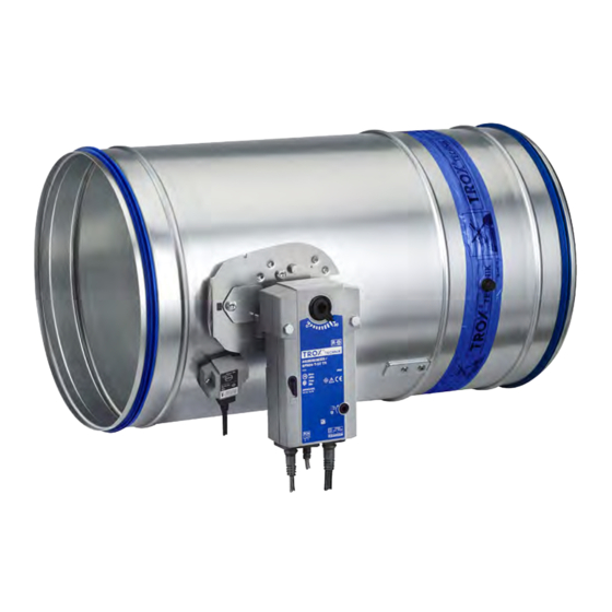
Page 13: Fkr-Eu With Spring Return Actuator
Fig. 3: FKR-EU with Belimo spring return actuator Spigot construction Installation side Flange construction Operating side Keep clear to provide access for operation Ä 12 . Weight of FKR-EU with fusible link + approx. 1 kg (BFN...) or 3 kg (BF...), see table Fire damper FKR-EU... - Page 14 Technical data FKR-EU with spring return actuator Spring return actuator BFN... Construction 230-T TR 24-T-ST TR Supply voltage 230 V AC, 50/60 Hz 24 V AC/DC, 50/60 Hz Functional range 198 – 264 V AC 19.2 – 28.8 V AC 21.6 –...
- Page 15 Technical data FKR-EU with spring return actuator Spring return actuator BF... Construction BF230-TN-2 TR BF24-TN-ST-2 TR Supply voltage 230 V AC, 50/60 Hz 24 V AC/DC, 50/60 Hz Functional range 198 – 264 V AC 19.2 – 28.8 V AC 21.6 –...
- Page 16 Fig. 4: FKR-EU with Siemens spring return actuator Spigot construction Installation side Flange construction Operating side Keep clear to provide access for operation Ä 12 . Weight of FKR-EU with fusible link + approx. 1.4 kg (GNA...) or 2.5 kg (GGA...), see table Fire damper FKR-EU...
- Page 17 Technical data FKR-EU with spring return actuator Spring return actuator GNA... Construction 326.1E 126.1E Supply voltage 230 V AC, 50/60 Hz 24 V AC, 50/60 Hz / 24 – 48 V DC Functional range 198 – 264 V AC 19.2 – 28.8 V AC 19.2 –...
- Page 18 Technical data FKR-EU with spring return actuator FKR-EU with Schischek explosion-proof spring return actuator The FKR-EU can also be supplied with Schischek explosion-proof spring return actuator on request: ExMax-15-BF-TR RedMax-15-BF-TR For further information, see "Supplementary operating manual for explosion-proof fire dampers Type FKR-EU".
-
Page 19: Fkr-Eu With Fusible Link And Cover Grille On Both Sides As An Upstream Shutter For The Air Transfer Unit
Technical data FKR-EU with fusible link and cover grille on bot... 2.4 FKR-EU with fusible link and cover grille on both sides as an upstream shutter for the air transfer unit Dimensions and weight Fig. 5: FKR-EU with fusible link... -
Page 20: Supply Package, Transport And Storage
Store the product in a dry place and away from direct sunlight. Do not expose the unit to the effects of weather (not even in its packaging). Do not store the product below -40 °C or above 50 °C. Fire damper FKR-EU... -
Page 21: Parts And Function
( 95 °C in warm air ventilation systems). If the damper blade closes due to a temperature increase (i.e. in the event of a fire), it must not be reopened. 4.2 FKR-EU with fusible link Fig. 7: FKR-EU with spring return actuator (Fig. Spigot construction) Casing Damper blade with seal... -
Page 22: Fkr-Eu With Spring Return Actuator And Duct Smoke Detector
T-piece. The duct smoke detector must always be placed at the top. Deviating arrangements are possible, provided that Fig. 8: FKR-EU with spring return actuator and duct the specifications of the general building inspectorate smoke detector in a rectangular duct licence of the duct smoke detector are observed. -
Page 23: Fk-Eu With Fusible Link And Cover Grille On
4.5 FK-EU with fusible link and cover grille on both sides as an upstream shutter for the air transfer unit Fig. 10: FKR-EU with fusible link and cover grille as an upstream shutter for the air transfer unit (Fig. Spigot construction) -
Page 24: Installation
N = Mortar-based installation E = Installation kit The class of performance depends on the installation details W = Fire batt Thickness increased near the installation opening E = Dry mortarless installation Cadolto system Depending on local conditions Fire damper FKR-EU... - Page 25 Gypsum wall boards EN12859 E = Installation kit The class of performance depends on the installation details W = Fire batt Thickness increased near the installation opening E = Dry mortarless installation Cadolto system Depending on local conditions Fire damper FKR-EU...
-
Page 26: Safety Notes Regarding Installation
– Do not remove the transport and installation pro- – Be careful when carrying out any work. tection (if any) until installation is complete. – Wear protective gloves, safety shoes and a hard hat. Fire damper FKR-EU... - Page 27 When installing the FKR-EU, the structural proper- After installation ties of the supporting construction (wall / ceiling) must be ensured by others, even in the event of a Clean the fire damper.
- Page 28 (attachment or extension by Keep clear to provide access for operation Ä Chapter 6 ‘Accesso- others) on the installation side ries’ on page 137 . Fire damper FKR-EU...
- Page 29 With shortened cover plate Separate installation opening 80 – 225 mm and/or 80 – 600 mm with flange construction The perimeter gap is ≤ 225 mm with mortar-based installation and 40 – 600 mm with fire batt. Fire damper FKR-EU...
- Page 30 In / in combination with solid wood ceiling E / A, B, D – F E / – In / in combination with wooden beam ceiling E / A, B, D – F E / – Historical wooden beam ceilings Fire damper FKR-EU...
- Page 31 Unless otherwise stated in the installation details, min- eral wool with a gross density of ≥ 80 kg/m³ and a melting point of ≥ 1000 °C must be used. Fire damper FKR-EU...
- Page 32 Installation with installation kit For installation without a mortar-mix, the installation kit TQ can be used (only FKR-EU in spigot construc- tion). The installation kit is assembled on the fire damper at the factory. Fixing to the wall / ceiling slab is car- ried out according to the respective installation details.
- Page 33 [mm] FKR-EU Requirements for wall and ceiling systems FKR-EU fire dampers must be installed in wall and ceiling systems if these walls and ceiling slabs have been erected in compliance with the relevant regula- tions and according to the manufacturers' instructions, and if the information on the respective installation sit- uation applies and the following requirements are met.
- Page 34 (load-bearing wall constructions on request). The structural properties of the wall must be Fig. 18: Distance from the FKR-EU to other TROX fire ensured by others and any necessary compensation dampers in mortar-based installation measures, especially with large installation open-...
- Page 35 Shaft wall between two solid walls, without corner formation Wall thickness W ≥ 50 mm. If reinforcing boards are required, they must be screwed on at intervals of approx. 100 mm. Fire damper FKR-EU...
- Page 36 Ceiling thickness D ≥ 140 mm or D ≥ 112.5 mm with supplementary fire-resistant cladding. Wooden beam ceilings Wooden beam or gluelam construction. Ceiling thickness D ≥ 142.5 mm (ceiling-dependent) with supplementary fire-resistant cladding. Historical wooden beam ceilings F30. Fire damper FKR-EU...
-
Page 37: Installation Kits
The installation kit TQ is an integral component of the fire damper and must be ordered together with the damper. Fig. 19: Supply package and installation of installation kit TQ for dry mortarless installation FKR-EU in spigot construction 2.11 Installation kit TQ with cover plate and intumescent seal... -
Page 38: Solid Walls
Observe maximum permitted size of the fire batt! Flange construction 80 – 225 mm or 80 – 600 mm Additional requirements: solid walls Solid wall Ä on page 34 Ä Distances and installation orientations, ‘Dis- tances’ on page 29 Fire damper FKR-EU... -
Page 39: Mortar-Based Installation
FKR-EU Flange construction 342 mm Mortar Spigot construction 40 – 225 mm Solid wall Flange construction 80 – 225 mm Spigot construction 370 mm Up to EI 120 Fire damper FKR-EU... - Page 40 FKR-EU Spigot construction 370 mm Mortar Flange construction 342 mm 3.14 Solid wall made of gypsum ball boards EN 12859 Installation near the floor analogous to (formerly DIN 18163) Up to EI 90 S Solid ceiling slab Fire damper FKR-EU...
- Page 41 For installation details FK2-EU, see the installation and operating manual for this fire damper type. Distance to load-bearing structural elements ≥ 40 mm Distance of FKR-EU to a FK-EU 75 – 225 mm (flange construction 80 – 225 mm) Fire damper FKR-EU...
- Page 42 Note on flexible ceiling joint: representative illustration. The distance to the ceiling depends on the design of the flexible ceiling joint, the expected ceiling subsidence and the specifications of the wall manufacturer. Additional requirements: mortar-based installation into solid walls Ä Solid wall on page 34 Fire damper FKR-EU...
-
Page 43: Mortar-Based Installation - Multiple Occupancy Of An Installation Opening
Fig. 26: Mortar-based installation – multiple occupancy of an installation opening FKR-EU Solid ceiling slab (load-bearing component) Mortar Spigot construction 40 – 225 mm Concrete Flange construction 80 – 225 mm Solid wall (load-bearing component) Up to EI 90 S Fire damper FKR-EU... - Page 44 (Æ nominal width) and the overall area of the fire dampers (4.8 m The dampers can be arranged in one or two rows. Distance to load-bearing structural elements ≥ 40 mm Fire damper FKR-EU...
-
Page 45: Dry Mortarless Installation With Fire Batt
Flange construction 342 mm Coated board system Spigot construction 40 – 600 mm Solid wall Flange construction 80 – 600 mm Solid ceiling slab Installation near the floor analogous to Spigot construction 370 mm Up to EI 60 S Fire damper FKR-EU... - Page 46 Solid wall Ä on page 34 Fire batt systems, installation details, distances / dimensions Ä on page 32 Ä Chapter 5.14 ‘Fixing the Suspension and fixing fire damper’ on page 135 Fire damper FKR-EU...
-
Page 47: Lightweight Partition Walls
Lightweight partition walls > General 5.6 Lightweight partition walls 5.6.1 General Lightweight partition wall with metal support structure and cladding on both sides Ä Fig. 33 Fig. 30: Lightweight partition wall with metal support structure and cladding on both sides, caption Fire damper FKR-EU... - Page 48 Lightweight partition wall "flange to flange" Fig. 31: Lightweight partition wall with metal support structure and cladding on both sides, flange to flange, Æ nominal width 315 – 400, caption Ä Fig. 33 For details see Fig. 30 Fire damper FKR-EU...
- Page 49 Lightweight partition walls > General Fig. 32: Lightweight partition wall with metal support structure and cladding on both sides, flange to flange, Æ nominal width 450 – 800, caption Ä Fig. 33 For details see Fig. 30 Fire damper FKR-EU...
- Page 50 Installation Lightweight partition walls > General Compartment wall Fig. 33: Compartment wall with metal support structure and cladding on both sides Fire damper FKR-EU...
- Page 51 Solid ceiling slab / solid floor Closed side of metal section must face the Dry wall screw installation opening Screw or steel rivet Mineral wool (depending on wall construction) UW section 7.1a UW section, cut in and bent or cut off Fire damper FKR-EU...
- Page 52 Fig. 34: Metal support structure of compartment wall, single and double stud system Dry wall screw UW section Hexagon head screw M6 CW section Carriage bolt, L ≤ 50 mm, with washer and nut UA section Steel rivet Installation opening according to installation 5.14 Angle bracket details Fire damper FKR-EU...
- Page 53 ☐A1 = ☐A + (2 × trim panels / 4 × trim panels) Optional trim panels (max. 25 mm) Installation opening tolerance ± 2 mm Installation kit TQ is available only for FKR-EU with spigot Trim panels according to installation details required Additional requirements: lightweight partition walls...
-
Page 54: Mortar-Based Installation
Flange construction 342 mm Solid ceiling slab Installation near the floor analogous to Mineral wool (depending on wall construction) optional 6.11 Insulating strip (depending on wall construction) – Up to EI 90 S Steel support structure (box section) Fire damper FKR-EU... - Page 55 Mineral wool (depending on wall construction) Up to EI 60 S 6.11 Insulating strip (depending on wall construction) – EI 30 S 7.10 Trim panels (screw-fixed to metal support struc- ture) 7.13 Cladding Fire damper FKR-EU...
- Page 56 Up to EI 90 S port structure, cladding on both sides Up to EI 60 S Mineral wool (depending on wall construction) EI 30 S 7.10 Trim panels 7.13 Cladding 7.14 Reinforcing board of the same material as the wall Fire damper FKR-EU...
- Page 57 The number of fire dampers in an installation opening is limited by their size (B × H for FK2-EU and /or Æ nominal width for FKR-EU) and the overall area of the fire dampers (1.2 m²). Alternative installation orientations of side-by-side, under or on top of one another possible. Details are available ...
- Page 58 Ä Chapter 5.6.1 ‘General’ on page 47 Frame construction, size-dependent, Distance of FKR-EU to a FK-EU 75 – 225 mm (flange construction 80 – 225 mm) Mortar-based installation into a lightweight partition wall, below a flexible ceiling joint Fig.
-
Page 59: Mortar-Based Installation - Multiple Occupancy Of An Installation Opening
5.6.3 Mortar-based installation – multiple occupancy of an installation opening Fig. 40: Mortar-based installation – multiple occupancy of an installation opening FKR-EU Solid wall (load-bearing component) Mortar Solid ceiling slab (load-bearing component) Concrete Up to EI 90 S Fire damper FKR-EU... - Page 60 Flange construction 80 – 225 mm Compartment wall or safety wall with metal sup- Depending on the wall structure port structure, cladding on both sides Up to EI 90 S Mineral wool (depending on wall construction) 7.10 Trim panels Fire damper FKR-EU...
- Page 61 ≥ 40 mm If the actuators are located between the fire dampers, sufficient free space for inspection must be provided. The mortar bed width is not allowed to exceed 225 mm, provide separate trimmers if necessary. Fire damper FKR-EU...
-
Page 62: Dry Mortarless Installation With Installation Kit Tq
Up to EI 90 S 6.13 Mineral wool strips A1, ≤ 5 mm thick, ≤ 1000°C, filler as an alternative Note: – valid for all wall constructions and wall thicknesses. valid for all wall thicknesses with a single stud frame. Fire damper FKR-EU... - Page 63 Installation kit TQ (factory assembled) 7.14 Reinforcing board made of wall panels (rein- Lightweight partition wall with metal support forcing board or alternatively wall cladding on structure, cladding on both sides the back, up to the fire damper casing) Fire damper FKR-EU...
- Page 64 Lightweight partition wall or compartment wall, to 400 mm) or 12 (for nominal widths from 450 mm) Ä on page 34 dry wall screws Æ ≥ 4.2 mm to the metal support Installation kit TQ, Ä on page 32 structure Fire damper FKR-EU...
-
Page 65: Dry Mortarless Installation Without Installation Kit
Create a circular installation opening with nominal width +20 mm. Chamfer the outer layer of the cladding all round on both sides and completely close off the sur- rounding gap on both sides with joint filler to the depth of the cladding. Fire damper FKR-EU... -
Page 66: Dry Mortarless Installation With Fire Batt
Installation near the floor analogous to Solid ceiling slab – Up to EI 60 S Mineral wool (depending on wall construction) EI 30 S 7.10 Trim panels 7.11 Fire-resistant trim panels, double, in case of W > 100 mm Fire damper FKR-EU... - Page 67 Dry mortarless installation with fire batt, "flange to flange" Fig. 47: Dry mortarless installation into a lightweight partition wall, with a fire batt, flange to flange, illustration shows side by side installation (applies also to installation of dampers on top of each other) Fire damper FKR-EU...
- Page 68 Installation near the floor analogous to Mineral wool (depending on wall construction) – Up to EI 60 S 7.10 Trim panels EI 30 S 7.11 Fire-resistant trim panels, double, in case of W > 100 mm 7.13 Cladding Fire damper FKR-EU...
- Page 69 Ä Lightweight partition wall, on page 34 Fire batt systems, installation details, distances / Ä dimensions, on page 32 Suspension and fixing, Ä Chapter 5.14 ‘Fixing the fire damper’ on page 135 Fire damper FKR-EU...
-
Page 70: Lightweight Partition Walls With Timber Support Structure Or Half-Timbered Con- Structions
5.7 Lightweight partition walls with timber support structure or half-timbered con- structions 5.7.1 General Lightweight partition wall with timber support structure and cladding on both sides Fig. 49: Lightweight partition wall with timber support structure and cladding on both sides, illustration caption Fig. 51 Fire damper FKR-EU... - Page 71 Lightweight partition wall with timber support structure, "flange to flange" Fig. 50: Lightweight partition wall with timber support structure and cladding on both sides, flange to flange, Æ nominal width 315 – 400, caption Fig. 51 nominal sizes: For details see Fig. 49 Fire damper FKR-EU...
- Page 72 Mineral wool (depending on wall construction) 7.17 Trimmers, timber stud / nogging, at least 60 × 80 mm ☐A Clear installation opening Opening in the timber support structure, ☐A1 ☐A1 = ☐A + (4 × trim panels) For details see Fig. 49 Fire damper FKR-EU...
- Page 73 Dry mortarless installation with installa- 1, 2 tion kit TQ ☐A = Ænominal width + 80 – 1200 mm Dry mortarless installation with fire batt Installation opening tolerance ± 2 mm Installation kit TQ is available only for FKR-EU with spigot Fire damper FKR-EU...
-
Page 74: Mortar-Based Installation
7.11 Trim panels, double layer with staggered joints, Up to EI 60 S fire-resistant EI 30 S 7.12 Trim panels, wood sheet, at least 600 kg/³ EI 30 to EI 90 S 7.13 Cladding 7.13a Cladding, fire-resistant Fire damper FKR-EU... - Page 75 Up to EI 90 S F60) Up to EI 60 S 7.11 Trim panels, double layer with staggered joints, EI 30 S fire-resistant 7.13 Cladding 7.13a Cladding, fire-resistant 7.14 Reinforcing board of the same material as the wall Fire damper FKR-EU...
- Page 76 Installation Lightweight partition walls with timber support ... > Mortar-based installation Timber support structure, combined, FKR-EU and FK2-EU Fig. 55: Mortar-based installation into a lightweight partition wall with timber support structure, FK2-EU and FKR-EU combined FKR-EU 7.17 Trimmers, timber support structure / nogging, FK2-EU up to B ×...
- Page 77 For installation details FK2-EU, see the installation and operating manual for this fire damper type. Distance to load-bearing structural elements ≥ 40 mm Distance of FKR-EU to a FK-EU 75 – 225 mm (flange construction 80 – 225 mm) Timber structure Fig.
- Page 78 EI 30 S or clay) EI 30 to EI 90 S Timber structure 7.11 Trim panels, double layer with staggered joints, fire-resistant 7.13 Cladding 7.14 Reinforcing board of the same material as the wall Fire damper FKR-EU...
- Page 79 Installation Lightweight partition walls with timber support ... > Mortar-based installation Half-timbered construction, combined, FKR-EU and FK2-EU Fig. 58: Mortar-based installation into a lightweight partition wall with half-timbered construction, FK2-EU and FKR- EU combined FKR-EU 7.11 Trim panels, double layer with staggered joints, FK2-EU up to B ×...
- Page 80 For installation details FK2-EU, see the installation and operating manual for this fire damper type. Distance to load-bearing structural elements ≥ 40 mm Distance of FKR-EU to a FK-EU 75 – 225 mm (flange construction 80 – 225 mm) Additional requirements: mortar-based installation...
-
Page 81: Mortar-Based Installation - Multiple Occupancy Of An Installation Opening
5.7.3 Mortar-based installation – multiple occupancy of an installation opening Timber stud wall Fig. 59: Mortar-based installation – multiple occupancy of an installation opening FKR-EU Solid wall (load-bearing component) Mortar Solid ceiling slab (load-bearing component) Concrete Up to EI 90 S Fire damper FKR-EU... - Page 82 Spigot construction 40 – 225 mm Timber support structure, min. 60 × 80 mm (min. Flange construction 80 – 225 mm 60 × 60 mm with F60) Up to EI 90 S 7.11 Trim panels, double layer with staggered joints, fire-resistant Fire damper FKR-EU...
- Page 83 Infill (cavities completely filled with mineral wool Up to EI 90 S ≥ 1000 °C, ≥ 50 kg/m³, or bricks, aerated con- crete, lightweight concrete, reinforced concrete or clay) Timber structure 7.11 Trim panels, double layer with staggered joints, fire-resistant Fire damper FKR-EU...
- Page 84 ≥ 40 mm If the actuators are located between the fire dampers, sufficient free space for inspection must be provided. The mortar bed width is not allowed to exceed 225 mm, provide separate trimmers if necessary. Fire damper FKR-EU...
-
Page 85: Dry Mortarless Installation With Installation Kit Tq
EI 30 S 7.11 Trim panels, double layer, 2 × 12.5 mm with EI 30 to EI 90 S staggered joints, fire-resistant 7.12 Trim panels, wood sheet, max. 12.5 mm, at least 600 kg/³ 7.13 Cladding 7.13a Cladding, fire-resistant Fire damper FKR-EU... - Page 86 25 mm Fix the cover plate with dry wall screws Æ ≥ 4.2 mm to the timber support structure all round; nominal width up to 400 mm: 4 screws; nominal width from 450 mm: 12 screws Fire damper FKR-EU...
-
Page 87: Dry Mortarless Installation With Fire Batt
Trim panels, double layer with staggered joints, Installation near the floor analogous to fire-resistant Up to EI 60 S 7.12 Trim panels, wood sheet, at least 600 kg/³ EI 30 S 7.13 Cladding EI 30 to EI 60 S Fire damper FKR-EU... - Page 88 Fig. 65: Dry mortarless installation into a lightweight partition wall with timber support structure, with a fire batt, flange to flange, illustration shows side by side installation (applies also to installation of dampers on top of each other) Fire damper FKR-EU...
- Page 89 Installation near the floor analogous to ≥ 1000 °C, ≥ 50 kg/m³, or bricks, aerated con- Up to EI 60 S crete, lightweight concrete, reinforced concrete or EI 30 S clay) Timber structure 7.11 Trim panels, double layer with staggered joints, fire-resistant Fire damper FKR-EU...
- Page 90 ≥ 1000 °C, ≥ 50 kg/m³, or bricks, aerated con- Installation near the floor analogous to crete, lightweight concrete, reinforced concrete Up to EI 60 S or clay) EI 30 S Timber structure 7.11 Trim panels, double layer with staggered joints, fire-resistant 7.13 Cladding Fire damper FKR-EU...
- Page 91 Timber stud wall or half-timbered construction, Ä on page 35 Fire batt systems, installation details, distances / Ä dimensions, on page 32 f Ä Chapter 5.14 ‘Fixing the Suspension and fixing fire damper’ on page 135 Fire damper FKR-EU...
-
Page 92: Solid Wood Walls
Dry mortarless installation with installa- tion kit TQ 1, 2 ☐A = Ænominal width + 80 – 1200 mm Dry mortarless installation with fire batt Installation opening tolerance + 2 mm Installation kit TQ is available only for FKR-EU with spigot Fire damper FKR-EU... -
Page 93: Mortar-Based Installation
Solid ceiling slab / solid floor Spigot construction 370 mm 5.13 Wood screw or pin Flange construction 342 mm 7.10 Trim panels Installation near the floor analogous to 7.13a Cladding, single-layer, fire-resistant optional – Up to EI 90 S Fire damper FKR-EU... - Page 94 Reinforcing board of the same material (required for W < 100 mm, optionally on the operating or installation side) Additional requirements: mortar-based installation into solid wood walls Ä Solid wood wall or CLT wall, on page 35 Fire damper FKR-EU...
-
Page 95: Dry Mortarless Installation With Installation Kit Tq
Fasten the cover plate to the solid wood or CLT wall with 4 (for nominal widths up to 400 mm) or 12 (for nominal widths from 450 mm) dry wall screws Æ ≥ 4.2 mm Fire damper FKR-EU... -
Page 96: Dry Mortarless Installation With Fire Batt
Solid wood wall / CLT wall Spigot construction 370 mm Solid ceiling slab / solid floor Flange construction 342 mm 7.10 Trim panels (fire-resistant) Installation near the floor analogous to 7.13a Cladding, single-layer, fire-resistant optional – Up to EI 60 S Fire damper FKR-EU... - Page 97 Solid wood wall or CLT wall, Ä on page 35 Fire batt systems, installation details, distances / dimensions, Ä on page 32 f Ä Chapter 5.14 ‘Fixing the Suspension and fixing fire damper’ on page 135 Fire damper FKR-EU...
-
Page 98: Shaft Walls With Metal Support Structure
Shaft walls with metal support structure > General 5.9 Shaft walls with metal support structure 5.9.1 General Shaft walls with metal support structure and cladding on one side Fig. 74: Shaft walls with metal support structure and cladding on one side Fire damper FKR-EU... - Page 99 7.1b at an angle of 45° in order to reinforce the metal support structure. Installation opening ☐A [mm] Nominal size Ænominal width Installation type ☐A = Ænominal width + max. 450 mm Mortar-based installation ☐A1 = ☐A + (2 × trim panels) Optional trim panels Fire damper FKR-EU...
-
Page 100: Mortar-Based Installation
Installation near the floor analogous to Mineral wool (depending on wall construction) optional UW section – Up to EI 90 S Steel support structure (box section) – EI 30 S 7.10 Trim panels EI 30 S – EI 90 S Fire damper FKR-EU... - Page 101 7.13 Cladding, double layer, fire-resistant Mortar-based installation into a shaft wall, FKR-EU and FK2-EU combined Fig. 76: Mortar-based installation into a shaft wall, FKR-EU and FK2-EU combined FKR-EU optional FK2-EU up to B × H ≤ 800 × 400 mm...
- Page 102 The number of fire dampers in an installation opening is limited by their size (B × H for FK2-EU and /or Æ nominal width for FKR-EU) and the overall area of the fire dampers (1.2 m²). Alternative installation orientations of side-by-side, ...
-
Page 103: Shaft Walls Without Metal Support Structure
Closed side of metal section must face the UW section, for nominal sizes Ænominal width 7.1b installation opening 450 - 800 7.10 Optional trim panels Additional requirements: shaft walls without metal support structure Shaft wall without metal support structure, Ä on page 35 Fire damper FKR-EU... -
Page 104: Mortar-Based Installation
Dry wall screw Installation near the floor analogous to UW section Up to EI 90 S 7.13 Cladding, double layer, fire-resistant Additional requirements: mortar-based installation into shaft walls without metal support structure Ä Shaft wall, on page 35 Fire damper FKR-EU... -
Page 105: Solid Ceiling Slabs
≤ 225 40 – 225 Spigot construction, with flange construction 80 – 225 mm Additional requirements: solid ceiling slabs Ä Solid ceiling slab, on page 36 Distances and installation orientations, Ä ‘Dis- tances’ on page 29 Fire damper FKR-EU... -
Page 106: Mortar-Based Installation Into Solid Ceiling Slabs
Fig. 80: Mortar-based installation into a solid ceiling slab, suspended or upright FKR-EU Extension piece or duct Mortar Spigot construction 370 mm Reinforced concrete Flange construction 342 mm Solid ceiling slab – Up to EI 120 S Fire damper FKR-EU... - Page 107 Fig. 81: Mortar-based installation into a solid ceiling slab with screed and footfall sound insulation, suspended or upright FKR-EU 6.23 Footfall sound insulation Mortar Extension piece or duct Reinforced concrete Spigot construction 370 mm Solid ceiling slab Flange construction 342 mm 6.22 Screed – Up to EI 120 S Fire damper FKR-EU...
- Page 108 FKR-EU Spigot construction 370 mm Mortar Flange construction 342 mm Reinforced concrete Spigot construction 40 – 225 mm Solid ceiling slab Flange construction 80 – 225 mm Extension piece or duct Up to EI 120 S Fire damper FKR-EU...
- Page 109 Mortar Spigot construction 370 mm Reinforced concrete Flange construction 342 mm Solid ceiling slab Spigot construction 40 – 225 mm 6.22 Screed Flange construction 80 – 225 mm 6.23 Footfall sound insulation Up to EI 120 S Fire damper FKR-EU...
- Page 110 Solid ceiling slabs > Mortar-based installation into solid ceiling s... Mortar-based installation into a solid ceiling slab, FKR-EU and FK2-EU combined Fig. 84: Mortar-based installation in solid ceiling slab, combined, FKR-EU and FK2-EU, shown upright (also appli- cable for suspended arrangement)
- Page 111 Solid ceiling slabs > Mortar-based installation into solid ceiling s... Additional requirements: mortar-based installation into solid ceiling slabs Solid ceiling slab, Ä on page 36 ≥ 40 mm distance from fire damper to load-bearing structural elements Fire damper FKR-EU...
-
Page 112: Mortar-Based Installation - Multiple Occupancy Of An Installation Opening
Mortar-based installation – multiple occupancy of an installation opening Fig. 85: Mortar-based installation – multiple occupancy of an installation opening FKR-EU Spigot construction 40 – 225 mm Mortar Flange construction 80 – 225 mm Concrete Up to EI 90 S Solid wall (load-bearing component) Fire damper FKR-EU... - Page 113 (Æ nominal width) and the overall area of the fire dampers (4.8 m Structural properties of the ceiling construction, including the attachment to the mortar/concrete or any required reinforcement, have to be evaluated and ensured by others. Fire damper FKR-EU...
-
Page 114: Mortar-Based Installation Into A Concrete Base
Ä 114 table Note: EI 120 S also for two FKR-EU with spacing of 60 – 225 mm. Minimum number of fixing points in the bare ceiling ≥ Æ 315 ≥ Æ 500 Æ... - Page 115 Solid ceiling slabs > Mortar-based installation into a concrete base Mortar-based installation with concrete base into a solid ceiling slab, upright, combined, FKR-EU and FK2- Fig. 88: Mortar-based installation with concrete base into a solid ceiling slab, upright, combined, FKR-EU and FK2- FKR-EU Spigot construction 370 mm FK2-EU up to B ×...
- Page 116 The number of fire dampers in an installation opening is limited by their size (B × H for FK2-EU and /or Æ nominal width for FKR-EU) and the overall area of the fire dampers (1.2 m²). Alternative installation orientations of side-by-side possible. Details are available upon request.
-
Page 117: Mortar-Based Installation Into The Concrete Base - Multiple Occupancy Of An Installation Opening
Fig. 89: Mortar-based installation into the concrete base – multiple occupancy of an installation opening FKR-EU Spigot construction 40 – 225 mm Mortar Flange construction 80 – 225 mm Concrete Up to EI 90 S Solid wall (load-bearing component) Fire damper FKR-EU... - Page 118 Steel fabric, Æ ≥ 8 mm, mesh aperture 150 mm, 5.22 Flange construction 80 – 225 mm or equivalent, for number of fixing points see Up to EI 90 S Ä 114 table Extension piece or duct Fire damper FKR-EU...
- Page 119 (Æ nominal width) and the overall area of the fire dampers (4.8 m The dampers can be arranged in one or two rows. Structural properties of the ceiling construction, including the attachment to the mortar/concrete or any required reinforcement, have to be evaluated and ensured by others. Fire damper FKR-EU...
-
Page 120: Mortar-Based Installation Into Hollow Stone Ceilings
≥ 200 mm distance between two fire dampers in separate installation openings Note: Structural and fire resistance properties of the ceiling construction, including the attachment to the con- crete or any required reinforcement, have to be eval- uated and ensured by others. Fire damper FKR-EU... -
Page 121: Mortar-Based Installation Into Hollow Chamber Ceilings
(in relation to the depth) by at least 100 mm. Note: Structural and fire resistance properties of the ceiling construction, including the attachment to the con- crete or any required reinforcement, have to be eval- uated and ensured by others. Fire damper FKR-EU... -
Page 122: Mortar-Based Installation Into Ribbed Ceilings
≥ 200 mm distance between two fire dampers in separate installation openings Note: Structural and fire resistance properties of the ceiling construction, including the attachment to the con- crete or any required reinforcement, have to be eval- uated and ensured by others. Fire damper FKR-EU... -
Page 123: Mortar-Based Installation Into Composite Ceilings
≥ 200 mm distance between two fire dampers in separate installation openings Note: Structural and fire resistance properties of the ceiling construction, including the attachment to the con- crete or any required reinforcement, have to be eval- uated and ensured by others. Fire damper FKR-EU... -
Page 124: Mortar-Based Installation In Conjunction With Wooden Beam Ceilings
≥ 150 mm, ≥ 150 mm thick. Note: Structural and fire resistance properties of the ceiling construction, including the attachment to the con- crete or any required reinforcement, have to be eval- uated and ensured by others. Fire damper FKR-EU... -
Page 125: Mortar-Based Installation In Conjunction With Solid Wood Ceilings
≥ 150 mm, ≥ 150 mm thick. Note: Structural and fire resistance properties of the ceiling construction, including the attachment to the con- crete or any required reinforcement, have to be eval- uated and ensured by others. Fire damper FKR-EU... -
Page 126: Mortar-Based Installation In Conjunction With Lightweight Ceilings
≥ 150 mm, ≥ 150 mm thick. Note: Structural and fire resistance properties of the ceiling construction, including the attachment to the con- crete or any required reinforcement, have to be eval- uated and ensured by others. Fire damper FKR-EU... -
Page 127: Solid Wood Ceilings
≥ 200 mm distance between two fire dampers in separate installation openings Note: Structural and fire resistance properties of the ceiling construction, including the attachment to the con- crete or any required reinforcement, have to be eval- uated and ensured by others. Fire damper FKR-EU... -
Page 128: Dry Mortarless Installation With Installation Kit Tq Into Solid Wood Ceilings
Fasten the cover plate to the solid wood ceiling with 4 (for nominal widths up to 400 mm) or 12 (for nom- inal widths from 450 mm) dry wall screws Æ ≥ 4.2 mm Fire damper FKR-EU... -
Page 129: Wooden Beam Ceilings
Wooden beam / gluelam min. 100 × 80 mm Up to EI 60 S (reduce distances between wooden beams to the EI 30 S size of the installation opening) 7.17 Trimmers, wooden beam / glued laminated timber min. 100 × 80 mm Fire damper FKR-EU... - Page 130 ≥ 200 mm distance between two fire dampers in separate installation openings Note: Structural and fire resistance properties of the ceiling construction, including the attachment to the con- crete or any required reinforcement, have to be eval- uated and ensured by others. Fire damper FKR-EU...
-
Page 131: Dry Mortarless Installation With Installation Kit Tq Into Wooden Beam Ceilings
Up to EI 90 S 7.15 Wood sheet, min. 600 kg/m³ Up to EI 60 S 7.16 Wooden beam / gluelam min. 100 × 80 mm EI 30 S (reduce distances between wooden beams to the size of the installation opening) Fire damper FKR-EU... - Page 132 Fasten the cover plate to the wooden beam / glue- laminated beam ceiling with 4 (for nominal widths up to 400 mm) or 12 (for nominal widths from 450 mm) dry wall screws Æ ≥ 4.2 mm Fire damper FKR-EU...
-
Page 133: Mortar-Based Installation Into Historical Wooden Beam Ceilings
Spigot construction 370 mm 6.28 Ceiling fill* Flange construction 342 mm 7.10 Trim panels (fire-resistant) Illustration representative, other ceiling construc- 7.15 Wooden floorboard / floor covering* tions possible according to local conditions and ceiling manufacturers EI 30 S Fire damper FKR-EU... - Page 134 ≥ 200 mm distance between two fire dampers in separate installation openings Note: Structural and fire resistance properties of the ceiling construction, including the attachment to the con- crete or any required reinforcement, have to be eval- uated and ensured by others. Fire damper FKR-EU...
-
Page 135: Fixing The Fire Damper
(according to Promat® work sheet 478, for example). Load the suspension system only with the weight of the fire damper, ducting must be suspended separately. Ä Chapter 2.2 ‘FKR-EU with fusible link’ Weight [kg]: on page 11 Ä Chapter 2.3 ‘FKR-EU with spring return Ä... -
Page 136: Fixing The Damper When A Fire Batt Is Used
Note: Each fire damper has to be suspended both on the operating side and on the installation side. As an alternative to suspension with cross bars, suspension on both sides with suitable pipe clamps is permissible. Fire damper FKR-EU... -
Page 137: Accessories
When there are cover grilles, flexible connectors, circular duct bends, etc., you may have to use an extension piece for certain nominal sizes. See the table for the required lengths. Arrangement and length of extension pieces for the attachment of the flexible connector [mm] Nominal size DN FKR-EU with spigot Operating side – –... - Page 138 Accessories Open blade protrusion Open blade protrusion [mm] Nominal size DN FKR-EU with spigot -270 -250 -230 -200 -175 -145 -110 FKR-EU with flange -240 -220 -200 -170 -145 -115 Fig. 109: Open blade protrusion Spigot construction Installation side Flange construction...
- Page 139 9.2 Extension piece or duct 9.10 Cover grille, galvanised steel, mesh aperture 10 mm, optionally on installation or operating side If only one end is to be ducted on site, the other end must have a cover grille. Fire damper FKR-EU...
-
Page 140: Electrical Connection
Indicator lights or relays may be connected as long see "Supplementary operating manual for explosion- as the performance specifications are taken into proof fire dampers Type FKR-EU". consideration. Connection boxes must be fixed to the adjoining structure (wall or ceiling slab). They must not be Actuators with 24 V AC/DC fixed to the fire damper. -
Page 141: Functional Test
They may also indicate the need for additional measures which help to maintain the sys- tem's function, e.g. removing heavy contamination (dust in extract air systems). Fire damper FKR-EU... -
Page 142: Fire Damper With Fusible Link
Pull the thermal release mechanism (10.14) towards you with both fingers. ð The damper blade closes and the handle (1.6) locks into the CLOSED position, thereby locking the damper blade. Fire damper FKR-EU... -
Page 143: Fire Damper With Spring Return Actuator
Closing/opening the damper blade with spring return actuator actuator 8.4.1 Spring return actuator BFN... Status indicator Fig. 119: Functional test (FKR-EU with BFN actuator Fig. 117: Thermoelectric release mechanism BAT shown in OPEN position) Push button for functional test Indicator light... - Page 144 Turn the crank handle in the direction of the arrow (2) to just short of the travel stop and hold it. Set the interlock (3) to "Lock closed" ð The damper blade remains in the OPEN posi- tion. Remove the crank handle. Fire damper FKR-EU...
-
Page 145: Spring Return Actuator Bf
Fig. 122: Thermoelectric release mechanism BAT Push button for functional test Indicator light Fig. 124: Functional test (FKR-EU with BF actuator The indicator light (2) for the thermoelectric release shown in OPEN position) mechanism is illuminated when all of the following con- ditions apply: Power is being supplied. - Page 146 Turn the crank handle in the direction of the arrow (2) to just short of the travel stop. Then quickly rotate the crank handle by approx. 90° towards the 'lock' position ð The damper blade remains in the OPEN posi- tion. Remove the crank handle. Fire damper FKR-EU...
-
Page 147: Commissioning
CLOSED fire dampers Fire dampers which close while the ventilation and air conditioning system is running must be inspected before they are opened again in order to ensure their Ä ‘Inspection’ on page 148 . correct function Fire damper FKR-EU... -
Page 148: Maintenance
For safety reasons, repair work must only be carried out by expert qualified personnel or the manufacturer. Only original replacement parts are to be used. A functional Ä 141 . test is required after any repair work Fire damper FKR-EU... -
Page 149: Replacing The Fusible Link
Press the button (3) on the cover (2) and turn the 90°. cover into the direction of the arrow. Remove the cover by pulling it towards you. Fire damper FKR-EU... - Page 150 Pull the release mechanism (7) towards you and hold it. Slide the indicator disc (5) from above onto the lever (8). Make sure that the indicator disc engages in the tab (9). Fix the indicator disc with the screw (4). Fire damper FKR-EU...
-
Page 151: Inspection, Maintenance And Repair Measures
Function OK Fire damper closes when triggered manually or when smoke is detected Fire damper opens after reset – Determine and eliminate the cause of the fault – Repair or replace duct smoke detector Fire damper FKR-EU... - Page 152 (remote controlled). The system owner can then set the intervals for local tests. C = as required Item to be checked Required condition – Remedial action if necessary Fire damper FKR-EU...
-
Page 153: Decommissioning, Removal And Disposal
Disconnect the wiring. Remove the ducts. Close the damper blade Remove the fire damper. Disposal For disposal, the fire damper must be disassembled. ENVIRONMENT! Dispose of electronic components according to the local electronic waste regulations. Fire damper FKR-EU... -
Page 154: Nomenclature
2.13 Installation kit GL100 Solid wood ceiling 2.14 Lintel False ceiling 2.15 Reinforced hollow chamber ceiling 2.16 Installation subframe Hollow stone ceiling 2.17 Hilti CFS-BL fire stop block Ribbed ceiling 2.18 Installation block ER with cover plate Fire damper FKR-EU... - Page 155 Mineral wool (depending on the flexible ceiling joint) 5.18 L-bracket according to EN 10056-1 galvan- ised, painted or similar, according to installa- 6.16 Armaflex AF / Armaflex Ultima tion detail 6.17 Fire batt (Hensel) 5.19 Connecting clip 6.18 Fire damper FKR-EU...
- Page 156 Large gears 7.11 Trim panels, double layer, staggered joints 8.11 Actuator 7.12 Trim panels, wood sheet, at least 600 kg/³ 8.12 Actuator mounting plate 7.13 Cladding / wall cladding 8.13 Small gears 7.13a Cladding, fire-resistant 8.14 Connecting cable Fire damper FKR-EU...
- Page 157 Fusible link holder Extension piece or duct 10.16 Fusible link holder rocker Prop 10.17 Screw Sheet steel duct with fire-resistant cladding and suspension system according to 10.18 Fusible link Promat® manual, construction 478, latest 10.19 Cover edition Fire damper FKR-EU...
- Page 158 Release mechanisms 10.20 Spring 10.21 Z-sheet Item Description Additions 11.1 Cable tray 11.2 Cable set 11.3 Pipe collar 11.4 Underlay material, non-combustible, to be provided by others 11.5 Base, to be provided by others 11.6 Cable penetration Fire damper FKR-EU...
-
Page 159: Change History
Installation – lightweight partition walls – dry mortarless Ä 5.6.5 ‘Dry mortarless installation without installation kit, installation without installation kit’ on page 65 New document ID – M375DE3 Version 6 –> A00000092704 Version 1 Smaller corrections Fire damper FKR-EU... -
Page 160: Index
Service................ 3 Half-timbered constructions......24 , 35 Shaft walls..............24 Handle............... 21 , 23 Shaft walls with metal support structure....35 Historical wooden beam ceilings..... 24 , 36 , 133 Hollow chamber ceilings......24 , 36 , 121 Fire damper FKR-EU... - Page 161 Wall penetration............Supply package............20 Warranty claims............3 Suspension............. Weights..........11 , 13 , 16 , 19 Symbols..............without installation kit..........65 Wooden beam ceilings....24 , 36 , 124 , 129 Technical data............. 9 Technical Service............3 Fire damper FKR-EU...
- Page 162 Fire damper FKR-EU...
- Page 163 Fire damper FKR-EU...
- Page 164 Fire damper FKR-EU...
Need help?
Do you have a question about the FKR-EU and is the answer not in the manual?
Questions and answers