Table of Contents
Advertisement
Quick Links
FK-EU
1.1 –
XFK-EU
X
testregistrierung
FK-EU with fusible link for
72 °C or 95 °C
CE compliant according
to European regulations
With TROXNETCOM as
an option
ATEX certification
Tested to VDI 6022
06/2016 – DE/en
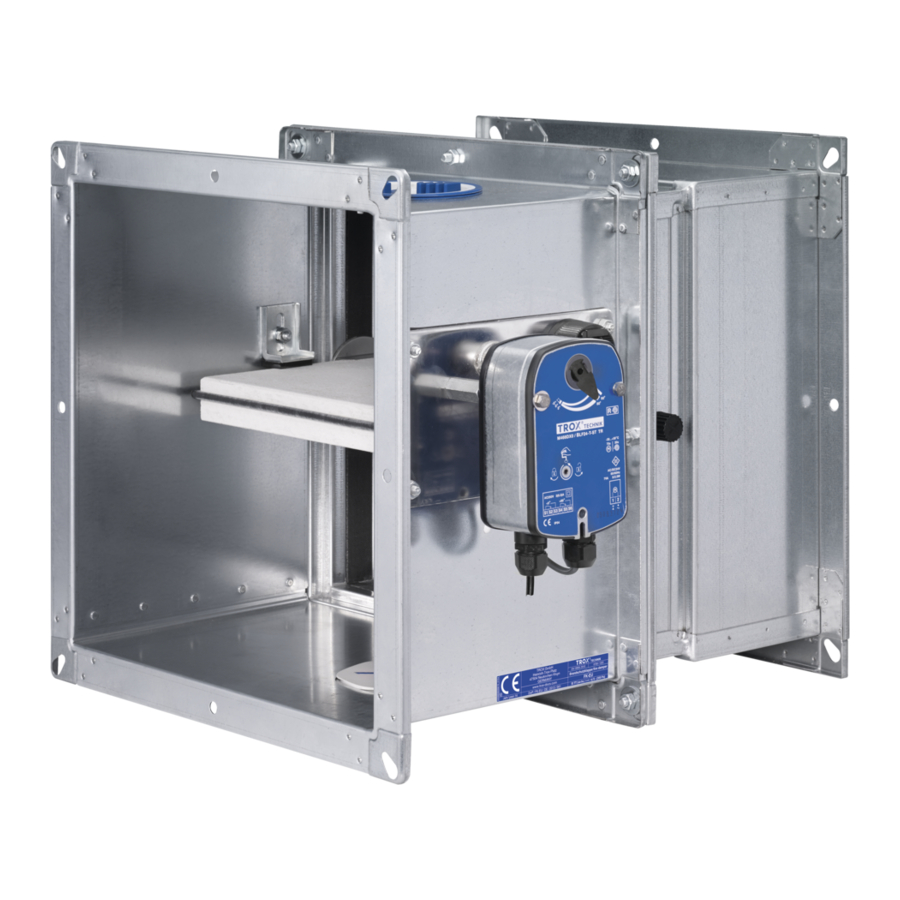
Fire dampers
Type FK-EU
For diverse applications
Rectangular fire damper for the isolation of duct penetrations between fire
compartments, for a variety of installation situations, available in many different sizes
and constructions
■
Nominal sizes 200 × 200 – 1500 × 800 mm, in increments of 1 mm
■
Low differential pressure and sound power level
■
Explosion-proof construction (ATEX) as an option
■
Can also be used as an air transfer damper
■
Optional stainless steel casing or powder-coated casing for increased
corrosion protection
■
Integration into the central BMS with TROXNETCOM
■
Universal installation options
Optional equipment and accessories
■
Electric actuator 24 V/230 V
■
Release temperature 72/95 °C
■
Duct smoke detectors
1
K4 – 1.1 – 1
Advertisement
Table of Contents

Subscribe to Our Youtube Channel
Related Manuals for Trox Technik FK-EU


Summary of Contents for Trox Technik FK-EU
- Page 1 FK-EU 1.1 – XFK-EU testregistrierung Fire dampers Type FK-EU FK-EU with fusible link for 72 °C or 95 °C CE compliant according to European regulations For diverse applications With TROXNETCOM as Rectangular fire damper for the isolation of duct penetrations between fire...
- Page 2 1.1 – 42 Quick sizing 1.1 – 43 Free area and resistance coefficient 1.1 – 45 Dimensions and weight – FK-EU 1.1 – 49 Dimensions and weight – FK-EU/.../Z4* 1.1 – 51 Dimensions and weight – FK-EU/.../ZEX* 1.1 – 52 Dimensions and weight –...
- Page 3 Fire dampers General information FK-EU FK-EU with fusible link FK-EU with spring return actuator Variants Product examples FK-EU with spring return actuator (explosion- FK-EU as air transfer damper proof) 06/2016 – DE/en K4 – 1.1 – 3...
- Page 4 General information FK-EU Application timber stud walls and half-timbered Description – TROX fire dampers of Type FK-EU, with CE constructions marking and declaration of performance, for – Installation kit for installation into lightweight the isolation of duct penetrations between fire...
- Page 5 Fire dampers General information FK-EU structure and cladding on one side: with Other components: installation kit ES – Damper blade shafts and driving linkage made – On the face of solid walls: with installation of stainless steel kit WA, for size L = 375 or 500 mm –...
- Page 6 72 °C or at 95 °C (use in warm air ventilation systems) by a fusible link. The release mechanism is accessible and can be tested from the outside. †† Schematic illustration of FK-EU with fusible link ② ③ ④ ⑤...
- Page 7 The spring return actuator is fitted with limit switches that can be used for capturing the damper blade position. Schematic illustration of FK-EU with spring return actuator ② ③ ④...
- Page 8 RedMax-15-BF TR ExPro-* –40 to 40 °C 10 m/s II 3G c IIC T6 * Release temperature: 72 °C ATEX certification Schematic illustration of FK-EU with spring return actuator, explosion-proof construction (e.g. ExMax-15-BF TR) ② ③ ④ ⑤ ⑥⑦ ①...
- Page 9 – Not to be connected to ducts in ventilation and the damper closes. Air transfer dampers consist of air conditioning systems an FK-EU fire damper, an RM-O-3-D duct smoke – Not to be used with accessories GM, GL100, detector with general building inspectorate WV or WE (Accessories 1) licence Z-78.6-125, a spring return actuator...
- Page 10 Fire dampers Correct use FK-EU Design information Never use the fire damper – Approved only for use in ventilation and air conditioning sytems – without specially approved attachments in – If the fire damper is installed in a solid wall,...
- Page 11 Fire dampers Correct use FK-EU 06/2016 – DE/en K4 – 1.1 – 11...
- Page 12 Fire dampers Correct use FK-EU K4 – 1.1 – 12 06/2016 – DE/en...
- Page 13 Fire dampers Correct use FK-EU 06/2016 – DE/en K4 – 1.1 – 13...
- Page 14 Fire dampers Correct use FK-EU K4 – 1.1 – 14 06/2016 – DE/en...
- Page 15 Fire dampers Correct use FK-EU Installation orientation with horizontal ducts Installation orientation ① ① Release mechanism (mechanical or spring return actuator) Installation orientation when used as an air transfer damper with horizontal ducts ① ② ① Duct smoke detector ② Spring return actuator 06/2016 – DE/en K4 – 1.1 – 15...
-
Page 16: Table Of Contents
FK – EU – 1 / DE / 600×400×500 / ES / SS / Z43 Type Accessories 1 FK-EU Fire damper No entry: none GM² Construction No entry: standard construction WV² Powder-coated casing, RAL 7001 WE² Stainless steel casing ES²... -
Page 17: No Entry: Standard Construction
Fire dampers Order code FK-EU FK-EU as air transfer damper Order code FK – EU – 1 / DE / 600×400×500 / ES / AA / Z43RM Type Accessories 2 FK-EU Air transfer damper Cover grilles on both ends Construction... - Page 18 – The fire damper and the installation kit must be installed and secured according to the operating and installation manual Installation kit for installation into solid non-load-bearing walls with flexible ceiling joint L [mm] Order code FK-EU with installation kit GM ① ② ③ ④ ⑤...
-
Page 19: Accessories 1
WA installation the WA installation manual manual. Installation kit for dry mortarless installation on the face of solid walls L [mm] Order code FK-EU with installation kit WA ③ ③ ② ① ② L = 37 5 / 50 0 ①... -
Page 20: Accessories 1
Accessories 1 Installation kit – for installation adjacent to solid walls FK-EU Application Materials and surfaces Description – Dry mortarless installation adjacent to solid – Installation kit made from special insulation walls requires an installation kit material and mineral wool strips / WV / –... - Page 21 Accessories 1 Installation kit – for installation adjacent to solid walls FK-EU FK-EU with installation kit WV ② ② ① x ≤ 26 0 ① ① ① ② ③ L = 50 0 ① ② Installation kit WV, consisting of: ① Installation kit...
- Page 22 Accessories 1 Installation kit – for installation remote from solid walls FK-EU Application Materials and surfaces Description – Dry mortarless installation remote from solid – Installation kit made from special insulation walls or ceiling slabs (below the ceiling, with material and mineral wool strips...
- Page 23 Accessories 1 Installation kit – for installation remote from solid walls FK-EU FK-EU with installation kit WE ② ② ③ ④ ② ③ L = 50 0 ① ② Installation kit WE, consisting of: ③ Calcium silicate boards (provided by others) ① Installation kit (provided by others) ④ Duct, galvanised steel (provided by others) ② Fixing elements 06/2016 – DE/en...
- Page 24 Installation kit for dry mortarless installation in lightweight partition walls, fire walls, safety par- tition walls and shaft walls L [mm] Order code FK-EU with installation kit ES ~ 9 0 ② ② ① ③...
- Page 25 GL100 / GL100¹ / walls with metal support structure, cladding on – 140 mm distance between two FK-EU fire both sides, and with flexible ceiling joint directly dampers of the same height and with ...
- Page 26 Accessories 1 Installation kit – installation with flexible ceiling joint FK-EU FK-EU with installation kit GL100 ⑤* ② B + 8 3 ⑤* ①* ③* ④* ③ ⑤ ④ L = 50 0 26 0 ⑤ ② ② ④ ③...
- Page 27 – Cover grilles both ends are approved in †† Germany only for Type FK fire dampers used Cover grille Cover grilles for FK-EU · FK-EU-1 · FK-EU-2 · FK-EU-7 / A0 / / 0A / Note: AA for FK-EU as air transfer damper...
- Page 28 Accessories 2 Cover grille FK-EU Cover grille The distance »a« between the open damper blade and the spigot should be approx. 50 mm. ① ② ① ① Cover grille, mesh aperture 10 mm × 10 mm, wire width 2 mm ② Extension piece Cover grille The distance »a« between the open damper blade and the spigot should be approx.
- Page 29 – The fixing holes in the spigots and extension manual. pieces match those in the fire damper flanges – Spigots are also available separately. Circular spigot for FK-EU · FK-EU-1 · FK-EU-2 · FK-EU-7 / R0 / / 0R / Operating side Installation side...
- Page 30 Accessories 2 Circular spigot FK-EU Circular spigot The distance »a« between the open damper blade and the spigot should be approx. 50 mm. ① ② ① ② ③ ③ ③ ① ② ④ ③ ③ ① ② ① ② ④...
- Page 31 – Flexible ducts can be used as an alternative manual. – For certain heights an extension piece may be †† required, see table Flexible connector for FK-EU · FK-EU-1 · FK-EU-2 · FK-EU-7 / S0 / / 0S / Operating side Installation side...
- Page 32 Accessories 2 Flexible connector FK-EU Flexible connector * flexible length ≥ 100 mm when installed The distance »a« between the open damper blade and the flexible connector should be approx. 50 mm. ① ② ① ① Flexible connector ② Extension piece K4 – 1.1 – 32 06/2016 – DE/en...
- Page 33 Accessories 2 Flexible connector FK-EU Flexible connector The distance »a« between the open damper blade and the flexible connector should be approx. 50 mm. ① ② ① ② ③ ③ ③ ① ② ③ ④ ③ ① ② ① ②...
- Page 34 Accessories 2 Extension piece FK-EU Application Materials and surfaces Description – Fire dampers ordered with flexible connector, – Extension pieces made of galvanised sheet cover grille or circular spigot are supplied steel (and powder-coated silver grey, including extension piece. RAL 7001, when used with powder-coated (1) – Extension pieces of 120 mm or 260 mm length and stainless steel (2) dampers) are also available separately Note For further information relevant to design, in ...
- Page 35 Accessories 2 Extension piece FK-EU Extension piece The distance »a« between the open damper blade and the flexible connector should be ① ② ① ② approx. 50 mm. ③ ③ L = 375 / 500 L = 375 / 500 ①...
-
Page 36: Attachments
Limit switch for damper blade position OPEN Limit switches for damper blade positions CLOSED and OPEN Order code detail FK-EU with limit switch (explosion-proof) Description – According to declaration of conformity TÜV 11 ATEX 085420 X explosion-proof limit switches with volt-free contacts can indicate the damper blade position. - Page 37 Attachments Limit switch FK-EU ATEX areas of application for the FK-EU Release mechanism Marking Ambient temperature Maximum airflow velocity Fusible link II 2D c T80 °C/II 2G c IIC T6 –40 to 40 °C 8 m/s Fusible link and limit switch II 2D c T80 °C/II 2G c IIC T6 –20 to 40 °C 8 m/s ATEX certification 06/2016 – DE/en K4 – 1.1 – 37...
- Page 38 Attachments Spring return actuator FK-EU FK-EU with spring return actuator indication (OPEN and CLOSED) Description – An open/close actuator allows for the remote – The connecting cables of the 24 V spring return control of the fire damper and/or release by a actuator are fitted with plugs, which ensure suitable duct smoke detector quick and easy connection to the TROX AS-i – If the supply voltage fails, or with thermoelectric bus system release, the damper closes (power off to close) – ...
- Page 39 Attachments Spring return actuator FK-EU ATEX areas of application Attachments Release mechanism Marking Ambient temperature ExMax-15-BF TR ExPro-TT II 2D c T80 °C II 2G c IIC T6 –40 to 40 °C RedMax-15-BF TR ExPro-TT II 3D c T80 °C II 3G c IIC T6 –40 to 40 °C ATEX certification 06/2016 – DE/en K4 – 1.1 – 39...
- Page 40 Z-6.50-2031 * The 24 V DC construction includes a voltage To prevent smoke from spreading in buildings, it is monitoring module extremely important that the smoke is detected at an early stage. A duct smoke detector RM-O-3-D can be used to activate FK-EU fire dampers with a spring return actuator. The duct smoke detector operates on the principle of light scattering and detects the smoke regardless of its temperature so that the fire dampers can be closed before the release temperature is reached.
- Page 41 Attachments TROXNETCOM FK-EU FK-EU with spring return actuator and signal for up to two fire dampers Description TROXNETCOM – LON-WA1/B2-AD: Connection box for – Fire dampers with a 24 V spring return actuator connecting the second fire damper with and the modules described here as 24 V DC supply voltage to LON-WA1/B2-AD attachments form a functional unit ready for – LON-WA17B2-AD230: Connection box with automatic operation. integral 230/24 V power supply unit for the – The components are factory assembled and...
- Page 42 Attachments Duct smoke detectors FK-EU General Application Description – To prevent smoke from spreading in buildings, RM-O-3-D: it is extremely important that the smoke is – Duct smoke detector for fire dampers and detected at an early stage. smoke protection dampers – Duct smoke detectors that operate on the – General building inspectorate licence Z-78.6- ...
- Page 43 Fire dampers Quick sizing FK-EU Volume flow rate [m³/h] at differential pressure Δp < 35 Pa H [mm] B [mm] 1152 1404 1620 1116 1260 1296 1620 1944 2268 1584 1800 1188 1476 1764 2052 1476 1692 1188 1620 2052...
- Page 44 Fire dampers Quick sizing FK-EU Volume flow rate [l/s] at differential pressure Δp < 35 Pa H [mm] B [mm] 1020 1120 1210 1310 1410 1020 1100 1180 1110 1100 1220 1340 1450 1570 1680 1000 1090 1190 1280 1380...
- Page 45 Fire dampers Free area and resistance coefficient FK-EU B [mm] H [mm] Parameters A [m²] 0.02 0.027 0.034 0.041 0.048 0.055 0.062 0.069 0.076 0.083 ζ 1.12 0.94 0.77 0.71 0.65 0.59 0.53 0.53 0.47 0.47 A [m²] 0.029 0.039 0.048...
- Page 46 Fire dampers Free area and resistance coefficient FK-EU B [mm] H [mm] Parameters 1000 1100 1200 1300 1400 1500 A [m²] 0.09 0.097 0.104 0.084 0.094 0.104 0.114 0.124 0.134 0.144 ζ 0.41 0.41 0.41 2.18 2.18 2.18 2.18 2.18 A [m²]...
- Page 47 Fire dampers Free area and resistance coefficient FK-EU B [mm] H [mm] Parameters A [m²] 0.108 0.131 0.153 0.176 0.198 0.221 0.243 0.266 0.288 ζ 0.78 0.69 0.64 0.59 0.54 0.49 0.49 0.49 0.44 A [m²] 0.12 0.145 0.17 0.195 0.22...
- Page 48 Fire dampers Free area and resistance coefficient FK-EU B [mm] H [mm] Parameters 1000 1100 1200 1300 1400 1500 A [m²] 0.311 0.333 0.378 0.423 0.468 0.513 0.558 0.603 0.648 ζ 0.44 0.44 0.39 0.39 0.39 0.39 0.39 0.34 0.34 A [m²]...
- Page 49 Fire dampers Dimensions and weight – FK-EU FK-EU FK-EU with fusible link Dimensions ① FK-EU with fusible link L = 375 oder 500 ~ 175 W: 115 mm ① Keep clear to provide access to the release mechanism Weights 06/2016 – DE/en K4 – 1.1 – 49...
- Page 50 Fire dampers Dimensions and weight – FK-EU FK-EU Weights 1000 1100 1200 1300 1400 1500 K4 – 1.1 – 50 06/2016 – DE/en...
- Page 51 Fire dampers Dimensions and weight – FK-EU/.../Z4* FK-EU FK-EU with spring return actuator (FK-EU/.../Z4*) Dimensions ① FK-EU with spring return actuator ~ 100 L = 375 oder 500 ~ 175 W: 115 mm ① Keep clear to provide access to the spring return actuator Weights Weights 1000 1100 1200 1300 1400 1500 06/2016 – DE/en K4 – 1.1 – 51...
- Page 52 Fire dampers Dimensions and weight – FK-EU/.../ZEX* FK-EU FK-EU with explosion-proof actuator (FK-EU/.../ZEX1* and ZEX3*) Dimensions ① FK-EU with spring return actuator (explosion-proof) ~ 200 L = 375 oder 500 ~ 220 W: 115 mm ① Keep clear to provide access to the spring return actuator Weights Weights 1000 1100 1200 1300 1400 1500 K4 – 1.1 – 52 06/2016 –...
- Page 53 Fire dampers Dimensions and weight – FK-EU/.../Z**RM FK-EU FK-EU as air transfer damper (FK-EU/.../Z**RM) Dimensions ① 120 / 260 ① FK-EU as air transfer damper ~ 100 L = 500 ~ 175 W: 115 mm ① Keep clear to provide access to the duct smoke detector and to the spring return actuator Weights Weights 1000 1100 1200 1300 1400 1500 06/2016 –...
- Page 54 Fire dampers Dimensions – Duct connection FK-EU Flange – uneven number of holes Dimensions 300 300 ∅10 17,5 Flange – even number of holes 300 300 ∅10 17,5 Dimensions [mm] 1100 1300 1500 B or H 1000 1200 1400 No. of holes horizontally (B)* No.
- Page 55 Fire dampers Specification text FK-EU Rectangular or square fire dampers for the Special characteristics Description isolation of duct penetrations between fire – Declaration of performance according to compartments; two inspection access panels, Construction Products Regulation This specification text Ø110 mm. – Classification to EN 13501-3, up to EI 180 describes the general Tested for fire resistance properties to EN 1366-2, , i ↔ o) S properties of the product. with CE marking and declaration of performance – Building inspectorate licence Z-56.4212-991 Texts for variants can be according to the Construction Products ...
- Page 56 Fire dampers Specification text FK-EU Type Accessories 1 Order options FK-EU Fire damper No entry: none GM² Construction No entry: standard construction WV² 1 Powder-coated casing, RAL 7001 WE² 2 Stainless steel casing ES² 7 Coated damper blade GL100²ʼ³ 1 – 7 Powder-coated casing, RAL 7001, and coated damper blade Accessories 2 2 – 7 Stainless steel casing and coated ...
- Page 57 Fire dampers Specification text FK-EU as air transfer damper Square or rectangular air transfer dampers with Special characteristics Description two inspection access panels, Ø110 mm, for – General building inspectorate licence Z-6.50- shutting off air transfer openings in fire-resistant 2031 from the DIBt This specification text walls or ceilings, to prevent the penetration of – Declaration of performance according to describes the general heat, flames and smoke for at least 90 minutes. Construction Products Regulation properties of the product.
- Page 58 Fire dampers Specification text FK-EU as air transfer damper Type Accessories 2 Order options FK-EU Air transfer damper AA Cover grilles on both ends Construction Attachments No entry: standard construction Z43RM, Z45RM, ZA12 1 Powder-coated casing, RAL 7001 2 Stainless steel casing ¹WA can be combined only with accessory A0 (cover grille on the operating side). A 7 Coated damper blade cover grille for the installation side has 1 – 7 Powder-coated casing, RAL 7001, and to be ordered separately or has to be coated damper blade provided by others.
Need help?
Do you have a question about the FK-EU and is the answer not in the manual?
Questions and answers