Table of Contents
Advertisement
Quick Links
Advertisement
Table of Contents

Related Manuals for Kahn Optisure Remote


Summary of Contents for Kahn Optisure Remote
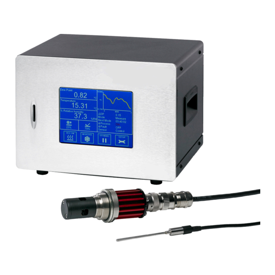
- Page 1 Optisure Remote Chilled Mirror Hygrometer User’s Manual March 2018...
- Page 2 Optisure Remote...
-
Page 3: Table Of Contents
Optisure Remote User’s Manual Contents Safety ..........................v Electrical Safety ......................v Pressure Safety ......................v Repair ........................v Calibration ........................v Abbreviations ........................vi Warnings ..........................vi INTRODUCTION ....................1 INSTALLATION ....................2 Safety ........................ 2 Unpacking the Instrument ................... 2 Operating Requirements ..................3 2.3.1... - Page 4 Optisure Remote User’s Manual Tables Table 1 Front Panel ....................4 Table 2 Rear Panel Controls ..................5 Table 3 Main Screen Layout ................... 15 Table 4 Operational Status Display ................. 17 Table 5 Sensor Status Display ................17 Table 6 DCC Menu ....................18 Table 7 Logging Menu ...................
-
Page 5: Safety
The instrument must be repaired by the manufacturer. Please contact Kahn Instruments at parts. service@kahn.com. Calibration The recommended calibration interval for the Optisure Remote is one year, unless otherwise specified by Kahn Instruments. The instrument should be returned to Kahn (please contact parts.service@ kahn.com). -
Page 6: Abbreviations
Optisure Remote User’s Manual Abbreviations The following abbreviations are used in this manual: Dynamic Contamination Correction FAST Frost Assurance System Technology MAXCOOL Maximum Sensor Cooling alternating current pressure unit (atmosphere) pressure unit (=100 kP or 0.987 atm) °C degrees Celsius °F... - Page 7 Optisure Remote User’s Manual NOTES Kahn Instruments...
-
Page 8: Introduction
INTRODUCTION INTRODUCTION The Optisure Remote Hygrometer is a high precision instrument used for the measurement of moisture content in air and other gases. Relative humidity and other calculated parameters based on dew point, pressure and temperature of the sample gas can also be displayed. -
Page 9: Installation
Optics cleaning kit • USB communications cable • Remote Pt100 temperature probe • IEC power cable • Sensor cable • Dew-point sensor • Pressure transducer and cable (optional) If there are any shortages please notify Kahn Instruments immediately (hygros@kahn.com). March 2018... -
Page 10: Operating Requirements
2.3.1 Environmental Requirements The operational range of the Optisure Remote sensor is dependant on the temperature of the environment in which it is installed. The sensor is able to measure dew points down to 90°F (60°C) below ambient temperature, and anywhere up to (but not including) the point of condensation. -
Page 11: Rear Panel
Optisure Remote User’s Manual INSTALLATION Name Description Displays measured values and enables the user to control the Touch Screen operation of the instrument. See section 3 for information about Display the touch screen and menu system. Takes an SD card used to store logged data. See section 3.2.2 SD Slot for further information on how to use data logging. -
Page 12: Rear Panel Controls
Optisure Remote User’s Manual INSTALLATION Name Description Universal power input 85 to 264 V AC, 47/63 Hz Fuse - T2.5A, Glass, 20 x 5mm Power Socket Features integrated power ON/OFF switch Used for connecting the chilled mirror sensor to the Sensor Connector instrument via the sensor cable. -
Page 13: Rear Panel Connections
Optisure Remote User’s Manual INSTALLATION Rear Panel Connections These tasks should be undertaken only by competent personnel. All the connections to the rear panel are electrical connections. Exercise due caution, particularly when connecting to external alarm circuits which could be at high DANGER potential. -
Page 14: Analog Output Connections
Optisure Remote User’s Manual INSTALLATION 2.5.2 Analog Output Connections The three analog outputs can be configured to represent any of the directly measured or calculated output parameters. They are provided as 2-wire signals from a 6-way connector located on the rear panel of the instrument. -
Page 15: Alarm Output Connections
Optisure Remote User’s Manual INSTALLATION For each output: Remove the terminal block fitted into the analog output socket. Strip back the wire for the common (black) connection to the output, exposing approximately 0.25" (6mm) wire insert the wire into the COM1 terminal way and screw into the block. -
Page 16: Figure 5 Alarm Output Connectors
Optisure Remote User’s Manual INSTALLATION WARNING: Alarm leads MUST be potential free when wiring to the connector block. DANGER Electric Shock Risk Alarm Output Connectors Figure 5 For each output: Strip back the wire for the common (black) connection to the... -
Page 17: Dew-Point Sensor Connection
Optisure Remote User’s Manual INSTALLATION 2.5.4 Dew-Point Sensor Connection The dew-point sensor contains the optical system and the chilled mirror. It is fitted with an M12 connector to allow easy and secure connection to the instrument using the supplied sensor cable. -
Page 18: Usb Communications Port Connector
Optisure Remote User’s Manual INSTALLATION 2.5.6 USB Communications Port Connector The instrument features a USB port for communication with the Application Software. The appropriate cable will be supplied with the instrument. Check the orientation of the connector and gently push it into the socket labelled (see Figure 8) . -
Page 19: Rs232/485 Port (Optional)
Optisure Remote User’s Manual INSTALLATION 2.5.8 RS232/485 Port (Optional) The instrument features an optional RS232/485 port for communication with the application software. This is designed to be used with a standard 9-pin D-sub connector. Check the orientation of the connector and gently push it into the socket labelled RS232 or RS485, and tighten the retaining screws. -
Page 20: Remote Pressure Transducer (Optional)
Optisure Remote User’s Manual INSTALLATION 2.5.9 Remote Pressure Transducer (Optional) Rotate the body of the pressure transducer connector until it locates in the socket labelled PRESSURE TRANSDUCER. Push the connector into the socket until it locks. NOTE: Do not attempt to force it into the socket. -
Page 21: User Interface
Optisure Remote User’s Manual OPERATION USER INTERFACE All measurement results can be read, and all common parameters adjusted, by the 5.7” touch screen display. All functionality available through the touch screen is present when running the Michell Application Software. The Optisure offers 4 possible interfaces to connect to a PC or network: •... - Page 22 Optisure Remote User’s Manual OPERATION Name Description Customizable Readouts Display measured and calculated parameters. See section 3.1.2 for additional information. Sensor Status Display Displays both thermo-electric cooler (TEC) drive and optical signal condition. See section 3.1.5 for additional information. Trend Graph Plots measured dew point over time.
-
Page 23: Figure 13 Menu Structure
Optisure Remote User’s Manual OPERATION 3.1.3 Menu Structure DISPLAY RESET OUTPUT SETPOINT PERIOD INTERVAL HOLD OPTICS HOLD LOGGING INTERVAL FILENAME STATUS OUTPUT OUTPUT OUTPUT PARAMETER MINIUMUM MAXIMUM SELECT TYPE ALARM PARAMETER SETPOINT DISPLAY PRIMARY PRESSURE FAST LANGUAGE STABILITY BRIGHTNESS RESOLUTION... -
Page 24: Table 4 Operational Status Display
Optisure Remote User’s Manual OPERATION 3.1.4 Operational Status Display ΔDP Shows the total change in measured dew point over the time base of the trend graph Mode Shows current operation mode: Measure, Standby, DCC, FAST, Max Cool, Data Hold Next Mode... -
Page 25: Dcc Menu
Optisure Remote User’s Manual OPERATION Display Hold Also holds measured and calculated values shown on the display throughout the course of Data Hold Available input: Off, On Setpoint Mirror heating temperature during DCC, relative to last measured dew point Available input: 10 to 40... -
Page 26: Logging Menu
Optisure Remote User’s Manual OPERATION Interval Changes the interval at which data is recorded Input format: mm:ss Available input: 0:05 to 10:00 SD Status Indicates status of inserted SD card: Indicator No SD card inserted Ready to log Initialising card... -
Page 27: Outputs Menu
Optisure Remote User’s Manual OPERATION Output select Selects the output to be adjusted Available input: Output 1, 2 or 3 Output type Selects the type of analog output signal to use Available input: 4-20mA, 0-20mA, 0-1V Parameter The parameter used to control the elected output... -
Page 28: Display Menu
Allows adjustment of current date and time, used for time stamps on logged data. 3.2.7 About (Network Settings) When the optional Ethernet card is installed in the Optisure Remote, the Network Settings menu is accessible via the About screen. Network settings... -
Page 29: Operating Cycle
Optisure Remote User’s Manual OPERATION OPERATION Operating Cycle Figure 19 Typical Operating Cycle At initial switch-on, the instrument enters a DCC cycle for 2 minutes. During this time the mirror is heated above the prevailing dew point to insure that all condensate is driven off the surface of the mirror. -
Page 30: Operating Guide
4.2.1 Description Once the Optisure Remote has been powered on and has carried out its’ initial DCC, it will attempt to find the dew point. In order to measure the dew point a Chilled Mirror hygrometer must control a thin film of condensed water or ice on the mirror. -
Page 31: Figure 20 Room Measurement Example
If this is the case, then a guard fitted over the sensor can mitigate the effects of excessive gas speed by dissipating the sample throughout its’ surface area. An appropriate guard can be purchased from Kahn Instruments. March 2018... -
Page 32: Figure 21 Sample Block
Insure that the sensor is positioned in an environment of known pressure. You can then either enter this pressure into the Optisure Remote via the Application Software, or connect a pressure sensor directly to the point of measurement (see section 2.5.9). -
Page 33: Figure 22 Material Permeability Comparison
Optisure Remote User’s Manual OPERATION Transpiration and Sampling Materials - 20 - 30 nylon - 40 - 50 copper - 60 polyethylene - 70 PTFE nickel stainless steel Time (hours) Material permeability comparison Figure 22 All materials are permeable to water vapor, as the water molecule is extremely small compared to the structure of solids, even when compared to the crystalline structure of metals. -
Page 34: Figure 23 Formation Of Condensation
Optisure Remote User’s Manual OPERATION valves trap moisture, so using the simplest sampling arrangement possible will reduce the time it takes for the sample system to dry out when purged with dry gas. Over a long tubing run, water will inevitably migrate into any line, and the effects of adsorption and desorption will become more apparent. - Page 35 Optisure Remote User’s Manual OPERATION An inadequate flow rate can: • Accentuate adsorption and desorption effects on the gas passing through the sampling system. • Allow pockets of wet gas to remain undisturbed in a complex sampling system, which will then gradually be released into the sample flow.
-
Page 36: First Time Operation
Optisure Remote User’s Manual OPERATION First Time Operation Before using the instrument, please read through the Installation, Operation and Maintenance sections of this manual. This instruction assumes that all recommendations within these sections have been followed, and that the control unit and sensors are physically installed and all electrical connections complete. -
Page 37: Frost Assurance Technology (Fast)
32°F (0°C) taken over water will read approximately 10% lower than the same measurement taken over ice. Following DCC, the Optisure Remote makes an initial dew point measurement. If the initial measurement is between +26°F (-3°C) and -40°F/C then the mirror is driven down to below -40°C to insure the formation of ice on the mirror surface. -
Page 38: Minimum Measurable Dew Points
Optisure Remote User’s Manual OPERATION Log files are saved in CSV (comma separated value) format. This allows them to be imported easily into Excel or other programs for charting and trend analysis. To set-up data logging refer to Section 3.2.2. -
Page 39: Maintenance
Optisure Remote User’s Manual MAINTENANCE MAINTENANCE There are few user-serviceable parts on the Optisure Remote. These include cleaning the mirror in the sensor and the removal and replacement of the AC power supply fuse. Safety This equipment operates from power supply voltages that can be lethal and at pressures (depending upon application) that could cause injury. -
Page 40: Sensor Mirror Cleaning
Optisure Remote User’s Manual MAINTENANCE Locate the fuse carrier and pull it out of the connector housing. A small screwdriver inserted under the lip may be useful in order to lever it out. Replace the fuse cartridge. NOTE: It is essential that a fuse of the correct type and rating is installed in the instrument (T2.5A 20 x... -
Page 41: Calibration
(refer to Section 3.2.1). A calibration certificate bearing a four point calibration is issued with each instrument. If required, an option is available to add further specific calibration points. Contact Kahn Instruments for further information (see www.michell.com for contact details). -
Page 42: Appendix A Technical Specifications
Optisure Remote User’s Manual APPENDIX A Appendix A Technical Specifications Kahn Instruments... - Page 43 ±0.18°F (±0.1°C ) Cable Length 6.6ft (2m) (820ft (250m) max) Optional Remote Pressure Sensor Measurement Range 0 to 377 psia (0 to 25 bara) Accuracy 0.25% Full Scale **Recommended for special applications only. Consult Kahn Instruments before ordering. March 2018...
- Page 44 9.8, 16.4 or 32.8ft (3, 5 or 10m) General Storage Temperature -40 to +140°F (-40 to +60°C) Detection System Single optics detection system with auto adjustment 4-point traceable in-house calibration as standard Calibration UKAS accredited calibrations optional - please consult Kahn Instruments Kahn Instruments...
-
Page 45: Dimensions
Optisure Remote User’s Manual APPENDIX A Dimensions 257.0 mm 10.118 ins 215.0 mm 8.465 ins Figure 28 Optisure Remote Dimensions 74mm (2.91”) with sintered guard (optional) 3.5mm (0.14”) Dowty Bonded Seal M36x1.5 - 6g THIS DOCUMENT IS THE PROPERTY OF MICHELL... - Page 46 Optisure Remote User’s Manual APPENDIX B Appendix B Kahn Instruments...
-
Page 47: Appendix B Application Software
Optisure Remote User’s Manual Application Software The Optisure Remote features a USB interface for communication with the application software. A copy of the application software is supplied on a CD with the instrument. The application software is also available from the support section of the Kahn Instruments' website at: http://www.michell.com/uk/support/sware-downloads.htm... - Page 48 Optisure Remote User’s Manual 2.1. USB Communication Connect the Optisure Remote to the PC using the supplied USB cable. Windows will recognize the instrument and automatically install the relevant drivers. If the driver installation has been successful then the Windows Device Manager Screen will list the following driver (see Figure...
- Page 49 Optisure Remote User’s Manual Data Acquisition or Edit Variables Mode Once communication has been established, the Options Screen is displayed. Options Screen March 2018...
- Page 50 Optisure Remote User’s Manual Data Acquisition This mode of operation allows all measured instrument parameters to be graphed and logged in real time. Log le and plot Instrument Acquisition interval tools mode buttons buttons Instrument readings Chart Chart option buttons...
- Page 51 Optisure Remote User’s Manual Instrument Readings and Status This area displays all measured instrument parameters and shows the status of the Fault, Process and Sensor Cooler Alarms. Graph Controls Name Description Plot Automatically advances the graph as new data is acquired...
- Page 52 Optisure Remote User’s Manual Variable Edit The variable edit mode allows the instrument configuration to be changed through the application software. On launch, it will automatically read and display the current values of each of the instrument variables. NOTE: The variables are not periodically updated on-screen. To obtain up-to- date values, click the Read button.
- Page 53 Optisure Remote User’s Manual Optisure Series Variables Editor Screen March 2018...
- Page 54 http://www.kahn.com...
Need help?
Do you have a question about the Optisure Remote and is the answer not in the manual?
Questions and answers