
Subscribe to Our Youtube Channel
Related Manuals for Teldat ATLAS 50


Summary of Contents for Teldat ATLAS 50
- Page 1 Manual Teldat S.A. ATLAS 50 Installation Manual Copyright© Teldat-DM696-I Version 3.1 7/2015 Teldat S.A. ATLAS 50...
- Page 2 This publication is subject to change. Teldat S.A. offers no warranty whatsoever for information contained in this manual. Teldat S.A. is not liable for any direct, indirect, collateral, consequential or any other damage connected to the deliv- ery, supply or use of this manual.
-
Page 3: Table Of Contents
Recycling and the Environment ......Translated Safety Warnings ......ATLAS 50... - Page 4 Table of Contents Teldat S.A. ATLAS 50...
-
Page 5: I Important Information
Furthermore, it is crucial to avoid any kind of contact between the device components and necklaces, bracelets, rings, ties, etc. ATLAS 50... -
Page 6: Installing The Router
1.1 Introduction The ATLAS 50 aims at meeting the voice, video and data needs of small-sized companies and offices. It is a modu- lar device incorporating encryption hardware and designed with network convergence in mind, as it supports IP Tele- phony and the possibility to encode video. -
Page 7: Power Source Connection
For subsequent connection of the power source to the main electricity supply, use the grounded cable provided for this purpose. 1.2.2 Data Connection The ATLAS 50 router family has the following connectors. Depending on the model. some of these connectors may not be available: FE 0, FE 1: FastEthernet Interfaces. - Page 8 Passive-Bus terminal resistances The ATLAS 50 has 2 internal jumpers to configure the S-BUS terminal resistances. To access the jumpers (P1 and P2), you need to open the open the lid or top of the device. The jumpers are located next to the Power connector (S1) and the BRI (CN1) connector.
- Page 9 Sole or last terminal Fig. 7: • Intermediate position on the ISDN “S” bus The P1 and P2 jumpers must be off (without terminal resistance) if the router occupies an intermediate position on the ISDN “S” bus. ATLAS 50...
- Page 10 1.2.2.3 Connecting for configuration The ATLAS 50 router has a RJ45 female connector on the front panel referred to as “ CONF.” , which provides ac- cess to the device local console. In order to configure this, you must connect the “ CONF.” port to an asynchronous terminal (or to a PC with terminal emulation).
-
Page 11: Meaning Of The Leds
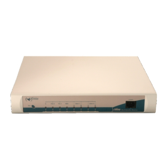
1 Installing the Router Teldat S.A. Connecting for configuration Fig. 9: 1.3 Meaning of the LEDs ATLAS 50 Router Front Panel Fig. 10: Power-on indicator. It lights up when connected to the power. Router operations OFF: System stopped. GREEN: System initialized and operating. -
Page 12: Programming The Microswitches
1.4 Programming the microswitches The ATLAS 50 router has a block of 8 available micro-switches, located on the underside of the device, which are used for maintenance and test tasks. In this case, they are only used to load the default configuration. -
Page 13: Pmc-Pci Cards
This way, th saved configuration will run next time you restart the device. 1.5 PMC-PCI Cards The ATLAS 50 features and interfaces can be amplified by inserting PMC boards (PCI mezzanine card). In order to correctly insert the card, please follow the steps given below. -
Page 14: Procedure To Install Pmc Cards
If the problem per- sists, please contact your usual supplier. (11) Connect a terminal to the console and check that the device detects the PMC board. ************************************************** ******************* Router Teldat **************** ************************************************** BOOT CODE VERSION: 01.06 2 2006 10:22:22... - Page 15 (Subs. Vendor: 0x0000, Subs. Device: 0x0000) Slot 1 - PCI device: CardBus bridge (Bus: 0, Device: 10, Function: 0) (Subs. Vendor: 0x0000, Subs. Device: 0x0000) Current production date: 00 00 Current software license: 12 15 Current serial number: 550/05646 BIOS MAC Add: 00-a0-26-a0-16-0e ATLAS 50...
-
Page 16: Appendix A Technical Information
A.2 Updating the software The ATLAS 50 router can be updated to new releases. Please contact your distributor for further details on new re- leases. The software required to update Teldat routers is supplied in a format known as distribution. This consists of a single file that contains all the files needed to update your device, as well as in-depth information on the contents of the files. -
Page 17: Connectors
Technical Information Teldat S.A. A.3 Connectors A.3.1 LAN (FE x) Connector RJ45 PIN RJ45 LAN Tx+(input) Tx-(input) Rx+(output) Rx-(output) A.3.2 BRI Connector RJ45 PIN ISDN RJ45 ISDN Tx+(output) Rx+(input) Rx-(input) Tx-(output) A.3.3 ANT Connectors Internal RF in/out External ATLAS 50... -
Page 18: Configuration Connector
Please see the manual on Wireless LAN SPEED Please see the manual on Wireless LAN CONNECTOR 2 RF * Depending on the model ISDN Interface* ACCESS Basic 2B+D SPEED 2 x 64 Kbps (Channels B) CONNECTOR RJ45 female ATLAS 50... - Page 19 LENGTH x WIDTH x HEIGHT 220 x 220 x 30 mm WEIGHT 1 kg Environmental Specifications AMBIENT TEMPERATURE ON: 5º to 45 ºC. OFF: -20º to 60 ºC. RELATIVE HUMIDITY ON: 8 % to 85 %. OFF: 5 % to 90 %. ATLAS 50...
-
Page 20: Appendix B Safety Information
B.1 Recycling and the Environment Please do not, under any circumstances, throw away any ATLAS 50 with normal domestic waste. Ask your local town hall for information on how to correctly dispose of them in order to protect the environment against e-waste. Al- ways respect the current laws regarding waste material. -
Page 21: Translated Safety Warnings
Safety information Teldat S.A. B.2 Translated Safety Warnings Connections ATLAS 50...
Need help?
Do you have a question about the ATLAS 50 and is the answer not in the manual?
Questions and answers