Table of Contents
Advertisement
Quick Links
Advertisement
Table of Contents

Related Manuals for Westermo Pilot Wire RPW600M


Summary of Contents for Westermo Pilot Wire RPW600M
- Page 1 User Guide 6621-2260 Pilot wire modem RPW600M / RPW600F...
-
Page 2: Legal Information
Legal information The contents of this document are provided “as is”. Except as required by applicable law, no warranties of any kind, either express or implied, including, but not limited to, the implied warranties of merchantability and fitness for a particular purpose, are made in relation to the accuracy and reliability or contents of this document. -
Page 3: Before Installation
Safety Before installation: Read the user guide completely and gather all information on the unit. Make sure that you understand it fully. Check that your application does not exceed the safe operating specifications for this unit. This unit should only be installed by qualified personnel. This unit should be built-in to an apparatus cabinet, or similar, where access is restricted to service personnel only. -
Page 4: Maintenance
Note. Fibre Optic Handling Fibre optic equipment needs special treatment. It is very sensitive to dust and dirt. If the fibre will be disconnected from the modem the protective hood on the transmitter/ receiver must be connected. The protective hood must be kept on during transportation. The fibre optic cable must also be handled the same way. - Page 5 General RPW600 Pilot Wire modems are used with RED615 line differential protection and control IEDs to enable the galvanic protection communication connection over twisted pair media, better known as Pilot Wire in the area of line differential protection applications. Two different variants of the RPW600 modems are available, a master (RPW600M) and a follower (RPW600F) which always are needed to be used as counterparts in pilot wire communication link.
-
Page 6: Environmental Conditions
Environmental conditions Phenomena Test Description Test levels Temperature Operating –20 to +55ºC Storage & Transport –40 to +85C Humidity Operating 5 to 95% relative humidity Storage & Transport 5 to 95% relative humidity Altitude Operating Up to 2 000 m / 70 kPa Enclosure UL 94 Zink... - Page 7 Type tests emission Environmental Basic Environment phenomena Standard Radiated emission EN 55022 EN 55022 Enclosure Class A 30 MHz – 230 MHz 230 MHz – 1000 MHz Conducted emission EN 55022 EN 55022 DC power port Class A 0.15 – 30 MHz Type tests temperature Environmental Standard...
-
Page 8: Interface Specifications
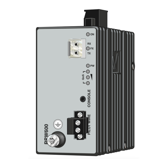
Interface specifications Power Rated voltage 24 to 110 VDC Operating voltage 19,2 to 154 VDC Rated current 200 mA @ 24 VDC 50 mA @ 110 VDC Rated frequency Inrush current, I2t 0.11 A²s @ 48 VDC Startup current* 0.2 Apeak @ 24VDC Polarity Reverse polarity protected Isolation to... - Page 9 Power* Top view Position Description Product marking Common Common + Voltage + Voltage – This unit is supplied with one power module and with redundant power input connections. Ethernet FX Position Direction* Description Receiver LED indicators Optical input (see page 10) Transmitter Optical output Direction relative this unit.
-
Page 10: Led Indicators
LED indicators Status Description Unit has no power GREEN Internal power ok The unit is booting Inactive link Fibre link GREEN Active link indication GREEN FLASH Data is transmitted Inactive link Pilot wire link GREEN Active link indication GREEN FLASH Link negotiation Quality of LED 1... - Page 11 Diagnostic QoS indication The QoS indication on the front of the unit gives an indication of the pilot wire link sta- tus. If indication shows weak link it is recommended to improve the pilot wire characteristic. A weak link can be unstable and result in data transmission losses. RPW-diagnostic tool connection The RPW-diagnostic tool, which is part of the RPW- diagnostic kit, can be used for more advanced diagnostic...
-
Page 12: Earth Connection
Mounting This unit should be mounted on 35 mm DIN- rail, which is horizontally mounted inside an apparatus cabinet or similar. Snap on mounting, see figure. Earth connection For correct function the ground connection on the unit needs to be properly connected to a solid ground. - Page 16 Made for ABB by Westermo Teleindustri AB ABB Oy Distribution Automation P.O. Box 699 FI-65101 VAASA, Finland Phone +358 10 22 11 Fax +358 10 22 41094 REV.A 6621-2260 2010-07...
Need help?
Do you have a question about the Pilot Wire RPW600M and is the answer not in the manual?
Questions and answers