
Related Manuals for Westermo ODW-710-F2


Summary of Contents for Westermo ODW-710-F2
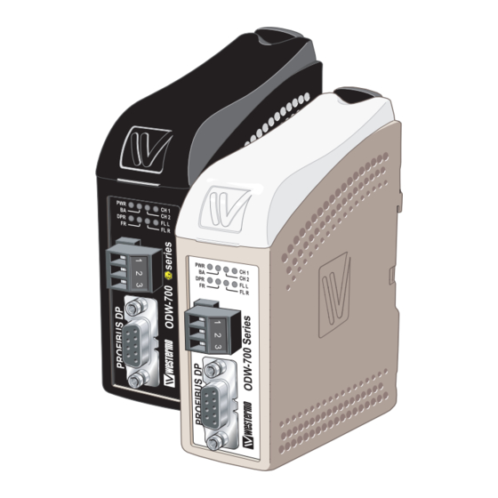
- Page 1 User Guide 6651-2211 ODW-710-F2 Fibre Optic Modem Industrial Converter PROFIBUS DP to Fibre Optic Link. Point to Point applications www.westermo.com...
-
Page 2: Legal Information
Under no circumstances shall Westermo be responsible for any loss of data or income or any special, incidental, and consequential or indirect damages howsoever caused. -
Page 3: Before Installation
Do not use or store the unit in dusty, dirty areas. Connectors as well as other mechanical parts may be damaged. If the unit is not working properly, contact the place of purchase, nearest Westermo distributor office, or Westermo Tech support. -
Page 4: Maintenance
EN 60950-1, IT equipment** ATEX** EN 60079-0 and EN 60079-15 * Applicable for ODW-710-F2 only ** Applicable for ODW-710-F2 Ex only FCC Part 15.105 This equipment has been tested and found to comply with the limits for a Class A Notice: digital device, pursuant to Part 15 of the FCC Rules. - Page 5 ATEX Information (Applicable for ODW-710-F2 EX only) General This unit is intended for use in Zone 2 hazardous location only. Marking II 3 G Ex nA IIC T4 Gc SPECIAL CONDITION WARNING – DO NOT SEPARATE WHEN ENERGIZED Indicate that this unit complies with relevant European standards that are harmonised with the 94/9/EC Directive (ATEX).
-
Page 6: Safety Control Drawing
Ratings Power (12 – 48) VDC; 400 mA –40ºC ≤ Ta ≤ +60ºC Ambient temperature Ingress protection (IP) IP21 Maximum surface temperatur 135ºC (temperature class T4) Safety Control Drawing Degree of protection IP 21 Ambient temperature –40°C to +60°C Minimum 25 mm above / below Installation spacing Minimum 10 mm left / right Direction relative this unit! -
Page 7: Special Condition For Safe Use
SPECIAL CONDITION FOR SAFE USE Ambient temperature: This unit is designed for use in extreme ambient temperature conditions as follows: –40 ºC ≤ Ta ≤ +60 ºC Installation in an apparatus cabinet: This unit requires installation in an Ex certified apparatus cabinet suitable for the area of use and providing a degree of protection of at least IP54. -
Page 8: Declaration Of Conformity
Declaration of Conformity Westermo Teleindustri AB Declaration of conformity The manufacturer Westermo Teleindustri AB SE-640 40 Stora Sundby, Sweden Herewith declares that the product(s) Type of product Model Art no Industrial fiberoptic repeaters/media ODW-700 series 3651-07xx converters ODW-700EX series 3651-37xx is in conformity with the following EC directive(s). -
Page 9: Type Tests And Environmental Conditions
7.5 mm, 5 – 8 Hz 2 g, 8 – 500 Hz Shock IEC 60068-2-27 Operating 15 g, 11 ms Packaging Enclosure, ODW-710-F2 UL 94 PC / ABS Flammability class V-1 Enclosure, Cabelec 6141 ODW-710-F2 EX Dimension W x H x D... -
Page 10: Functional Description
Repeater – optical fibre links ODW-710-F2 is a fibre optic repeater that repeats received data from one fibre link out to the other link. This is useful e.g. for long distance communication, where electromag- netic interference may occur or when isolation of the electrical network is needed. The maximum optical fibre distance depends on selected fibre transceiver and fibre type. -
Page 11: Interface Specifications
Interface specifications Power Rated voltage ODW-710-F2: 12 to 48 VDC and 24 VAC ODW-710-F2 Ex: 12 to 48 VDC Operating voltage ODW-710-F2: 10 to 60 VDC and 20 to 30 VAC ODW-710-F2 Ex: 10 to 60 VDC Rated current 400 mA @ 12 VDC... - Page 12 PROFIBUS DP (RS-485) Electrical specification EIA RS-485 / EN 50 170 Data rate 9 600 bit/s, 19.2, 93.75, 187.5, 500 kbit/s, 1.5, 3, 6 and 12 Mbit/s Data format 8 data bits, even parity, 1 stop bit, 11 bits total Protocol PROFIBUS DP / EN 50170 Data Rate detection...
- Page 13 Bi-Di Bi-Di FX (Fibre) LC-40 LC-20 Fibre connector LC Simplex LC Simplex Fibre type Singlemode Singlemode 9/125 µm 9/125 µm Wavelength nm, connector 1 Tx 1310, Rx 1550 Tx1310, Rx 1550 Wavelength nm, connector 2 Tx 1550, Rx 1310 Tx 1550, Rx 1310 Transmitter –8/0 dBm –14/8 dBm...
- Page 14 Location of Interface ports, LED’s and DIP-switches ODW-710-F2 LED Indicators(for details see page 15) DIP-switches accessible under lid (for details see page 16–17) Status screw terminal Position Description Product marking Contact with C when fibre optical links are in operation...
-
Page 15: Led Indicators
LED Indicators Status Description Power is on. Power Flashing Unit configured as focal point (DIP-switch S2:3 is ON). Power is off. Data rate has been identified and Bus active data frames are being received on the electrical or optical interface. Data rate has not been identified. -
Page 16: Dip Switch Settings
DIP-switch settings Before setting DIP-switches: Prevent damage to internal electronics from electrostatic discharges (ESD) by discharging your body to a grounding point (e.g. use of wrist strap). S2 DIP-switch Multidrop mid unit or 5 seconds interruption in receiving redundant ring member. frames, until inactive BA 1 2 3 4 5 6 7 8 1 2 3 4 5 6 7 8... -
Page 17: Factory Default
Description DIP-switch DIP-switch 1 faulty frame before data rate seen as unidentified*. S1: No extended retry limit. 1 2 3 4 5 6 7 8 1 2 3 4 5 6 7 8 2 faulty frames before data rate seen as unidentified*. S1: No extended retry limit. -
Page 18: Multidrop Configuration
BA LED) and data bits are retimed according to the determined rate and sent out on the optical fibre at CH 1. The first ODW-710-F2 slave unit receives data at optical fibre CH 2 (as indicated by the FR LED). The data rate is automatically detected (as indicated by the BA LED) and data is sent out on the electrical port. - Page 19 Behavior during optical link failure Faulty End Unit End Unit segment S2: 2 ON S2: 2 ON FL R LED CH 1 LED FL L LED CH 2 LED FL L LED FL R LED is on is off is on is off is on is on...
- Page 20 Prepare the fibre optical network … One, and only one, of the ODW-710-F2 units must be configured as a ring focal point by setting DIP-switch S2:3 to the ON position. (The ring focal point acts as a logical end point in the optical fibre ring, thus forming a bus type of structure) …...
- Page 21 LED) and data bits are retimed according to the determined rate and sent out on the opti- cal fibre at CH 1. The first ODW-710-F2 ring member receives data at optical fibre CH 2 (as indicated by the FR LED). The data rate is automatically detected (as indicated by the BA LED) and data is sent out on the electrical port.
- Page 22 ODW-710-F2. The signal processing delay is dependent on the data rate, and the fibre delay is dependent on the total length of the optical fibre. The additional time resulting from the optical fibre and ODW-710-F2 is the Overall system delay.
- Page 23 During reconfiguration data may be corrupted or lost. Example A system with one PROFIBUS DP master, 11slaves, 12 ODW-710-F2 units and a total fibre length of 2 km. The worst-case reconfiguration time would be: 1. Optical fibre length delay: The total optical fibre length delay.
-
Page 24: Profibus Dp Interface
The ODW-710-F2 power supply is galvanically isolated from all other interfaces. Optical fibre interfaces ODW-710-F2 uses Small Form Factor Pluggable (SFP) transceivers. This means that a wide range of different fibre transceivers and connectors can be used (see page 12–13). - Page 25 About the automatic data rate detection ODW-710-F2 automatically detects the data rate by monitoring incoming PROFIBUS data frames on both the electrical and optical interfaces. When the data rate has been estab- lished the BA LED will go active. If no data frames are transmitted for a period of time the automatic data rate detection will restart and the BA LED will go inactive.
- Page 26 Mounting This unit should be mounted on 35 mm DIN-rail, which is horizontally mounted inside an apparatus cabinet, or similar. Snap on mounting, see figure. Cooling 10 mm * (0.4 inches) This unit uses convection cooling. To avoid obstructing the air- 25 mm flow around the unit, use the following spacing rules.
-
Page 28: Sales Units
Germany Sweden info@westermo.de info.sverige@westermo.se www.westermo.de www.westermo.se For complete contact information, please visit our website at www.westermo.com/contact or scan the QR code with your mobile phone. REV.E 6651-2211 2013-06 Westermo Teleindustri AB, Sweden – A Beijer Electronics Group Company...
Need help?
Do you have a question about the ODW-710-F2 and is the answer not in the manual?
Questions and answers