Table of Contents
Advertisement
Quick Links
Advertisement
Table of Contents

Related Manuals for Westermo RM-90


Summary of Contents for Westermo RM-90
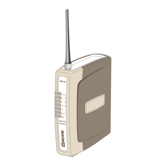
- Page 1 Reference Guide 6193-3201 RM-90 Wireless Ethernet Radio Modem www.westermo.com...
- Page 2 Thank you for your selection of the RM-90 Wireless Ethernet Modem. We trust it will give you many years of valuable service. 6193-3201...
- Page 3 ATTENTION! Incorrect termination of supply wires may cause internal damage and will void warranty. To ensure your RM-90 enjoys a long life, double check ALL your connections with the users manual before turning the power on. Caution! For continued protection against risk of fire, replace the internal module fuse only with the same type and rating.
-
Page 4: Fcc Notice
FCC Notice: This user’s manual is for the WESTERMO RM-90 radio telemetry module. This device complies with Part 15.247 of the FCC Rules. Operation is subject to the following two conditions: … This device may not cause harmful interference and …... -
Page 5: Important Notice
Like all industrial electronic products, WESTERMO products can fail in a variety of modes due to misuse, age, or malfunction. We recommend that users and designers design systems using design techniques intend- ed to prevent personal injury or damage during product operation, and provide failure tolerant systems to prevent personal injury or damage in the event of product failure. -
Page 6: Network Topology
100Mbit/sec. The module will transmit the Ethernet messages on the wireless band at up to 200 Kbit/sec. 1.1 Network Topology The RM-90 is an Ethernet device, and must be configured as part of an Ethernet network. Each RM-90 must be configured as: … an “Access Point” or a “Client”, and …... - Page 7 An Access Point could be used as a “Repeater” unit to connect two RM-90 Clients which do not have direct reliable radio paths. Bridge vs Router Each RM-90 is configured with an IP address for the Ethernet side, and another for the wireless side.
-
Page 8: Getting Started Quickly
… Set the RM-90 address settings as per section 3.4 … Save the configuration – the RM-90 is now ready to use. Before installing the RM-90, bench test the system. It is a lot easier to locate problems when the equipment is all together. -
Page 9: Antenna Installation
Chapter Two INSTALLATION 2.1 General The RM-90 module is suitable for DIN-rail mounting. Terminals will accept wires up to 12 gauge (2.5 sqmm) in size. All connections to the module must be SELV. Normal 110-240V mains supply should not be connected to any terminal of the RM-90 module. Refer to Section 2.3 Power Supply. - Page 10 Where it is not possible to achieve reliable communications between two RM-90 mod- ules, then a third RM-90 module may be used to receive the message and re-transmit it. This module is referred to as a repeater. This module may also have a host device con- nected to it.
- Page 11 Where antennas are mounted on elevated masts, the masts should be effectively earthed to avoid lightning surges. For high lightning risk areas, surge suppression devices between the module and the antenna are recommended. If the antenna is not already shielded from lightning strike by an adjacent earthed structure, a lightning rod may be installed above the antenna to provide shielding.
- Page 12 2.2.2 Yagi antennas. A Yagi antenna provides high gain in the forward direction, but lower gain in other direc- tions. This may be used to compensate for coaxial cable loss for installations with mar- ginal radio path. The Yagi gain also acts on the receiver, so adding Yagi antennas at both ends of a link pro- vides a double improvement.
-
Page 13: Power Supply
2.3 Power Supply The RM-90 module can be powered from a 10 – 30VDC power supply. The power supply should be rated at 1 Amp and be CSA Certified Class 2. The negative side of the supply should be connected to a good “ground” point for surge protection. The supply negative is connected to the unit case internally. - Page 14 Ring indicator – 2.4.2 RS-485 Serial Port The RS-485 port provides for communication between the RM-90 unit and its host device using a multi-drop cable. Up to 32 devices may be connected in each multi-drop network. As the RS-485 communication medium is shared, only one of the units on the RS-485 cable may send data at any one time.
- Page 15 100M LINK RS-485 RMINATION SETUP ETHERNET RS-232 (MDI X) (DCE) RS-485 POWER 6193-3201...
-
Page 16: Discrete (Digital) Input/Output
2.5 Discrete (Digital) Input/Output The RM-90 has one on-board discrete/digital I/O channel. This channel can act as either a discrete input or discrete output. It can be monitored, or set remotely, or alternatively used to output a communications alarm status. -
Page 17: Chapter Three Operation
Chapter Three OPERATION 3.1 Start-up “Access Point” Start-up An Access Point unit starts and immediately begins transmitting periodic messages called beacons. These beacon messages are messages contain information for Clients on how to establish a link with the Access Point. Any Client that hears the messages, which are not already linked to another Access Point unit, will respond and links will be established between the new Access Point and these Clients. - Page 18 The RM-90 will reset the Link if: … Excessive retries: When a RM-90 unit transmit a wireless message to another unit, the destination unit will transmit back an acknowledgment. If the source unit does not receive an acknowl- edgment, it will re-send the message – this is known as a “re-try”. Both Access Point and Client will drop the link if the number of retries for a single packet exceeds (7) times.
-
Page 19: Default Configuration
Ethernet address for the RM-90 is 192.168.0.1XX where XX are the last two digits of the serial number (check the label on the back of the module). The second method requires setting an IP address in the RM-90 such that it is accessible on your network without having to change your network settings. - Page 20 Switch Factory Default dip-switch on RM-90 to SETUP position. b) Connect the RS-232 port on the RM-90 to the RS-232 port on the PC using a “straight-through” serial cable. c) Open a terminal package (such as Hyperterminal) with 19200bps data rate, 8 data bit, 1 stop, no parity and no flow control.
-
Page 21: Quick Configuration
3.4 Quick Configuration The RM-90 has default configurations which will cover most applications. These param- eters can be manually changed however this is not necessary for the majority of applica- tions. - Page 22 The System Generator String is an alpha-numeric string of between 1 and 31 characters. Characters can be any ASCII alpha-numeric character (except the “null” character). The RM-90 uses this string as an input to pseudo-random algorithms to create the following parameters: …...
-
Page 23: Network Configuration
Used to select Access Point or Client mode. By default this is set to Client. Bridge Priority The priority of the RM-90, if configured as a bridge, in the Bridge Spanning Tree algorithm. By default this is set to the lowest priority at 255. -
Page 24: Ethernet Data
These are the keys used to encrypt radio data to protect data from unwanted eavesdroppers. These keys must be set the same for all RM-90 units in the same system. If encryption is not selected, the Key values can be ignored. -
Page 25: Normal Operation
The RM-90 has one routing rule which may be configured. This routing rule is the gate- way address. The RM-90 will direct all unknown IP network traffic to this gateway IP address. - Page 26 3.9 Radio Configuration Menu The RM-90 can be configured to different radio transmission rates. A reduction in rate increases the reliable range (transmission distance). An “automatic rate” function is pro- vided which automatically selects the highest data rate for reliable operation.
- Page 27 This is the difference (in dB) strength of transmissions. The Fade Margin value between the received radio signal is used by the RM-90 to determine when to and the receiver sensitivity (mini- change data rates. A larger Fade Margin means mum radio signal).
- Page 28 This selects the maximum number of bytes that will be transmitted in one message. If more than The maximum transmission unit this number of bytes is input into the RM-90, the (MTU) of data over the radio. module will transmit more than one message.
- Page 29 Contention Window Size This configurable parameter was introduced in firmware V1.18 This field sets the number of transmission slots available for usage by Clients. Each Client in the system has an individual time slot, to reduce radio communications clash. This field can be set to optimise throughput for particular applications.
- Page 30 Priority of (255) by default. The intention is reduce traffic that the RM-90 must handle, by placing it at the branch level in the network tree. As a branch, the RM-90 needs only pass traffic to devices that are its “leaves”.
- Page 31 Simply switch the dipswitch to SETUP and cycle power. The RM-90 will retain its configuration, however will load up at IP address 192.168.0.1XX, netmask 255.255.255.0 with the radio and filter disabled.
- Page 32 PPP server, Serial Gateway, and Modbus TCP to RTU server. 3.12.1 RS-232 PPP Server The RM-90 can be used as a PPP Server to connect the wireless Ethernet system to serial devices via the RS-232 or RS-485 serial ports.
- Page 33 IP addresses in the “LMHOSTS” file on your PC. When in SETUP mode, the RM-90 PPP server is enabled. This may also be used to config- ure the module. Settings whilst in SETUP mode are as follows: …...
- Page 34 PC. This virtual serial port can be configured to con- nect to a RM-90 serial port. Standard programs can then be used to access this serial port as if it were actually connected to the PC. Alternatively the program telnet may be used to connect to a serial port on the RM-90.
- Page 35 Modbus RTU Slave. The RM-90 makes this possible by internal- ly performing the necessary protocol conversion. The conversion is always performed by the RM-90 which is directly connected to the Modbus serial device (i.e. only this module needs to have Modbus TCP to RTU Server enabled).
- Page 36 The above example demonstrates how a Modbus/TCP Client (Master) can connect to one or more Modbus RTU (i.e serial) Slaves. In this example the RM-90 Access Point is configured with the “RS-232 Modbus/TCP to RTU Gateway” enabled. Once enabled, the gateway converts the Modbus/TCP queries received from the Master into Modbus RTU queries and forwards these over the RS-232 port to the Slave.
- Page 37 Module Information Webpage Fields This configuration page is primarily for information purposes. With the exception of the password, the information entered here is displayed on the root webpage of the RM-90. Password When changing the password on this screen, it will be sent unencrypted over any wired net- Configuration password.
- Page 38 Access Point Configuration Connect straight through Ethernet cable between PC and RM-90. … Ensure configuration PC and RM-90 are setup to communicate on the same network … Set dipswitch to SETUP mode. … Power up unit, and wait for LINK led to cease flashing.
- Page 39 Set dipswitch to SETUP c) Connect straight through serial cable to RM-90 and power up unit. d) When prompted, strike the Enter key to abort automatic boot e) Set IP address of RM-90 to 192.168.0.200 with command bip 192.168.0.200 f) Set netmask of RM-90 to 192.168.0.200 with command bnm 255.255.255.0...
- Page 40 Access Point Configuration … Connect straight through Ethernet cable between PC and RM-90. … Ensure configuration PC and RM-90 are setup to communicate on the same network … Set dipswitch to SETUP … Power up unit, and wait for LINK led to cease flashing.
- Page 41 … Connect straight through Ethernet cable between PC and RM-90. … Ensure configuration PC and RM-90 are setup to communicate on the same network … Set dipswitch to SETUP … Power up unit, and wait for LINK led to cease flashing.
- Page 42 Chapter Four DIAGNOSTICS 4.1 Diagnostics Chart LED Indicator Condition Meaning GREEN Normal Operation Supply voltage too low. Radio RX GREEN flash Radio receiving data Radio RX RED flash Weak radio signal Radio TX Flash Radio Transmitting Radio LINK On when a radio communications link is estab- lished Radio LINK Communications failure or radio link not estab-...
-
Page 43: Diagnostic Information Available
Boot Loader LED Indication during Startup Serial LINK ACTIVE Comment Orange Orange Orange Initial Power Up & bootload Initialisation Orange Orange Check Config & Print Sign-on message (If boot delay not zero) Orange Orange Orange Print Configuration Table to terminal (If boot delay not zero) Green Initialise Networking and Start Auto... -
Page 44: Testing Radio Paths
IP address for the RM-90 at first startup. This command would be written as Ping 192.168.123.123 then Enter to send the ping command. The pc will reply with an acknowledgement of your command if your RM-90 is correctly configured. - Page 45 RM-90 refer to Section 1.1 The RM-90 can only accept 1 Routing table. That is it can only accept one router per network of radios. On the Router radio network PC a routing rule needs to entered to allow access between Network A and Network B.
- Page 46 Network A Settings Client Bridge Settings IP Address 192.168.0.17 Gateway IP 192.168.2.51 Subnet Mask 255.255.255.0 Ethernet IP 192.168.2.50 Gateway IP 192.168.0.1 Subnet Mask 255.255.255.0 Wireless IP 192.168.2.50 Subnet Mask 255.255.255.0 Access Point Router Settings Network B Settings Gateway IP 192.168.0.1 IP Address 192.168.2.201 Ethernet IP 192.168.0.191 Subnet Mask 255.255.255.0...
-
Page 47: Specifications
Chapter Five SPECIFICATIONS General EMC specification FCC Part 15 EN 300 683 89/336/EEC AS 3548 Radio specification FCC Part 15.427 902 – 928MHz, 0.1 – 1W AS 4268.2 915 – 928MHz, 0.1 – 1W RFS29 NZ 920 – 928MHz, 0.1 – 1W Housing 35 x 150 x 135mm Plastic housing... - Page 48 General Expected line-of-sight USA / Canada 20+ miles @ 4W ERP range Australia / NZ 20+ km @ 1W ERP Range based on 19200 depending on local baud conditions Range may be extended 60+ miles can be achieved in using intermediate low RF noise environments modules as repeaters.
-
Page 49: Firmware Upgrade
9. Switch dip-switch on RM-90 to SETUP mode. 10. Click on Upgrade button in FlashUpdate program. 11. Click OK. 12. Power up RM-90, or cycle power to RM-90, within 30 seconds of completing the previous step. 13. Programming will commence. -
Page 50: Appendix B Glossary
Appendix B GLOSSARY Acknowledgment. Access point An access point is the connection that ties wireless communication devices into a network. Also known as a base station, the access point is usually connected to a wired network. Antenna Gain Antennae don’t increase the transmission power, but focus the signal more. - Page 51 CSMA/CD A method of managing traffic and reducing noise on an Ethernet network. A network device transmits data after detecting that a channel is available. However, if two devices transmit data simultaneously, the sending devices detect a collision and retransmit after a random time delay.
- Page 52 A multiport device used to connect PCs to a network via Ethernet cabling or via WiFi. Wired hubs can have numerous ports and can transmit data at speeds ranging from 10 Mbps to multigigabyte speeds per second. A hub transmits packets it receives to all the connected ports.
- Page 53 IP address A 32-bit number that identifies each sender or receiver of information that is sent across the Internet. An IP address has two parts: an identifier of a particular network on the Internet and an identifier of the particular device (which can be a server or a workstation) within that network.
- Page 54 Router A device that forwards data from one WLAN or wired local area network to another. Signal to Noise Ratio. The number of decibels difference between the signal strength and background noise. Transmit Power The power usually expressed in mW or db that the wireless device transmits at.
- Page 55 Server A computer that provides its resources to other computers and devices on a network. These include print servers, Internet servers and data servers. A server can also be combined with a hub or router. Site survey The process whereby a wireless network installer inspects a location prior to putting in a wireless network.
- Page 56 TCP/IP The underlying technology behind the Internet and communications between computers in a network. The first part, TCP, is the transport part, which matches the size of the messages on either end and guarantees that the correct message has been received. The IP part is the user’s computer address on a network.
- Page 60 E-mail : infos@westermo.fr E-mail: contact@ontimenet.com Westermo Data Communications Ltd Talisman Business Centre • Duncan Road Park Gate, Southampton • SO31 7GA Phone: +44(0)1489 580-585 • Fax.:+44(0)1489 580586 E-Mail: sales@westermo.co.uk Westermo Teleindustri AB have distributors in several countries, contact us for further information.
Need help?
Do you have a question about the RM-90 and is the answer not in the manual?
Questions and answers