Westermo ODW-720-F1 User Manual
Fibre optic modem
Hide thumbs
Also See for ODW-720-F1:
- User manual (19 pages) ,
- User manual (54 pages) ,
- User manual (18 pages)

Related Manuals for Westermo ODW-720-F1


Summary of Contents for Westermo ODW-720-F1
- Page 1 User Guide 6651-2221 ODW-720-F1 Fibre Optic Modem Industrial Converter RS-232 to Fibre Optic Link. Point to Point applications www.westermo.com...
-
Page 2: Legal Information
Under no circumstances shall Westermo be responsible for any loss of data or income or any special, incidental, and consequential or indirect damages howsoever caused. -
Page 3: Before Installation
Do not use or store the unit in dusty, dirty areas. Connectors as well as other mechanical parts may be damaged. If the unit is not working properly, contact the place of purchase, nearest Westermo distributor office, or Westermo Tech support. -
Page 4: Maintenance
ATEX** EN 60079-0 and EN 60079-15 * Applicable for ODW-720-F1 only ** Applicable for ODW-720-F1 Ex only FCC Part 15.105 This equipment has been tested and found to comply with the limits for a Class A digital device, pursuant to Part 15 of the FCC Rules. These limits are designed to provide... - Page 5 ATEX Information (Applicable for ODW-720-F1 EX only) General This unit is intended for use in Zone 2 hazardous location only. Marking II 3 G Ex nA IIC T4 Gc SPECIAL CONDITION WARNING – DO NOT SEPARATE WHEN ENERGIZED Indicate that this unit complies with relevant European standards that are harmonised with the 94/9/EC Directive (ATEX).
-
Page 6: Safety Control Drawing
Ratings Power (12 – 48) VDC; 300 mA –40ºC ≤ Ta ≤ +70ºC Ambient temperature Ingress protection (IP) IP21 Maximum surface temperatur 135ºC (temperature class T4) Safety Control Drawing Degree of protection IP 21 Ambient temperature –40°C to +70°C Minimum 25 mm above / below Installation spacing Minimum 10 mm left / right Direction relative this unit! -
Page 7: Special Condition For Safe Use
SPECIAL CONDITION FOR SAFE USE Ambient temperature: This unit is designed for use in extreme ambient temperature conditions as follows: –40 ºC ≤ Ta ≤ +70 ºC Installation in an apparatus cabinet: This unit requires installation in an Ex certified apparatus cabinet suitable for the area of use and providing a degree of protection of at least IP54. -
Page 8: Declaration Of Conformity
Declaration of Conformity Westermo Teleindustri AB Declaration of conformity The manufacturer Westermo Teleindustri AB SE-640 40 Stora Sundby, Sweden Herewith declares that the product(s) Type of product Model Art no Industrial fiberoptic repeaters/media ODW-700 series 3651-07xx converters ODW-700EX series 3651-37xx is in conformity with the following EC directive(s). -
Page 9: Type Tests And Environmental Conditions
7.5 mm, 5 – 8 Hz 2 g, 8 – 500 Hz Shock IEC 60068-2-27 Operating 15 g, 11 ms Packaging Enclosure, ODW-720-F1 UL 94 PC / ABS Flammability class V-1 Enclosure, Cabelec 6141 ODW-720-F1 EX Dimension W x H x D... -
Page 10: Functional Description
ODW-720-F1 is a fibre optic modem that converts between electrical RS-232 and a fibre optic link. ODW-720-F1 can also be used to convert from RS-232 to RS-485 by using one ODW- 720-F1 and one ODW-730-F1. Data rate up to 250 kbit/s ODW-720-F1 converts data using rates from 300 bit/s up to 250 kbit/s. -
Page 11: Interface Specifications
Interface specifications Power Rated voltage ODW-720-F1: 12 to 48 VDC and 24 VAC ODW-720-F1 Ex: 12 to 48 VDC Operating voltage ODW-720-F1: 10 to 60 VDC and 20 to 30 VAC ODW-720-F1 Ex: 10 to 60 VDC Rated current 300 mA @ 12 V... - Page 12 RS-232 Electrical specification EIA RS-232 Data rate 300 bit/s – 250 kbit/s Protocol Asynchronous or synchronous Data format 9 – 12 bits in asynchronous mode Any type in synchronous mode Data retiming Asynchronous mode only Transmission range 15 m Isolation to Status and Power port Connection 9-pin D-sub female (DCE)
- Page 13 Bi-di Bi-di Bi-di FX (Fibre) LC-40 LC-20 MM LC-2 Fibre connector LC Simplex LC Simplex LC Simplex Fibre type Singlemode Singlemode Multimode 9/125 µm 9/125 µm 62.5/125 and 50/125 µm Wavelength nm, connector 1 Tx 1310, rx 1550 Tx1310, rx 1550 Tx 1310, rx 1550 Wavelength nm, connector 2 Tx 1550, rx 1310...
-
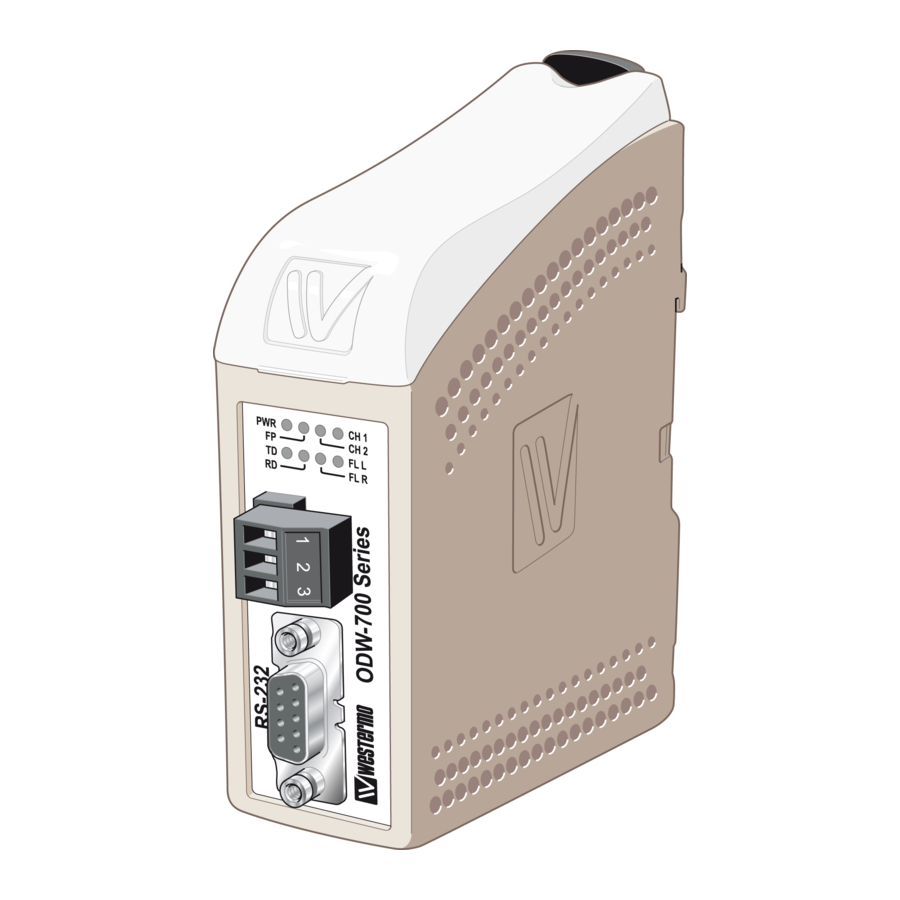
Page 14: Direction* Description
Location of Interface ports, LED’s and DIP-switches ODW-720-F1 DIP-switches accessible under lid (for details see page 16) LED Indicators (for details see page 15) Status screw terminal Position Description Product marking Contact with C when fibre optical links are in operation... -
Page 15: Led Indicators
A fibre link is out of operation at this unit. Flashing Hardware error or invalid configuration. * Only valid if used togheter with ODW-720-F1 units in a multidrop network. Note: During power up, all LED’s will turn on for about 1 second. 6651-2221... -
Page 16: Dip Switch Settings
(e.g. use of wrist strap) Note: Disconnect power before DIP-switch settings. The ODW-720-F1 DIP-switches are pre-set from the factory, so that the unit can be used for point-to-point applications, togheter with an additional ODW-720-F1, straight out of the box, without the need for any type of user configuration. - Page 17 After a few seconds the fibre link should be in operation, indicated by an active CH1 LED. … Connect the serial cables from PLC master and slave to respective ODW-720-F1. … Frames from PLC master that are correctly received the ODW-720-F1 should be indicated by flashing TD LED.
-
Page 18: Status Port
The ODW-720-F1 power supply is galvanically isolated from all other interfaces. Optical fibre interfaces ODW-720-F1 uses Small Form Factor Pluggable (SFP) transceivers. This means that a wide range of different fibre transceivers and connectors can be used (see page 12–13). - Page 19 Mounting This unit should be mounted on 35 mm DIN-rail, which is horizontally mounted inside an apparatus cabinet, or similar. Snap on mounting, see figure. Cooling 10 mm * (0.4 inches) This unit uses convection cooling. To avoid obstructing the air- 25 mm flow around the unit, use the following spacing rules.
- Page 20 9 Chemin de Chilly 91160 CHAMPLAN Phone:+886 2 8911 1710 Tél : +33 1 69 10 21 00 • Fax : +33 1 69 10 21 01 E-mail: info@westermo.com E-mail : infos@westermo.fr Westermo Teleindustri AB have distributors in several countries, contact us for further information.
Need help?
Do you have a question about the ODW-720-F1 and is the answer not in the manual?
Questions and answers