Table of Contents
Advertisement
User Guide
6650-2212
ODW-612
Fibre Optic Modem
Industrial Converter
PROFIBUS DP to
Fibre Optic Link.
Repeater, line and redundant ring
www.westermo.com
AUDIN - 8, avenue de la malle - 51370 Saint Brice Courcelles - Tel : 03.26.04.20.21 - Fax : 03.26.04.28.20 - Web : http: www.audin.fr - Email : info@audin.fr
Advertisement
Table of Contents

Related Manuals for Westermo ODW-600 Series


Summary of Contents for Westermo ODW-600 Series
- Page 1 PROFIBUS DP to Fibre Optic Link. Repeater, line and redundant ring www.westermo.com AUDIN - 8, avenue de la malle - 51370 Saint Brice Courcelles - Tel : 03.26.04.20.21 - Fax : 03.26.04.28.20 - Web : http: www.audin.fr - Email : info@audin.fr...
-
Page 2: Legal Information
Under no circumstances shall Westermo be responsible for any loss of data or income or any special, incidental, and consequential or indirect damages howsoever caused. -
Page 3: Before Installation
Do not use or store the unit in dusty, dirty areas. Connectors as well as other mechanical parts may be damaged. If the unit is not working properly, contact the place of purchase, nearest Westermo distributor office, or Westermo Tech support. -
Page 4: Agency Approvals And Standards Compliance
Note. Fibre Optic Handling Fibre optic equipment requires careful handling as the fibre components are very sensitive to dust and dirt. If the fibre is disconnected from the modem, the protective plug on the transmitter/receiver must be replaced. The protective plug must be kept on during transportation. -
Page 5: Declaration Of Conformity
Declaration of Conformity Westermo Teleindustri AB Declaration of conformity The manufacturer Westermo Teleindustri AB SE-640 40 Stora Sundby, Sweden Herewith declares that the product(s) Type of product Model Art no Industrial fiberoptic repeaters/media ODW-600 Series 3650-0xxx converters is in conformity with the following EC directive(s). -
Page 6: Type Tests And Environmental Conditions
Type tests and environmental conditions Electromagnetic Compatibility Phenomena Test Description Level EN 61000-4-2 Enclosure contact ± 6 kV Enclosure air ± 8 kV RF field AM modulated IEC 61000-4-3 Enclosure 10 V/m 80% AM (1 kHz), 80 – 800 MHz 20 V/m 80% AM (1 kHz), 800 –... - Page 7 Description Introduction The ODW-612 is a fibre optic modem for Redundant ring and multidrop applications. It acts as a repeater between the two fibre optic links, and as a converter between fibre optical links and the electrical PROFIBUS DP. The maximum distance of the fibre link depends on selected transceiver and fibre type. Distance up to 80 km (50 miles).
-
Page 8: Functional Description
Functional description Switches LED’s POWER PROFIBUS DP Internal Electronics RxD/TxD - P RxD/TxD - N SHIELD STATUS CH 1 Fibre transceiver CH 2 Fibre transceiver Over Voltage Protection OCP Over Current Protection Converter PROFIBUS DP – optical fibre ODW-612 is a fibre optic modem that converts between electrical PROFIBUS DP and a fibre optical link. - Page 9 Redundant ring via fibre optical network Under normal operation the PROFIBUS DP data is sent over ring A. Should a fault be detected on the fibre ring then the PROFIBUS DP data will be carried on rings A and B. Ring A Ring A Ring A...
- Page 10 Failure Corrective action Indications Fibre interruption ring A, TX Switch to ring B On: FL R Fibre interruption ring A, RX Switch to ring B On: FL L Fibre interruption ring A, RX & TX Switch to ring B On FL L Fibre interruption ring B, TX –...
- Page 11 Optical fibre link functionality and status indication At power on, all LED's will be active during an initiation sequence followed by an auto- matic initiation of the optical fibre links. The alarm will be set until the fibre optical links are in operation and ready to transfer PROFIBUS DP data.
- Page 12 System delay in an optical network Data exchange between a PROFIBUS DP master and slave via ODW-612 fibre optic link, will be delayed due to the length of the optical fibre and the signal processing within the ODW-612. The signal processing delay is dependent on the data rate, and the fibre delay is dependent on the total length of the optical fibre.
- Page 13 Multidrop, one data exchange. • The data exchange between PROFIBUS DP master and slave via ODW-612 fibre optic link will run from the ODW-600 units connected to PROFIBUS DP master to the slave and the same way back to the master. The system delay is calculated by summing the following: 1.
-
Page 14: Interface Specifications
Interface specifications Power Rated voltage 12 to 48 VDC 24 VAC Operating voltage 10 to 60 VDC 20 to 30 VAC Rated current 400 mA @ 12 VDC 200 mA @ 24 VDC 100 mA @ 48 VDC Rated frequency Inrush current I 0.2 A Startup current*... -
Page 15: Optical Power Budget
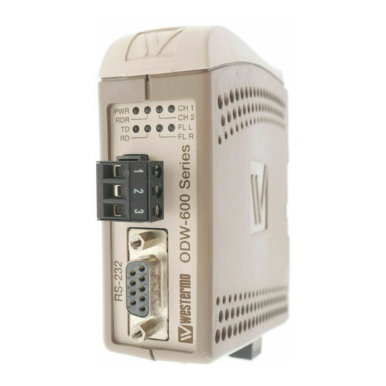
FX (Fibre) SM-LC80 SM-LC40 SM-LC15 MM-LC2 Fibre connector LC duplex LC duplex LC duplex LC duplex Fibre type Singlemode Singlemode Singlemode Multimode 9/125 μm 9/125 μm 9/125 μm 62.5/125 and 50/125 μm Wavelength 1550 nm 1310 nm 1310 nm 1310 nm Transmitter –5/0 dBm –5/0 dBm... - Page 16 Connections DIP-switches accessible under lid (for details see page 18) LED Indicators (for details see next page) Status screw terminal 3-position Direction Description No. 1 Contact with C when link is in operation FX(Fibre) (for details No. 2 Common see page 15) No.
-
Page 17: Led Indicators
LED Indicators Status Description In service (power). Power Flashing Fault condition. Out of service. PROFIBUS DP in operation. Bus active Received data frame with detected data rate on the electrical PROFIBUS DP or optical fibre port. Data frame with detected data rate has not been received, or received frames have been interrupted during a time, or a number of consecutive... -
Page 18: Dip Switch Settings
DIP-switch settings Before setting DIP-switches: Prevent damage to internal electronics from electrostatic discharges (ESD) by discharging your body to a grounding point (e.g. use of wrist strap). S1 DIP-switch Set status port at local fibre link error 1 2 3 4 5 6 7 8 S2 DIP-switch Multidrop, end unit application. - Page 19 Faulty frame before data rate is seen as unidentified Description DIP-switch DIP-switch 1 faulty frame before data rate is seen as unidentified. S1: No extended retry limit. 1 2 3 4 5 6 7 8 1 2 3 4 5 6 7 8 2 faulty frame before data rate is seen as unidentified.
- Page 20 Mounting This unit should be mounted on 35 mm DIN-rail, which is horizontally mounted inside an apparatus cabinet, or similar. Snap on mounting, see figure. Cooling 10 mm * (0.4 inches) This unit uses convection cooling. To avoid obstructing the air- 25 mm flow around the unit, use the following spacing rules.
-
Page 21: Start-Up Guide
Start up guide Redundant ring application Follow the steps below to get the unit up and running in a simple application. Ring A Ring A Ring A Ring A CH 2 CH 1 CH 2 CH 1 CH 2 CH 1 CH 2 CH 1 TX RX... - Page 22 Multidrop application Follow the steps below to get the unit up and running in a simple application. CH 2 CH 1 CH 2 CH 1 CH 2 CH 1 CH 2 CH 1 PROFIBUS DP PROFIBUS DP PROFIBUS DP PROFIBUS DP Slave Master Slave...
- Page 23 Hints If the fibre distance is long it may be necessary to adjust the bus parameter Slot time, the monitoring time (t bit ) of the sender of frame for acknowledgement of recipient and the TSDR Station Delay of Responders, at configuration of the PROFIBUS DP master. If the time between transferred PROFIBUS DP frames is long, it may be necessary to allow a longer time of interruption in receiving frames, using DIP-switches.
- Page 24 E-Mail: info@westermo.de Westermo Teleindustri AB have distributors in several countries, contact us for further information. AUDIN - 8, avenue de la malle - 51370 Saint Brice Courcelles - Tel : 03.26.04.20.21 - Fax : 03.26.04.28.20 - Web : http: www.audin.fr - Email : info@audin.fr...
Need help?
Do you have a question about the ODW-600 Series and is the answer not in the manual?
Questions and answers