Advertisement
Quick Links
Advertisement

Subscribe to Our Youtube Channel
Related Manuals for Videofied XL 3.1


Summary of Contents for Videofied XL 3.1
- Page 1 Videofied XL Programming Module 3:1...
- Page 2 MODULE 3.1 : VIDEOFIED XL SYSTEM PROGRAMMING Learning Outcomes : 1. Knowledge of Videofied XL Panel and associated peripherals 2. Ability to program a Videofied XL System 3. Ability to add and delete Videofied devices 4. Ability to perform radio (RF) device range tests 5.
- Page 3 1. GOLDEN RULES - XL 1. Devices in Area 1 are ALWAYS subject to Entry and Exit delay. 2. If a Keypad or Badge Reader is entered into an Area, then all the devices in this Area are also subject to Entry/Exit delays. 3.
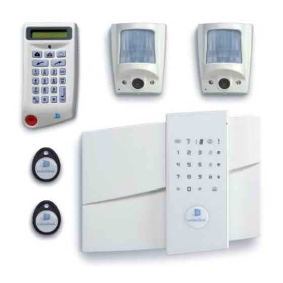
- Page 4 2. What we need to begin? • Videofied XL Panel • 8 x Energizer ‘D’ cell alkaline batteries • Wireless keypad (CMA701) • Indoor MotionViewer (DCV701) • Outdoor MotionViewer (DCV751) • Wireless Universal Device – Reed (CT701) • Remote Control (RC701) •...
- Page 5 Videofied XL Panel...
- Page 6 3. Programming XL Panel Refer to the XL programming manual Page 3 ii. Remove the XL panel from the box iii. Insert SIM card into the panel as shown:...
- Page 7 3. Programming XL Panel IV. Assemble the XL panel Affix rear panel on the wall and clip in front of panel...
- Page 8 3. Programming XL Panel CONNECT POWER LEAD Connect power cable and insert batteries. Keypad should light up and flash (a beep should be heard).
- Page 9 3. Programming XL Panel DEFAULT THE PANEL Hold down the PROGRAM BUTTON on the panel for 10 seconds until the keypad beeps again and lights up all the keys of the panel keypad.
- Page 10 3. Programming XL Panel RECORD KEYPAD Press and release instantly the PROGRAM BUTTON of the panel again to switch to keypad registration mode.
-
Page 11: Record The Keypad
3. Programming XL Panel RECORD THE KEYPAD (Ref. Keypad installation data sheet) • Insert the 3 Lithium LS14500 batteries in the keypad. • Do not mount the keypad. • Simultaneously press the [CLR] and [ESC NO] buttons on the keypad, until the keypad’s LED flashes, then release. - Page 12 3. Programming XL Panel BEGIN PROGRAMMING - RADIO RANGE TEST KEYPAD DISPLAY KEYPAD 1 PRESS RECORDED <LANGUAGE> ENGLISH PRESS RADIO RANGE Perform a radio range test between the XL PRESS TEST? panel and the keypad. Must not be less than 5/9 radio strength. RADIO RANGE Allow 30 seconds for signal strength to stabilize.
- Page 13 3. Programming XL Panel ENTERING INSTALLER CODE KEYPAD DISPLAY There is no default installer code, it is what ENTER THE is entered at this stage. WAIT INSTALLER CODE Installers code will take up 1 of the 20 user 4 to 6 DIGITS code/proximity badge slots WAIT THEN YES...
-
Page 14: Adjusting Date & Time
3. Programming XL Panel ADJUSTING DATE & TIME KEYPAD DISPLAY ADJUSTING TIME AND DATE DATE (YEAR) : Repeat for MONTH, DAY, TIME and MINUTES 00/ /... - Page 15 3. Programming XL Panel MONITORING STATION SETTINGS KEYPAD DISPLAY CONNECTED TO PRESS MONITORING STATION? ACCOUNT NUMBER: Enter the client account number provided by monitoring station then PERIODIC TEST Hourly Periodic tests will significantly shorten the battery life PERIODIC TEST: 24 HOURS...
- Page 16 3. Programming XL Panel MONITORING STATION SETTINGS.. KEYPAD DISPLAY TEST HOUR: 00:0 CODE/STATE MODIFICATION? By default events that are transmitted to the monitoring station are: DEVICE (Intrusion), PANIC, TAMPERS, PERIODIC TEST, LOW PANEL BATTERIES, LOW DEVICE BATTERIES, SUPERVISION FAULT.
-
Page 17: Area Configuration
3. Programming XL Panel XIII AREA CONFIGURATION KEYPAD DISPLAY AREA CONFIGURATION AREA NAME 1 : Enter the name of Area 1 and then Repeat this for Areas 2, 3 and 4. Areas are the logical areas that devices will reside within. For example Area 1: Entry Foyer (delayed) Area 2: Front Offices Area 3: Warehouse... -
Page 18: Entry - Exit Delay
3. Programming XL Panel ENTRY – EXIT DELAY KEYPAD DISPLAY Exit Delays can be EXIT DELAY: either 45 sec, 1min or 45 sec 2min ENTRY DELAY: Entry Delays can be 15 Sec either 15 sec, 30 sec, 45 sec, 1min or 2min... - Page 19 3. Programming XL Panel GPRS PARAMETERS - CONFIGURATION • APN (Access Point Name) information entered KEYPAD DISPLAY depends upon your SIM service provider. GPRS • APN information must be entered in lower case PRESS PARAMETERS? • A username and password is used for corporate network APN: Service...
-
Page 20: Gprs Parameters
GPRS PARAMETERS IP Address or Domain Name of CMS main server and backup server APN (Access Point Name) USERNAME and PASSWORD is provided by your service provider These values should never be changed without Technical Support Approval IP Address or Domain Name of CMS remote maintenance SMTP server if panel has to send email e.g. - Page 21 3. Programming XL Panel GPRS Parameters - CONFIGURATION KEYPAD DISPLAY If using APN telstra.wap USERNAME To enter a Username (public network) no username Press and enter or password is required. Leave Username and PASSWORD the username and Password blank then arrow right and If using telstra.corp or repeat for password another private network, then...
- Page 22 To enter a IP1 Press the IP or domain name. and enter the IP Domain Name 1 followed by Videofied systems report to either the IP or the Domain. NOTE: When the : Both should NOT be entered appears then digits can be entered in the field.
- Page 23 3. Programming XL Panel GPRS Parameters - CONFIGURATION KEYPAD DISPLAY Right arrow to PORT 1. PORT 1 By Default this should be 888. Right arrow past this to IP 2. Check with monitoring station to confirm this is the case, 9 times out of 10 it is.
- Page 24 KEYPAD DISPLAY Right arrow to IP2 or IP 2 OR Domain 2 is the IP2 ADDRESS Domain 2. monitoring stations backup Videofied IP or Domain server. To enter a IP2 Press and enter the IP Domain NAME 2 followed by...
- Page 25 3. Programming XL Panel GPRS Parameters - CONFIGURATION KEYPAD DISPLAY Right arrow to PORT 2. PORT 2 By Default this should be 888. Right arrow past this to TMT IP. Check with monitoring station to confirm this is the case, 9 times out of 10 it is.
- Page 26 IP1 or DOMAIN 1. So the same NOTE: TMT is used by the can be entered here. Videofied panel to initiate a Enter only TMT IP or TMT communication so maintenance DOMAIN. Leave the other can be performed. Pressing...
- Page 27 3. Programming XL Panel GPRS Parameters - CONFIGURATION KEYPAD DISPLAY Right arrow to PORT TMT. PORT TMT By Default this should be 888. Press To exit GPRS parameters Check with monitoring station to confirm this is the case, 9 times out of 10 it is.
- Page 28 3. Programming XL Panel If an error appears. GPRS LEVEL 1. Repeat test. CHECK: GPRS Level will appear. KEYPAD DISPLAY 2. SIM is active for GPRS Press GPRS LEVEL? 3. Security PIN code on sim has been disabled A GPRS signal level test will TEST IN PROGRESS 4.
- Page 29 3. Programming XL Panel Refer to your device XVII ADDING VIDEOFIED DEVICES installation sheets. KEYPAD DISPLAY Take your Videofied device PRESS PROGRAM Press sync button (MotionViewer, reed BUTTON OF DEVICE of device switch) and open up. Device Check in Insert the batteries.
- Page 30 3. Programming XL Panel Radio range test XVII ADDING VIDEOFIED DEVICES Take your Videofied device KEYPAD DISPLAY and with the keypad, walk RADIO RANGE Press to the area the device will TEST? be positioned. Test that the radio range Press...
- Page 31 3. Programming XL Panel AREA Allocation XVII ADDING VIDEOFIED DEVICES Remembering that Area 1 KEYPAD DISPLAY Right arrow to has a keypad enrolled in it, AREA ALLOCATION select AREA 2, 3 making this area AREA: 1 or 4 then ENTRY/EXIT Delayed, we...
-
Page 32: Finishing Installation
3. Programming XL Panel XIIX FINISHING INSTALLATION KEYPAD DISPLAY Once all the devices have OPERATION Press been added, a check of the COMPLETED? system will automatically take place. Radio device SYSTEM CHECK IN issues, tampers etc will be PROGRESS displayed I there are errors. INSTALLATION SUCESSFUL! - Page 33 4. Adding User Code - XL Panel AFTER entering the User ENTERING USER CODE Code, you can then allocate a USER CODE NAME. KEYPAD DISPLAY At DISARMED State DISARMED LVL:4 Various levels of ACCESS to BADGES ACCESS CODES (1,2,3,4) can then be modified BADGES under ‘BADGES ACCESS Then press...
-
Page 34: Deleting Devices
5. Deleting Devices – XL Panel AFTER entering the User DELETING DEVICES Code, you can then allocate a USER CODE NAME. KEYPAD DISPLAY At DISARMED State DISARMED LVL:4 Various levels of ACCESS to LVL: (1,2,3,4) can then be modified ACCESS LEVEL under ‘BADGES ACCESS Then press CODES’/‘BADGE/CODE... - Page 35 5. Deleting Devices – XL Panel DELETING DEVICES DELETING DEVICES - KEYPAD It is important to delete devices before physically removing KEYPAD DISPLAY them from the Videofied panel. to AREAS AND DEVICES AREAS AND Then press Failing to do so will create a DEVICES radio supervision fault.
- Page 36 6. GPRS Level Test – XL Panel GPRS LEVEL TEST – AFTER PROGAMMING XXII GPRS Level should not be less KEYPAD DISPLAY than 3/5 and NEVER less than DISARMED LVL:4 to MAINTENANCE then press MAINTENANCE GPRS LEVEL? to GPRS LEVEL? then press TEST IN PROGRESS The GPRS level will commence/...
- Page 37 7. Device Locating – RF Testing DEVICE LOCATION – RADIO RANGE TEST XXIII RF – Radio range test of KEYPAD DISPLAY devices should not read less DISARMED LVL:4 to MAINTENANCE then than 7/9. Press MAINTENANCE Leave device in position for 30 seconds to allow radio to DEVICE LOCATING to DEVICE LOCATING then...
-
Page 38: Adding Additional Devices
8. Adding Additional Devices - XL Panel XXIV ADDING ADDITIONAL DEVICES The Videofied XL Panel can KEYPAD DISPLAY accommodate up to 19 to AREAS AND DEVICES AREAS AND Then press additional devices including DEVICES Motionviewers, reed switches, keyfobs, siren strobes. - Page 39 9. Re- Enrolling Wireless Keypad - XL Panel RE – ENROLLING THE WIRELESS KEYPAD KEYPAD DISPLAY On the front of the XL Panel PRESS and HOLD the for 3 seconds You have successfully entered the programming mode when the display flashes. Type in ‘000000’...
- Page 40 10. DCV701 Motionviewer XXVI Enrolling a DCV701 Motionviewer KEYPAD DISPLAY to AREAS AND DEVICES AREAS AND Then press DEVICES DEVICES DEVICES then PRESS ADD A NEW ADD A NEW DEVICE Press DEVICE Insert the batteries and close. PRESS PROGRAM Press the program using a BUTTON OF DEVICE paperclip –...
- Page 41 11. DCV701 Motionviewer XXVI Enrolling a DCV701 Motionviewer KEYPAD DISPLAY PRESS PROGRAM Press sync button BUTTON OF DEVICE of device Device Check in Progress CAMERA 1 Press RECORDED Name of Camera Change the name of the camera and area...
- Page 42 11. DCV701 Motionviewer Radio range test XXVI Enrolling a DCV701 Motionviewer Take your Videofied KEYPAD DISPLAY Motionviewer device, and RADIO RANGE Press with the keypad, walk to TEST? the area the device will be positioned. Press to end test Test that the radio range test is no less than 7/9 on the keypad display.
- Page 43 11. DCV 701 Indoor Motionviewer XXVII Placement of DCV 701 Motionviewer •Mount Motionviewer at height of 2.1 – 2.3 mtrs •Do not mount infront of air vent •Field of view of detector is 90 degrees •Camera field of view is 88 degrees •Detection range of up to 12 mtrs •IR capability up to 7 mtrs •Camera resolution 320 x 240...
- Page 44 12. DCV751 Outdoor Motionviewer XXVIII. Outdoor Motionviewer Motion Sensor Bi-Directional Radio Transceiver to Panel Night Vision Digital Camera • Self-powered • No AC connection • Up to 2 Year Life Infrared Illuminators...
- Page 45 12. DCV751 Motionviewer XXVIII Enrolling a DCV751 Motionviewer KEYPAD DISPLAY to AREAS AND DEVICES AREAS AND Then press DEVICES DEVICES DEVICES then PRESS ADD A NEW ADD A NEW DEVICE Press DEVICE Insert the batteries PRESS PROGRAM Press the program – sync button BUTTON OF DEVICE of device as per installation sheet of device...
- Page 46 12. DCV751 Outdoor Motionviewer XXVIII Enrolling a DCV751 Motionviewer KEYPAD DISPLAY If device sync has been received the display will indicate device check in progress Device Check in Progress CAMERA 1 Press RECORDED Name of Camera Change the name of the camera and area...
- Page 47 12. DCV751 Outdoor Motionviewer Radio range test XXVIII Enrolling a DCV751 Motionviewer Take your Videofied KEYPAD DISPLAY Motionviewer device, and RADIO RANGE Press with the keypad, walk to TEST? the area the device will be positioned. Press to end test...
- Page 48 12. DCV 751 Outdoor Motionviewer XXVIII Placement of DCV 751 Motionviewer •Mount Motionviewer at height of 2 – 3 mtrs •Angle Motionviewer mount down to cut off field of view to max 10 mtrs •Motionviewer should be used to protect assets and things not areas. Doorways, gates, vehicles, fuel tanks etc (refer next image) •Remember this is intruder video verification not surveillance •Field of view of detector is 90 degrees...
- Page 49 12. DCV 751 Outdoor Motionviewer XXIX Placement of DCV 751 Motionviewer Angle down to cutoff field of view to 10 mtrs maximum...
- Page 50 13. RC701 Keyfob Enrolling a RC701 Keyfob KEYPAD DISPLAY to AREAS AND DEVICES AREAS AND Then press DEVICES DEVICES DEVICES then PRESS ADD A NEW ADD A NEW DEVICE Press DEVICE...
- Page 51 13. RC 701 Keyfob XXVI Enrolling a RC701 Keyfob KEYPAD DISPLAY PRESS PROGRAM Press program buttons: BUTTON OF DEVICE Hold down ON & OFF together for 5 – 10 seconds Device Check in and release. If not successful Progress repeat process KEYFOB Press RECORDED...
- Page 52 14. RC701 Wireless Universal Transmitter - Reed XXXI Enrolling a RC701 Wireless Universal Transmitter - Reed KEYPAD DISPLAY to AREAS AND DEVICES Then press AREAS AND DEVICES DEVICES then PRESS DEVICES ADD A NEW DEVICE Press ADD A NEW DEVICE Insert the batteries Using a paper clip Press the program –...
- Page 53 14. RC701 Wireless Universal Transmitter - Reed XXXI Enrolling a RC701 Wireless Universal Transmitter - Reed KEYPAD DISPLAY If device sync has been received the display will indicate device check in progress Device Check in Progress DETECTOR Press RECORDED Name of DETECTOR Change the name of the camera and area...
- Page 54 14. RC701 Wireless Universal Transmitter - Reed XXXI Enrolling a RC701 Wireless Universal Radio range test Transmitter - Reed Take your Videofied KEYPAD DISPLAY Motionviewer device, and RADIO RANGE Press with the keypad, walk to TEST? the area the device will be positioned.
- Page 55 14. RC701 Wireless Universal Transmitter - Reed XXXII Wiring external trigger to a RC701 Wireless Universal Transmitter - Reed...
- Page 56 5. The device will transmit the tamper state, serial number, manufacture date and firmware version 6. All Videofied devices, with the exception of the Keyfob are polled by the control panel every 8 minutes. This polling confirms communication and general device status.
-
Page 57: Device Specifications
5. DEVICE SPECIFICATIONS CONTROL PANEL VIDEOFIED : XL GPRS The Control Panel Model XL GPRS is a VIDEOFIED® wireless, battery operated control panel. The control panel is designed for security applications where video verification is needed or desired. S2View® - Spread Spectrum, VIDEOFIED®, Interactive AES Encrypted Wireless technology provides optimum signal integrity and security. - Page 58 CONTROL PANEL VIDEOFIED : VISIO GPRS The Control Panel Model VISIO is a VIDEOFIED® wireless, battery operated security system control panel. The control panel is designed for security applications where video verification is needed or desired. S2View® - Spread Spectrum, VIDEOFIED®, Interactive AES Encrypted Wireless technology provides optimum signal integrity and security.
- Page 59 When the existing panel is armed this also arms the XTENDER. S2View® - Spread Spectrum, VIDEOFIED®, Interactive AES Encrypted Wireless technology provides optimum signal integrity and security. Compatibility - works with all VIDEOFIED® wireless devices.
- Page 60 The Keypad Model CMA is a battery operated, wireless alphanumeric keypad designed for configuring/programming and operating VIDEOFIED® security systems S2View® - Spread Spectrum, VIDEOFIED®, Interactive AES Encrypted Wireless technology provides optimum signal integrity and security Mobility - program the system from anywhere on site.
- Page 61 MOTIONVIEWER CAMERA : DCV The MotionViewer DCV is a battery operated, wireless indoor motion- activated video camera designed for use in VIDEOFIED® security systems. Motion-activated cameras are intended for applications where video verification of intrusion alarms is necessary or desired.
- Page 62 OUTDOOR MOTIONVIEWER CAMERA :DCV The Outdoor MotionViewerTM Camera DCV is a battery operated, wireless outdoor motion activated camera designed for use in Videofied® security systems. S2View® - Spread Spectrum, Videofied®, Interactive AES Encrypted Wireless technology provides optimum signal integrity and security.
- Page 63 The Outdoor Proximity Reader Model BR is a battery operated, wireless Proximity Reader designed for arming and disarming operation of VIDEOFIED® security systems. S2View® - Spread Spectrum, VIDEOFIED®, Interactive AES Encrypted Wireless technology provides optimum signal integrity and security. Mobility - Use outdoors or indoors with a fully weather proof housing with standing temperatures from -20°...
- Page 64 DOOR CONTACT : CT The Door Contact Models CT are battery operated, wireless door contacts designed for use in VIDEOFIED® security systems. Door contacts are intended for use in detecting the opening and closing of doors, windows, or cabinet doors/drawers.
- Page 65 KEYFOB : RC The Keyfob Model RC is a battery operated, wireless remote control designed for basic operation of VIDEOFIED® security systems. S2View® - Spread Spectrum, VIDEOFIED®, Interactive AES Encrypted Wireless technology provides optimum signal integrity and security. Operate system from within or just outside premises.
- Page 66 OUTDOOR SIREN STROBE : SE The Outdoor Siren/Strobe Model SE is a battery operated, wireless combination unit designed for use in Videofied® security systems. S2View® - Spread Spectrum, Videofied®, Interactive AES Encrypted Wireless technology provides optimum signal integrity and security.
Need help?
Do you have a question about the XL 3.1 and is the answer not in the manual?
Questions and answers