Advertisement
Quick Links
Product Summary
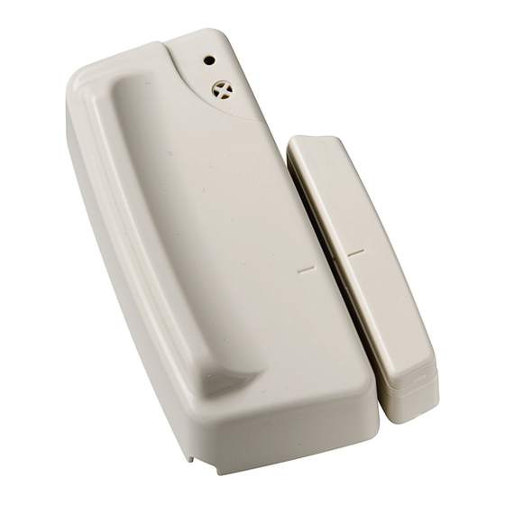
The Door Contact Models CT600/CT201/CT700 (white) CT610/
CT211/CT710 (brown), are wireless, universal door contacts de-
signed for use in RSI VIDEO TECHNOLOGIES ™ security systems. The
contact includes the following features:
>
Lithium battery for long life
>
External input for normally closed (NC) intrusion devices
>
Dual tamper function provides detection for both wall
and cover tamper.
>
Transmits check-in/status signal every 8 minutes
Programming/RF Testing
The following provides summarized steps for device
programming and testing. For complete details, refer
to the control panel installation manual.
1
Loosen bottom screw, separate base
from detector and install battery.
2
Re-attach base to secure tamper switch.
3
Put control panel into programming/
configuration mode.
4
Using a programmed alphanumeric
keypad, proceed through menus
until the display shows ADD A
NEW DEVICE.
5
Press Yes. The display shows
PRESS PROGRAM BUTTON OF DEVICE.
6
Press and release program button on detector using a
paper clip end. The detector LED flashes. Wait for keypad
display to show DETECTOR (1 - 24) RECORDED.
7
Press Yes. The display shows RADIO RANGE TEST?
Press Yes again. The detector LED starts flashing and
keypad display shows TEST IN PROGRESS.
8
Take detector to its intended mounting location and
make sure LED flashes continuously, indicating good
communication with control panel.
9
Press Yes to end radio range test, then press Esc/No.
Door Contact Models
I N S T A L L A T I O N I N S T R U C T I O N S
Made by RSI VIDEO TECHNOLOGIES
Installation Guidelines
For easier installation, programming and RF testing
should be done to check for good communication between
the control panel and all system devices before mounting
system devices. Install the detector and other system
devices in the following order:
>
Programming/RF Testing—program detector and
all other devices into the control panel and test RF
communication from each intended device location
to the control panel.
>
Mounting—mount detector at the tested location.
10
The display shows AREA
ASSIGNMENT AREA: 1. Press
either arrow button repeatedly
until desired AREA number
Screw
appears, then press Yes.
1 1
The display shows PROTECT AN
EXTERNAL ACCESS? Press Yes or
Esc/No, whichever is appropriate
for this device.
12
The display shows NAME + LOCATION.
Enter appropriate device name/location (up to
16 characters), then press Yes. The display shows
the device number and name for your verification.
13
Press Yes. The display shows FUNCTIONAL DEVICE
TEST? Press Yes again and verify detector operation.
For example, move magnet next to detector to make
LED go out, then move magnet away from detector
to make LED turn on indicating detection.
14
Press Yes to end detection verification.
15
The display shows ADD A NEW DEVICE?
Repeat steps 1 - 14 for remaining detectors.
16
When finished, exit from configuration mode.
CT600/CT610/CT201/CT211/CT700CT710
1008-c February 2008
Program Button
www.videofied.com
LED
Advertisement

Related Manuals for Videofied CT211


Summary of Contents for Videofied CT211
- Page 1 The Door Contact Models CT600/CT201/CT700 (white) CT610/ For easier installation, programming and RF testing CT211/CT710 (brown), are wireless, universal door contacts de- should be done to check for good communication between signed for use in RSI VIDEO TECHNOLOGIES ™ security systems. The...
- Page 2 Phone 877-06-5800 Fax +33 (0)3 90 20 66 36 Fax 651-762-4693 www.videofied.com © 2007 RSI VIDEO TECHNOLOGIES™ Videofied ® is a Registered Trademark of RSI VIDEO TECHNOLOGIES™. View is a registered trademark of RSI VIDEO TECHNOLOGIES™. Specifications subject to change without notice.
Need help?
Do you have a question about the CT211 and is the answer not in the manual?
Questions and answers