Table of Contents
Advertisement
Quick Links
Advertisement
Table of Contents

Related Manuals for Jung 2103 REG ES


Summary of Contents for Jung 2103 REG ES
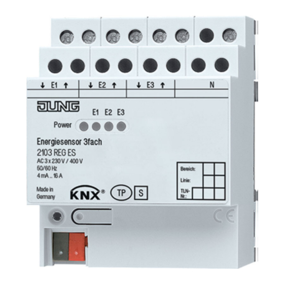
- Page 1 Energy detector 3-gang Ref.-no. 2103 REG ES ALBRECHT JUNG GMBH & CO. KG Volmestraße 1 58579 Schalksmühle Telephone: +49 (0)2355 806-0 Telefax: +49 (0)2355 806-204 kundencenter@jung.de https://www.jung.de/en/ Service Center Kupferstr. 17-19 Date of the documentation: 06.2020 44532 Lünen Germany...
-
Page 2: Table Of Contents
Specification ...................... 11 5.2. Overview ......................12 5.2.1. Measured values ..................12 5.2.2. Energy counter ..................... 13 5.2.3. Rate counters ....................15 5.3. Object table ....................... 17 5.4. Parameters ....................... 24 Ref. no. 2103 REG ES Page 2 of 44... -
Page 3: Information On The Product
Intended use Energy counter for alternating or three-phase current 110/400 V AC / 50 Hz + 60 Hz, for recording and visualising consumption values in KNX. Not approved for billing purposes. Ref. no. 2103 REG ES Page 3 of 44... -
Page 4: Structure Of The Device
KNX supply KNX Medium TP 1 Commissioning mode S-Mode KNX rated voltage DC 21 ... 32 V SELV Current consumption by KNX bus: ≤ 18.9 mA Connection type KNX Connection terminal Ref. no. 2103 REG ES Page 4 of 44... - Page 5 ≤ 0.8 W / phase Power consumption from mains: < 1 W The stated values only apply if the currents an voltage are sine and undistorted and the output factor is 1. Ref. no. 2103 REG ES Page 5 of 44...
-
Page 6: Safety Instructions
Ensure a minimum distance of at least 4 mm between bus and mains voltage wires. Do not open the device or operate it outside of its technical specifications. These instructions are an integral part of the product, and must remain with the end customer. Ref. no. 2103 REG ES Page 6 of 44... -
Page 7: Mounting And Electrical Connection
On removal, the neutral conductor must be disconnected from the device last. NOTE: A load must always be inserted between the output and the neutral conductor (>< symbol). The output and neutral conductor may not be connected without a load. Ref. no. 2103 REG ES Page 7 of 44... -
Page 8: Operation With External Current Transformers
The device only supports external current transformers with a primary current of 75 A and a 5 A secondary current. We recommend using the same transformer type for each of the three inputs of the energy detector 2103 REG ES. Current transformers of type PACT MCR-V1-21-44-75-5A-1 (PHOENIX CONTACT Reference number 2277611) are recommended with the accessories of the support rail adapter PACT MCR-RA (PHOENIX CONTACT Reference number 2277598). - Page 9 2103 REG ES. The poles of the secondary sides of the current transformers are to be connected using the inputs E1, E2 and E3 of the energy detector 2103 REG ES. The cable cross-section must be 2.5 mm Ref.
-
Page 10: Operational Instructions
E1, E2, E3, before reconnecting the primary circuit. The connection of the current transformers to the inputs E1, E2 and E3 of the energy detector 2103 REG ES prevents such surge voltages. The connection of the secondary sides of the current transformers with the input voltage means that the current transformers and their connections have a 230 V voltage potential. -
Page 11: Application
Application Application The operation of the energy detector 2103 REG ES with external current convertors is supported from Version 0.2 of the device software onwards. You can determine the version level using the "Device information" ETS function (Fig. 4). ETS: Device information If the device software is an older version, then an update to Version 0.2 or... -
Page 12: Overview
The measured values are calculated in intervals of one second. The transmission process is distributed over a time period of one second in order to reduce the bus load. Ref. no. 2103 REG ES Page 12 of 44... -
Page 13: Energy Counter
In addition, each type of counter possesses special characteristics. These are shown as a comparison in the following table: Ref. no. 2103 REG ES Page 13 of 44... - Page 14 When Trigger 2 is received, the counter level of the intermediate counter is transmitted on the bus. In addition, it is possible to configure whether receipt of Trigger 2 also causes a stop. Ref. no. 2103 REG ES Page 14 of 44...
-
Page 15: Rate Counters
We would like to point out that the three-phase current counter values and cost counter values shown in Fig. 7 can also be negative, if the basic active three-phase current power is negative. Ref. no. 2103 REG ES Page 15 of 44... - Page 16 According to According to download / power failure three-phase current three-phase current three-phase current / restart counter, Rate 1 counter, Rate 2 counter, Rate 3 Table 2: Properties of the cost counter Ref. no. 2103 REG ES Page 16 of 44...
-
Page 17: Object Table
Active power and Reactive power. Object Name Object function Type Flag 6, 12, 18 Chn MV Voltage (rms.) 2 bytes 9.020 CR-T- Description: The effective value of the channel voltage in mV. Ref. no. 2103 REG ES Page 17 of 44... - Page 18 4 bytes 14.056 CR-T- 23, 27 Description: The reactive power of the channel in VAr. Object Name Object function Type Flag Frequency 4 bytes 14.033 CR-T- Description: The mains frequency in Hz. Ref. no. 2103 REG ES Page 18 of 44...
- Page 19 Description: If the limit value for the counter level of the ¼-hour counter of the channel is over or undershot, a monitoring telegram can be transmitted, whose value is "1" on overshooting or "0" on undershooting. Ref. no. 2103 REG ES Page 19 of 44...
- Page 20 Name Object function Type Flag 40, 63, Chn EC Rate 2 Counter reading 4 bytes 13.010 CR-T- 86, 109 Description: The counter level of the channel for Rate 2 in Wh. Ref. no. 2103 REG ES Page 20 of 44...
- Page 21 Reset counter reading 1 bit 1.017 C-W-- 93, 116 Description: The counter level of the channel for Rate 3 is reset on receiving this object. The value of the object is irrelevant here. Ref. no. 2103 REG ES Page 21 of 44...
- Page 22 4 bytes 13.xxx CR-T- Description: The object contains the currently incurred costs for Rate 2. These are calculated from the counter level of the three-phase current energy counter for Rate 2. Ref. no. 2103 REG ES Page 22 of 44...
- Page 23 ETS is overwritten. However, the price of the Rate will be set back to the price configured by the ETS on the next ETS download. The transmitted integer value is interpreted in 0.1 ct/kWh. Ref. no. 2103 REG ES Page 23 of 44...
-
Page 24: Parameters
Transformer external current transformers. measurement 75 A Appr. comm. object ‚Request measured Here, it is possible to enable the object for requesting the measured values. values‘ Ref. no. 2103 REG ES Page 24 of 44... - Page 25 Send frequency on change (0.1 Hz) 0...650 The measured frequency can be transmitted on changes. Setting of the frequency change, at which the measured frequency is transmitted, or switch-off of this function with the value 0. Ref. no. 2103 REG ES Page 25 of 44...
- Page 26 / bus voltage failure or permanently overwrites the value configured with the ETS. Limit value (h) 0..4240 Specification of the limit value for the effective power measured on Channel 1. Ref. no. 2103 REG ES Page 26 of 44...
- Page 27 The effective power measured on Channel 2 can be transmitted on changes. Setting of the effective power change, at which the measured effective power is transmitted, or switch-off of this function with the value 0. Ref. no. 2103 REG ES Page 27 of 44...
- Page 28 The voltage measured on Channel 3 can be transmitted on changes. Setting of the voltage change, at which the measured voltage is transmitted, or switch-off of this function with the value Ref. no. 2103 REG ES Page 28 of 44...
- Page 29 The reactive power measured on Channel 3 can be transmitted on changes. Setting of the reactive power change, at which the measured effective power is transmitted, or switch-off of this function with the value 0. Ref. no. 2103 REG ES Page 29 of 44...
- Page 30 The reactive three-phase current power can be transmitted on changes. Setting of the reactive power change, at which the measured effective power is transmitted, or switch-off of this function with the value 0. Ref. no. 2103 REG ES Page 30 of 44...
- Page 31 Counter after ETS download No reaction Here, it is possible to set whether the Reset counter levels of Channel 1 remain unchanged after an ETS download or are reset to 0. Ref. no. 2103 REG ES Page 31 of 44...
- Page 32 Here, it is possible to specify whether the current counter of Channel 1 for parameters Via trigger objects Rate 2 is to be activated using Rate parameters (i.e. time or Rate object) or via trigger objects. Ref. no. 2103 REG ES Page 32 of 44...
- Page 33 Here, it is possible to set whether a Telegram on limit value (¼-hour telegram is transmitted when a limit counter value) value of the ¼-hour counter value of Channel 2 is over or undershot. Ref. no. 2103 REG ES Page 33 of 44...
- Page 34 2 can be transmitted on a change by a configured value: Counter level Counter level, Rate 1 Counter level, Rate 2 Counter level, Rate 3 Setting of the change at which the counter levels are to be transmitted. Ref. no. 2103 REG ES Page 34 of 44...
- Page 35 Channel 2 for Rate 1. Approve object Here, it is possible to enable the object 'Reset current counter rate 1' for resetting the current counter level of Channel 2 for Rate 1. Ref. no. 2103 REG ES Page 35 of 44...
- Page 36 Counter after ETS download No reaction Here, it is possible to set whether the Reset counter levels of Channel 3 remain unchanged after an ETS download or are reset to 0. Ref. no. 2103 REG ES Page 36 of 44...
- Page 37 Here, it is possible to specify whether the current counter of Channel 3 for parameters Via trigger objects Rate 2 is to be activated using Rate parameters (i.e. time or Rate object) or via trigger objects. Ref. no. 2103 REG ES Page 37 of 44...
- Page 38 Here, it is possible to set whether a Telegram on limit value (¼-hour telegram is transmitted when a limit counter value) value of the ¼-hour counter value of the three-phase current variables is over or undershot. Ref. no. 2103 REG ES Page 38 of 44...
- Page 39 1/4-hour counter value cyclic sending The ¼-hour counter level of the three- phase current variables can be excluded from the cyclical transmission configured above, in order to reduce the bus load. Ref. no. 2103 REG ES Page 39 of 44...
- Page 40 Via trigger objects current variables for Rate 3 is to be activated using Rate parameters (i.e. time or Rate object) or via trigger objects. Ref. no. 2103 REG ES Page 40 of 44...
- Page 41 The set Rate Rate 2 applies until a different Rate is selected Rate 3 after receipt of the current time or As above another Rate is specified via the Rate object. Ref. no. 2103 REG ES Page 41 of 44...
- Page 42 Setting of the day at which Rate 2 starts. End (hour) 0...23 Setting of the end hour of Rate 2. End (minute) 0...59 Setting of the end minute of Rate 2. Ref. no. 2103 REG ES Page 42 of 44...
- Page 43 Setting of the end hour of Rate 3. End (minute) 0...59 Setting of the end minute of Rate 3. End (weekday) Every day Setting of the day at which Rate 3 ends. Ref. no. 2103 REG ES Page 43 of 44...
- Page 44 Application Albrecht Jung GmbH & Co. KG Volmestrasse 1 58579 Schalksmühle www.jung.de sign is a free trade sign addressed Subject to change without notice. 09/2020 exclusively to the authorities and does not include any warranty of any properties. Ref. no. 2103 REG ES...
Need help?
Do you have a question about the 2103 REG ES and is the answer not in the manual?
Questions and answers