Advertisement
Quick Links
Radio Management
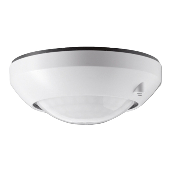
Radio presence detector
Radio presence detector
Art. No. : FPM360WW
Radio presence detector
Art. No. : FPM360AL
Operating instructions
1 Safety instructions
Electrical equipment may only be installed and fitted by electrically skilled persons.
Serious injuries, fire or property damage possible. Please read and follow manual fully.
Risk of explosion! Do not throw batteries into fire.
Risk of explosion! Do not recharge batteries.
The radio communication takes place via a non-exclusively available transmission path,
and is therefore not suitable for safety-related applications, such as emergency stop and
emergency call.
Do not press on the sensor window. Device can be damaged.
These instructions are an integral part of the product, and must remain with the end
customer.
2 Device components
(1) Sensor window with LED under it
(2) Decor ring
(3) Base plate
(4) Button
(5) Sensitivity adjuster
(6) Run-on time adjuster
(7) Brightness setpoint adjuster
82536633
J0082536633
Figure 1
1/14
16.08.2016
Advertisement

Related Manuals for Jung FPM360WW


Summary of Contents for Jung FPM360WW
- Page 1 Radio Management Radio presence detector Radio presence detector Art. No. : FPM360WW Radio presence detector Art. No. : FPM360AL Operating instructions 1 Safety instructions Electrical equipment may only be installed and fitted by electrically skilled persons. Serious injuries, fire or property damage possible. Please read and follow manual fully.
- Page 2 Radio Management Radio presence detector 3 Function System information By statute, the transmitting power, the reception characteristics and the antenna cannot be changed. The range of a radio system from the transmitter to the receiver depends on various circumstances. The range of the system can be optimised by selecting the optimal installation location, taking into account the structural circumstances.
- Page 3 Radio Management Radio presence detector 4 Operation 4.1 Light control with dimmer actuator When the brightness drops below a setpoint and when a motion is detected the taught dimmer actuator switches the taught dimmer actuator on for the duration of the set run-on time. Every additional motion detection starts the run-on time again.
- Page 4 Radio Management Radio presence detector Figure 3 Using the radio hand transmitter: Select channel group C and then press channel button 8 (/\ or \/) for longer than 1 second (figure 3). For confirmation of the setpoint change the LED on the dimmer actuator lights up for approx.
- Page 5 Radio Management Radio presence detector 4.2 Light control with switch actuator When the brightness drops below a setpoint and when a motion is detected the taught dimmer actuator switches the taught switch actuator on for the duration of the set run-on time. Every additional motion detection starts the run-on time again.
- Page 6 Radio Management Radio presence detector i In the radio manual transmitter comfort the master dimming button is located under the 5 light scene buttons. The master dimming button of the hand-held transmitter affects all of the actuators that are participating in the light scene that was called up last. i With the radio wall transmitter the channel buttons 4+ and 4- have the master dimming functionality, if at least one of the other buttons is set to light scene operation.
- Page 7 Radio Management Radio presence detector At installation heights greater than 2.5 m the detection area becomes larger, while at the same time the detection density and sensitivity are reduced. i The push-on cover can be used to limit the detection area, e.g. in order to mask out interference sources.
- Page 8 Radio Management Radio presence detector Figure 7 Turn the presence detector clockwise by approx. 45° to detach it from the base plate (figure 7). Remove old batteries. Figure 8 i Once the batteries are inserted the device transmits teaching telegrams for approx. 30 seconds.
- Page 9 Radio Management Radio presence detector 5.2 Commissioning Teaching the presence detector in the radio detector The presence detector may be taught in only one receiver for light control. The teaching procedure only results in an assignment in the receiver. When a presence detector is taught-in the sensitivity of the receiver is reduced to approx. 5 m. The distance between the receiver and the presence detector being taught should therefore be between 0.5 m and 5 m.
- Page 10 Radio Management Radio presence detector Figure 10: Adjuster Pull decor ring (2) off of presence detector (figure 10). The sens adjuster (5) can be used to set the sensitivity of the sensor between maximum and minimum sensitivity. i At minimum sensitivity the presence detector does not trigger. The time adjuster (6) can be used to set the run-on time between approx.
- Page 11 Radio Management Radio presence detector Figure 11 Presence detector must be taught in the receiver. To activate the light control test mode, press the button (4) for at least 1 second (figure 11). The light control test mode is activated for about 5 minutes. During this time the LED (1) behind the sensor window first flashes 10 times quickly, then periodically every 5 seconds.
- Page 12 Radio Management Radio presence detector Limiting the detection area Figure 12: Push-on cover The push-on cover can be used to limit the detection area, e.g. in order to mask out interference sources. Cover size Detection area on the floor Complete cover Ø...
-
Page 13: Technical Data
Radio Management Radio presence detector Figure 13: Master – slave i Note the sequence: first teach the master presence detector, then the slave presence detector. Set the desired brightness setpoint on the master presence detector. This value applies for the entire system. Teach the master presence detector (see Teaching the presence detector in the radio receiver). -
Page 14: Troubleshooting
Change batteries (see Fitting chapter). 6.3 Conformity Albrecht Jung GmbH & Co. KG hereby declares that the radio system type Art. No. FPM360WW / FPM360AL corresponds to the directive 2014/53/EU. You can find the full article number on the device. The complete text of the EU Declaration of Conformity is available under the Internet address: www.jung.de/ce...
Need help?
Do you have a question about the FPM360WW and is the answer not in the manual?
Questions and answers