
Related Manuals for Car Solutions QVL-RCD-D4-MAIN-V1


Summary of Contents for Car Solutions QVL-RCD-D4-MAIN-V1
- Page 1 LAST UPDATED : 2011.08.24 Video Interface for RANGE ROVER cars with dual view LCD screen Installation + User Manual car-solutions.com support@car-solutions.com...
-
Page 2: Table Of Contents
Contents 1. Before installation 1.1 Main specification 1.2 Features 1.3 System diagram 1.4 Components 1.5 Exterior 2. SETUP 2.1 DIP switch 2.2 Remote control 2.3 OSD (on screen display) 2.4 FACTORY mode 2.5 Rear view parking guide line 2.6 Original button 3. -
Page 3: Main Specification
1.1 Main Specification 1. Input Spec. (MULTI VIDEO INTERFACE) -. 3 x A/V Input (External video source). -. 1 x CVBS(REAR CAMERA) Input. (Rear camera source) -. 1 x Analog RGB Input (Navigation System output) -. 1 x LCD Input (Car system Input) -. -
Page 4: Features
1.2 Features - Improved display quality - Working on NTSC, PAL - External Touch screen available by NAVI-SEL - AV1-SEL, REAR-SEL are added (For Rear-CAM Power) - Rear CAM detection by CAN - Possible to adjust displayed RGB, AV sources in Factory Mode - Possible to display OSD with no connection of AV sources car-solutions.com support@car-solutions.com... -
Page 5: System Diagram
1.3 System Diagram Remote Control Switch for source toggle OEM NAVI Button Navigation Input (Analog RGB) A/V1 DISPLAY A/V2 Car Installation OEM LCD VIDEO MUX VIDEO A/V3 CIRCUIT CVBS HEADREST (Rear MONITOR Camera) POWER CIRCUIT Car Screen Input SEL-OUT (Car Main Board) Power Input DIP S/W (+8VDC~+18VDC) -
Page 6: Components
1.4 Components TOUCH cable * 1ea (HTOUCH0005) BY-PASS cable * 2ea (HTOUCH0003) AV cable * 1ea (HAVCAB0002) RGB cable * 1ea (HNAVIC0002) TOUCH BOARD * 1ea FPC cable * 1ea (QCPASS0053) (SMTASY0080) IR cable * 1ea (HIRCAB0002) SEL cable * 1ea (HSELCA0001) MODE cable * 1ea (HARETC0001) -
Page 7: Exterior
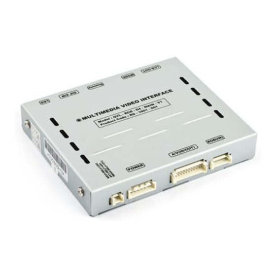
1.5 Exterior ⑨ ⑧ ⑦ ⑥ ⑤ Dimension Horizontal length 155mm Vertical length 91mm Height 20mm ① SEL-OUT ② POWER ③ AV(IN/OUT) ④ RGB(IN) ⑤ LDC-OUT ⑥ MODE ⑦ REMOTE ⑧ DIP S/W ① ② ③ ④ ⑨ LED car-solutions.com support@car-solutions.com... -
Page 8: Dip Switch
2.1 DIP switch ※DIP S/W Use Example #PIN FUNCTION DIP S/W Selection ON : Skipping RGB Mode RGB INPUT MUTE -. Use Input Mode : MAIN + A/V 3 OFF : RGB Display -. Rear Camera : When to be installed ON : Skipping A/V 1 on CVBS 4 A/V 1 MUTE... -
Page 9: Remote Control
2.2 Remote controller Function POWER & PIP Not for use MENU OSD implementation Making a selection ▲ Move upward ▼ Move downward Move leftward, press 5 seconds long-Factory ◀ mode implementation Move rightward ▶ * FACTORY MODE (Interface setting) : Operated with pressing ▲ -> ▼ -> ▲ ->MENU buttons on the remote control in sequence. car-solutions.com support@car-solutions.com... -
Page 10: Osd (On Screen Display)
2.3 OSD (on screen display) OSD menu: Press ”MENU” button on the remote control. Analog RGB MODE Analog RGB MODE Analog RGB MODE Video MODE Video MODE Video MODE IMAGE UTIL - LANGUAGE : To change the language BRIGHTNESS FACTORY RESET : To reset all displaying on navigation, DVD, CMMB OSD CONTRAST the values about navigation, DVD... -
Page 11: Factory Mode
2.4 Factory mode Factory mode: Operated with pressing ▲ -> ▼ -> ▲ ->MENU buttons on the remote control in sequence. IMAGE H_POSITION : Horizontal movement of the OSD window V_POSITION : Vertical movement of the OSD window PARK PARK ENABLE : Setup of rear view parking guide line PARK SETUP : Control over position of rear view parking guide line. -
Page 12: Rear View Parking Guide Line
Rear view parking guide line Factory mode: Operated with pressing ▲ -> ▼ -> ▲ ->MENU buttons on the remote control in sequence. ① Register the value needed on the “PARK ENABLE” as “ON” in the PARK section as shown left. ②... -
Page 13: Original Button
2.6 Original button MODE button (on the steering wheel) Long press the button : MODE Change Press the button shortly : Change to Main display ※ CAN Wiring! Connect the Brown+Green wire of CAN cable offered to Yellow+Green wire of the car, the Green wire of CAN cable offered to Yellow wire of the car as shown left. -
Page 14: Installation Diagram
3.1 Installation diagram ※ The power of interface should be connected with an power of an original monitor Original FPC cable DIP S/W Remote MODE LCD-OUT LAND ROVER Offered FPC cable Monitor VIDEO INTERFACE SEL(12V POWER A/V(IN/OUT) RGB(IN) Sub board NAVI-SEL AV1-SEL REAR-SEL... -
Page 15: Cautions On Installation
Cautions on installation Ignition key should be taken off before starting installation, interface power connection must be the last step in installation. Power cable should be separated when connecting interface. Should be no any electronic devices or magnetic pole around installation place. ... -
Page 16: Installation
3.3 Installation Original FPC Offered FPC ① ③ ② 1. Take apart the indicated Original touch cable and FPC cable from monitor as shown left. (For easier installation, disconnect the FPC② for a while) . Connect the offered FPC cable to the indicated Original FPC Original connector as shown right. -
Page 17: Connecting Can Cable
Connecting CAN cable Offered FPC CAN High CAN Low LVDS cable Touch cable GROUND cable Touch board Original touch out cable 4. Connect the Brown+Green wire of CAN cable offered to Yellow+Green wire of the 3. Connect the Sub-board and Touch car, the Green wire of CAN cable offered to board. -
Page 18: Troubleshooting
Troubleshooting Q. I can not switch A/V sources. A. Check IR or Ground cable connection. Check LED lamps in the interface, if it is not on, check power cable. Q. All I got on the screen is black. A. Check second LED lamp of the interface is on, if not, check A/V sources connected are working well. (Second lamp indicates AV sources connected works well.) Check interface connection has been done well.
Need help?
Do you have a question about the QVL-RCD-D4-MAIN-V1 and is the answer not in the manual?
Questions and answers