Table of Contents

Related Manuals for Car Solutions PIP-RGB-HE-STD-V5


Summary of Contents for Car Solutions PIP-RGB-HE-STD-V5
-
Page 1: User Guide
m odel : PI P-RG B-H E-STD -V5 / pr oduct code : PI P-RG -0810-861 m odel : PI P-RG B-H E-STD -V5 / pr oduct code : PI P-RG -0810-861 Video Interface for Merecedes-Benz W211 User Guide support@car-solutions.com www.car-solutions.com... - Page 2 1.1 Features -. POP(Picture On Picture) Function (Only available on navigation mode) -. Auto detection for NTSC & PAL&SECOM signals. -. Parking Guide Line function added -. “Sync On Green” supported (Auto detection) -. Able to change modes via mode switch -.
-
Page 3: Main Specification
1.2 Main Specification 1. Input Spec. (MULTI VIDEO INTERFACE) -. 3 x AV Input (External video source). -. 1 x CVBS (REAR CAMERA) Input (Rear camera source) -. 1 x Analog RGB Input (Car commander original monitor output) -. 1 x Analog RGB Input (Navigation System output)-OPTION 2. - Page 4 1. 3 Syst em D i agr am Sw i t ch f or sour ce t oggl e & REAR SENSE Rem ot e C ont r ol Navi gat i on I nput ( Anal og RG B) D I SPLAY I nst al l at i on M C U...
- Page 5 1.4 Components MODE cable * 1ea IR cable (3P) * 1ea (HARETC0001) GROUND cable (14P) * 1ea (HIRCAB0001) (HGROUN0002) Sub-board * 1ea (QCPASS0063) FFC cable (30P) * 1ea (FFCABL0003) RGB cable * 1ea AV cable * 1ea (HNAVIC0002) POWER cable (10P) * 1ea REMOTE CONTROL * 1ea support@car-solutions.com (HAVCAB0002)
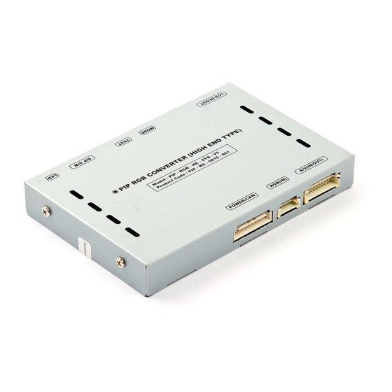
- Page 6 1.4 Exterior TEST(IR) MODE LCD IN/OUT DIP S/W Dimension Horizontal length 150mm Vertical length 95mm Height 21mm Power/CAN RGB(IN) AV (IN/OUT) support@car-solutions.com www.car-solutions.com...
-
Page 7: Wiring Diagram
1.5 Wiring diagram * Power cable FILTER & FUSE BOX REAR-C SAFE-N.C CAN(H)-N.C CAN(L)-N.C NAVI Sel AV1-Sel AV2-Sel AV3-Sel support@car-solutions.com www.car-solutions.com... -
Page 8: Dip Switch
2.1 DIP switch ON : DOWN, OFF : UP DIP S/W Use Example -. Use Input Mode : AV1, Navigation (RGB), Main -. Rear Camera : When to be installed on CVBS 4 ▷ DIP S/W : 1 OFF ▷... -
Page 9: Remote Controller
2.2 Remote controller Dimension : 85 * 40 * 8 (mm) *FACTORY MODE (Interface setting) : Operated with pressing ▲ -> ▼ -> ▲ ->MENU buttons of the remote in sequence. (Example : PIP implementation) support@car-solutions.com www.car-solutions.com... - Page 10 2.3 OSD (On Screen Display) Analog RGB Analog RGB Analog RGB Video Video Video IMAGE UTIL - BRIGHTNESS -LANGUAGE : To change the language - FACTORY RESET : To reset all the - CONTRAST displaying on navigation, DVD, CMMB values about navigation, DVD screen - SATURATION OSD menu (select 1 among English or to factory default.
-
Page 11: Factory Mode
2.3 OSD (On Screen Display) · Factory Mode - Operated with pressing ▲ -> ▼ -> ▲ ->MENU buttons of the remote in sequence. PARK UTIL - BUTTON : Car Model Setting for using Navi button - PARK ENABLE - H-POSITION (Refer to the next page for details) - V-POSITION - FACTORY RESET : Initializing... - Page 12 2.3 OSD (On Screen Display) This setting needed with wire soldering, if want to use Navi button for switching AV sources. (Refer to the next page for further details.) support@car-solutions.com www.car-solutions.com...
-
Page 13: Parking Guide Line
2.4 Parking guide line * Factory Default : DISPLAY - DISABLE ① When the car gear is in reverse, Enter to ① the Factory mode by ▲ → ▼ → ▲ →MENU button of remote control. Then, the left image will be displayed on the screen. - Page 14 2.4 Parking guide line ③ Can move the line with H-Position ③ on the factory mode. ④ Can move the line with V-Position ④ on the factory mode. support@car-solutions.com www.car-solutions.com...
-
Page 15: Cautions On Installation
Cautions on installation Ignition key should be taken off before starting installation, interface power connection must be the last step in installation. Power cable should be separated when connecting interface. Should be no any electronic devices or magnetic pole around installation place. ... -
Page 16: Installation Diagram
Installation diagram Please make sure that the installation should be carefully conducted to avoid MONITOR • If want to use Navi button, Solder from the damage of a monitor by gray wire of offered LCD cable to appointed point inside Head Unit. ESD(Electrostatic discharge) and - Applicable models : Cayenne misalignment while connecting the... - Page 17 Soldering Point Solder the gray wire on Ground cable which is connecting sub board with main board to the Head Unit as shown above. *Soldering point: 5th Pin from right *Original button : NAVI support@car-solutions.com www.car-solutions.com...
-
Page 18: Troubleshooting
Troubleshooting Q. I can not switch A/V sources. A. Check IR or Ground cable connection. Check LED lamps in the interface, if it is not on, check power cable. Q. All I got on the screen is black. A. Check second LED lamp of the interface is on, if not, check A/V sources connected are working well. (Second lamp indicates AV sources connected works well.) Check interface connection has been done well.
Need help?
Do you have a question about the PIP-RGB-HE-STD-V5 and is the answer not in the manual?
Questions and answers