Advertisement
Quick Links
Advertisement

Related Manuals for Car Solutions RGB-LE-V3


Summary of Contents for Car Solutions RGB-LE-V3
- Page 1 CONVERTER USER MANUAL support@car-solutions.com...
- Page 2 INDEX -. Pre-Caution -. Main Specification -. System Composition Map -. Out-Line Dimension -. MODULE EXTERNAL -. Connector Pin Assignment -. DIP SW Operation Process . DIP SW Operation Process -. Remote Control Guide -. Products composition - FAQ -. FAQ support@car-solutions.com...
- Page 3 -Pre-Caution - You must keep the car key taken off from the car while you work this and finally, connect power of the interface. - When to connect the interface cable, you must keep the power cable taken off. - You must work this at the environment without any static electricity or damages. - All of process on this installation should be done by professionals.
- Page 4 -Main Specification 1. Input Spec. (MULTI VIDEO INTERFACE) -. 2 x CVBS Input (External video source). -. 1 x CVBS (REAR CAMERA) Input (Rear camera source) - 1 x Analog RGB Input (Car commander original monitor output) -. 1 x Analog RGB Input (Car commander original monitor output) -.
- Page 5 -System Composition Map Remote ControlSwitch for source toggle & REAR SENSE NAVIGATION Input (Analog RGB) CAR Installation CVBS1 DISPLAY OEM LCD CVBS2 VIDEO CVBS CIRCUIT (Rear camera) VIDEO MUX Car Screen Input POWER CVBS OUT (CAR MAIN BOARD) HEADREST CIRCUIT MONITOR Power Input Dip S/W...
- Page 6 -Out-Line Dimension Out Line Dimension 129mm * 75mm * 21mm 129mm 75mm 21mm ※ This can change under manufacturer's circumstance support@car-solutions.com...
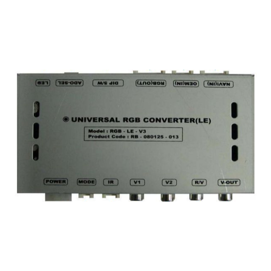
- Page 7 -Module External AUDIO-SEL DIP S/W RGB(OUT) OEM(IN) NAVI(IN) V-Out POWER MODE ※ This can change under manufacturer's circumstance support@car-solutions.com...
- Page 8 -Module External NAVI(IN) OEM(IN) RGB(OUT) DIP S/W ADO-SEL POWER POWER MODE MODE V OUT V-OUT ※ This can change under manufacturer's circumstance support@car-solutions.com...
- Page 9 -Connector Pin Assignment *NAVI-IN Connect *RGB-OUT Connect *RGB-OEM Connect ① ② ③ ④ ⑤ ⑥ ⑦ ①②③④⑤⑥⑦⑧⑨⑩ ①②③④⑤⑥⑦⑧⑨⑩ ① ② ③ ④ ⑤ ① ② ③ ④ ⑤ ① R DATA ① B Data : Blue ① R Data : Red ②...
- Page 10 -Connector Pin Assignment *Power Connect ⑤ ⑥ ⑥ ④ ① ③ ② ① ① GND ② I -Drive ③ F MTX ④ N.C ⑤ ACC ⑤ ⑥ R EAR ※ This can change under manufacturer's circumstance support@car-solutions.com...
- Page 11 -Connector Pin Assignment * Power cable FILTER & FUSE BOX Orange I - DRV Black Gray 990mm Orange Gray Gray LAMP - RV Black 990mm support@car-solutions.com...
- Page 12 -DIP SW Operation Process DIP SW Operation Process ※ ON : DOWN, OFF : UP ※DIP S/W Use Example #PIN FUNCTION DIP S/W Selection [W211] ON : Skipping RGB Mode -. Use Input Mode : CVBS1, Navigation (RGB), Main RGB INPUT MUTE -.
- Page 13 -Remote Control Guide Remote Control Guide Power : Mode is changed on only headrest monitor by this button, when front monitor shows Navigation or Rearview camera, Main. Source : When to change mode, you can change mode by this button. Navi : To change mode to Navigation directly AV1 : To change mode to A/V source you connected to A/V1 directly AV2 : To change mode to A/V source you connected to A/V2 directly...
- Page 14 -Products composition Products composition Power cable : 1 Audio Select Cable: 1 Mode cable : 1 RGB NAVI : 1 IR Cable : 1 RGB(Out) cable : 1 Remote Control : 1 t l 1 RGB OEM 1 RGB OEM : 1 support@car-solutions.com...
- Page 15 Installation Structure MONITOR B G R C D C W C R G B R G B c D B G R RG B RG B c D Offered ADO-SEL DIP S/W RGB(OUT) OEM(IN) NAVI(IN) Original RGB CONVERTER(LE) Control Box Control Box POWER MODE...
- Page 16 -FAQ 1. When can not change mode. -. Check if the IR Cable (remote control) is connected or not. -. Check if LED is turned on or not. If it is not turned on, Check if power cable is connected or not. 2.
Need help?
Do you have a question about the RGB-LE-V3 and is the answer not in the manual?
Questions and answers