
Subscribe to Our Youtube Channel
Related Manuals for Promise Technology UltraTrack RM4000


Summary of Contents for Promise Technology UltraTrack RM4000
- Page 1 LTRA ERIES RM4000, SX4000, RM8000, SX8000, RM15000 ANUAL Version 2.2...
- Page 2 You should back up all data before installing any drive controller or storage peripheral. Promise Technology is not responsible for any loss of data resulting from the use, disuse or misuse of this or any other Promise Technology product. Notice...
- Page 3 • the receiver is connected. • Consult Promise Technology, Inc. or an experienced radio/TV technician for help. This device complies with Part 5 of the FCC Rules. Operation is subject to the following conditions: (1) This device may not cause harmful interference, and (2) this device must accept any interference received, including interference that may cause undesired operation.
- Page 4 UltraTrak Series User Manual...
-
Page 5: Table Of Contents
Contents Chapter 1: Introduction ....................1 Architectural Description..................1 Features and Benefits..................2 Chapter 2: RM4000 Setup..................3 Unpack the UltraTrak.................... 3 Mount UltraTrak RM4000 in Rack................. 4 Install Hard Drives ....................5 Connect the SCSI Cables..................9 SCSI Termination ....................10 SCSI Terminator .................... - Page 6 UltraTrak Series User Manual Chapter 4: SX4000 and SX8000 Setup ..............43 Unpack the UltraTrak..................43 Install Hard Drives ....................44 Connect the SCSI Cables................... 48 SCSI Termination ....................49 SCSI Terminator ....................50 Daisy Chaining Multiple UltraTraks ..............51 Daisy Chaining with Other SCSI Devices ............
- Page 7 Chapter 7: Front Panel Interface ................91 The LCD Messages .................... 93 Idle Mode ......................94 Initial Mode Menu..................... 96 Configuration Menu..................98 View Status Menu ..................100 Configure Array....................105 Configure Cache.................... 121 Configure SCSI....................122 Chapter 8: Technology Background ............... 127 Introduction to RAID ..................
- Page 8 UltraTrak Series User Manual Chapter 10: UltraTrak Maintenance ............... 149 Update UltraTrak Firmware................149 Replace the Controller Card ................151 Remove the Controller Card ................151 Install the Controller Card ................152 Reset to Default Password ................153 Replace the Power Supply ................154 RM8000/SX8000....................
-
Page 9: Chapter 1: Introduction
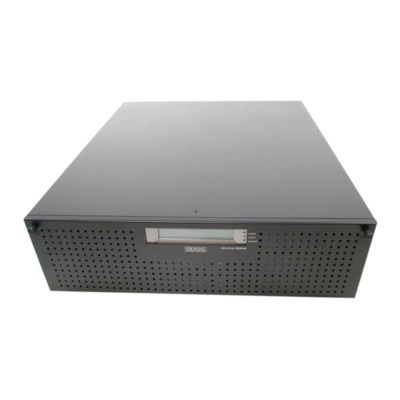
Chapter 1: Introduction Thank you for purchasing Promise Technology’s UltraTrak, external disk array system. This manual covers the full UltraTrak line, including these models: RM4000 • SX4000 • RM8000 • • SX8000 • RM15000 UltraTrak provides data storage solutions for applications where fault tolerance and data redundancy are required. -
Page 10: Features And Benefits
UltraTrak Series User Manual Features and Benefits Feature Benefit Maximum fault tolerance Ensures uninterrupted data availability. Supports RAID levels 0, 1, Allows system to be tuned for maximum 3, 5, 0+1 and JBOD performance. Supports RAID levels 30 Applies to the RM8000, SX8000 and RM15000. and 50 S.M.A.R.T Warns of disk drive degradation and potential... -
Page 11: Chapter 2: Rm4000 Setup
Chapter 2: RM4000 Setup Getting started with the UltraTrak RM4000 consists of the following steps: Unpack the UltraTrak storage subsystem (see below). Mount UltraTrak RM4000 in a rack (page 4). Install Hard Drives (page 5). Connect the SCSI Cables (page 9). SCSI Termination (page 10). -
Page 12: Mount Ultratrak Rm4000 In Rack
UltraTrak Series User Manual Mount UltraTrak RM4000 in Rack The UltraTrak may be installed in any convenient location within the LVD SCSI cable length distance of the next SCSI device. The UltraTrak RM4000 is designed specifically for rackmount installation but may also serve on a bench top as well. -
Page 13: Install Hard Drives
Chapter 2: RM4000 Setup Install Hard Drives Before using the UltraTrak you must first populate it with ATA hard drives. The UltraTrak RM4000 can support up to four (4) hard drives and provide the configurations listed below. Number of Hard Drives RAID Configuration Minimum Maximum... - Page 14 UltraTrak Series User Manual Locked Unlocked Front Panel Lock Figure 3. UltraTrak front panel access. Front Panel Drive Latch Handle Figure 4. UltraTrak disk drive access.
- Page 15 Chapter 2: RM4000 Setup Install new hard drives into the UltraTrak by doing the following: Unlock and open the Front Panel Door (see Figure 3) on the UltraTrak. Pull the Drive Carrier Latch Handle and remove an unused Drive Carrier (see Figure 4) from the UltraTrak.
- Page 16 UltraTrak Series User Manual Important Be sure each drive is securely fastened to its carrier. Proper installation ensures adequate grounding and minimizes vibration. Do not install drives with fewer than four screws. Figure 6. RM4000 drives are numbered right to left. Caution If you plan to operate your UltraTrak with less than four hard disk drives, install all four Drive Carriers into the Chassis, even if they...
-
Page 17: Connect The Scsi Cables
Chapter 2: RM4000 Setup Connect the SCSI Cables Installation of the UltraTrak disk array is very similar to the installation of a standard SCSI drive. The SCSI connector accepts the standard 68-pin LVD SCSI connector used on most LVD SCSI devices. Refer to your system and/or SCSI host adapter manual for additional installation procedures that may apply to your system or host adapter. -
Page 18: Scsi Termination
UltraTrak Series User Manual SCSI Termination Two 68-pin wide SCSI connectors are provided on the back of the enclosure for connecting the array to the system. These connectors are used in one of two ways: If the UltraTrak disk array is the only external SCSI device, or is the last •... -
Page 19: Daisy Chaining Multiple Ultratraks
Chapter 2: RM4000 Setup SCSI Output SCSI Terminator Connector Figure 8. SCSI Terminator Installation. Daisy Chaining Multiple UltraTraks Use a standard 68-pin SCSI-3 cable assembly to attach the array to the SCSI chain. Attach each cable to the individual units to be connected on the SCSI bus. -
Page 20: Daisy Chaining With Other Scsi Devices
UltraTrak Series User Manual Daisy Chaining with Other SCSI Devices This procedure is essentially the same as the procedure outlined above for multiple arrays. Refer to the manual associated with the other device or devices for additional information that may be pertinent to that unit. Ensure that each device has a unique SCSI ID (see page 17) and that only the first and last devices are terminated. -
Page 21: Connect The Power
Chapter 2: RM4000 Setup Connect the Power Warning Power supplies can contain over 240 volts. This high voltage, if mishandled, can cause serious injury or death. Do not touch or handle a power cable or power supply unless you have been trained and prepared to perform this task. UltraTrak systems will operate on either 115 volts AC or 230 volts AC. -
Page 22: Enter Or Change The Password
UltraTrak Series User Manual Enter or Change the Password The front panel interface for the UltraTrak consist of following items: Lock Liquid Crystal Display Power Status SCSI EXIT Activity Select Down Exit Figure 12. RM4000 Front Panel Display and Controls. Enter Password You are prompted to enter the correct password each time you access the UltraTrak Configuration mode. -
Page 23: Create Your First Array
Chapter 2: RM4000 Setup Create Your First Array The following procedures provide the basic steps needed to create an array and get your UltraTrak running quickly. Before beginning, you need to decide if you will create an array using the automatic setup features or if you will create the array manually. -
Page 24: Create An Array Manually
UltraTrak Series User Manual Press SEL to create the array or press EXIT to cancel. If you created a RAID 0+1, 3, 5, 30 or 50 array, UltraTrak will initialize your array. The LCD screen displays the progress. This process can take some time to finish, depending on the size of the disk drives in your array. -
Page 25: Assign A Scsi Id Or Lun
Chapter 2: RM4000 Setup 15. Press ! to move to Save Changes, then press SEL. 16. Press SEL to create the array or press EXIT to cancel. If you created a RAID 0+1, 3, 5, 30 or 50 array and set Initialization to ON, UltraTrak will initialize your array. - Page 26 UltraTrak Series User Manual Figure 14. SCSI BIOS screen with UltraTrak set to LUN mode. When UltraTrak is running in LUN mode, UltraTrak takes one SCSI address, as shown above. The arrays and the Promise RAID Console take LUN numbers. For UltraTrak, the default Mode is ID and the default ID setting is 0.
-
Page 27: Activate In-Band Scsi
Chapter 2: RM4000 Setup Activate In-Band SCSI In order to use the In-Band SCSI feature on UltraTrak, you must Enable SCSI Base Management on the UltraTrak. To change the SCSI Base Management setting, do the following: From the Idle mode display, press the SEL button on the front panel. Press the ! button once to move to Configuration, then press SEL to select Enter the password at the prompt (see Enter Password on page 14). -
Page 28: Install The Promise Raid Console Inf File (Windows Only)
UltraTrak Series User Manual Install the Promise RAID Console INF File (Windows only) Follow the procedure below to install the Promise RAID Console information (INF) file onto your RAID/Host PC running Windows. This procedure does not apply to other operating systems. Boot the UltraTrak(s) and be sure SCSI Base Mgt. -
Page 29: Chapter 3: Rm8000 Setup
Chapter 3: RM8000 Setup Getting started with the UltraTrak RM8000 consists of the following steps: Unpack the UltraTrak storage subsystem (see below). Mount UltraTrak RM8000 in a rack (page 22). Install Hard Drives (page 24). Connect the SCSI Cables (page 28). SCSI Termination (page 29). -
Page 30: Mount Ultratrak Rm8000 In Rack
UltraTrak Series User Manual Mount UltraTrak RM8000 in Rack The UltraTrak may be installed in any convenient location within the LVD SCSI cable length distance of the next SCSI device. The UltraTrak RM8000 is designed specifically for rack mount installation but may also serve on a bench top as well. - Page 31 Chapter 3: RM8000 Setup Front Door UltraTrak Front Door Release Screw RM8000 Release Screw POWER STATUS SCSI BUS UltraTrak RM 8000 Rack Vertical Post Rackmounting Tray or Shelf Figure 17. Rack Mounted RM8000.
-
Page 32: Install Hard Drives
UltraTrak Series User Manual Install Hard Drives Before using the UltraTrak you must first populate it with ATA hard drives. The UltraTrak RM8000 can support up to eight (8) hard drives and provide the configurations listed below. Number of Hard Drives RAID Configuration Minimum Maximum... - Page 33 Chapter 3: RM8000 Setup Locked / On Unlocked Drive Carrier Lock Figure 18. UltraTrak drive carrier lock. Figure 19. With the carrier unlocked, swing the handle to the left and pull the carrier out of the chassis.
- Page 34 UltraTrak Series User Manual Install new hard drives into the UltraTrak by doing the following: Loosen the two screws at the upper corners of the Front Panel Door and open it (see Figure 17). Insert the key into the drive carrier you want to remove and turn the key clockwise to unlock it (see Figure 18).
- Page 35 Chapter 3: RM8000 Setup Slide the assembled Drive Carrier back into the chassis and press the handle forward to lock the Drive Carrier. Repeat steps 2 through 7 until all of your hard drives are installed. Important Be sure each drive is securely fastened to its carrier. Proper installation ensures adequate grounding and minimizes vibration.
-
Page 36: Connect The Scsi Cables
UltraTrak Series User Manual Connect the SCSI Cables Installation of the UltraTrak disk array is very similar to the installation of a standard SCSI drive. The SCSI connector accepts the standard 68-pin LVD SCSI connector used on most LVD SCSI devices. Refer to your system and/or SCSI host adapter manual for additional installation procedures that may apply to your system or host adapter. -
Page 37: Scsi Termination
Chapter 3: RM8000 Setup SCSI Termination Two 68-pin wide SCSI connectors are provided on the back of the enclosure for connecting the array to the system. These connectors are used in one of two ways: If the UltraTrak disk array is the only external SCSI device, or is the last •... -
Page 38: Scsi Terminator
UltraTrak Series User Manual SCSI Terminator When the UltraTrak is the last SCSI device in the chain you must install the Promise-supplied (or equivalent) external SCSI terminator on the SCSI Output Connector (see below). SCSI Terminator SCSI Output Connector Figure 23. SCSI Terminator Installation. -
Page 39: Daisy Chaining Multiple Ultratraks
Chapter 3: RM8000 Setup Daisy Chaining Multiple UltraTraks Use a standard 68-pin SCSI-3 cable assembly to attach the array to the SCSI chain. Attach each cable to the individual units to be connected on the SCSI bus. Ensure that each device has a unique SCSI ID (see page 34) and that the last UltraTrak has a terminator. -
Page 40: Daisy Chaining With Other Scsi Devices
UltraTrak Series User Manual Daisy Chaining with Other SCSI Devices This procedure is essentially the same as the procedure outlined above for multiple arrays. Refer to the manual associated with the other device or devices for additional information that may be pertinent to that unit. Ensure that each device has a unique SCSI ID (see page 38) and that only the first and last devices are terminated. -
Page 41: Connect The Power
Chapter 3: RM8000 Setup Connect the Power Warning Power supplies can contain over 240 volts. This high voltage, if mishandled, can cause serious injury or death. Do not touch or handle a power cable or power supply unless you have been trained and prepared to perform this task. The UltraTrak RM8000 includes two replaceable power supply modules. -
Page 42: Enter Or Change The Password
UltraTrak Series User Manual Enter or Change the Password The front panel interface for the UltraTrak consist of following items: Liquid Crystal Display Power Status SCSI Activity EXIT Select Down Exit Figure 27. RM8000 Front Panel Display and Controls. Enter Password You are prompted to enter the correct password each time you access the UltraTrak Configuration mode. -
Page 43: Your First Array
Chapter 3: RM8000 Setup Change Password You may change the password by doing the following procedure: From the Idle mode display, press the ! button to select Change Password. Press the SEL button. Enter Old Password. Enter New Password. Press Exit at the New password saved prompt. Your First Array The following procedures provide the basic steps needed to create an array and get your UltraTrak running quickly. -
Page 44: Create An Array Manually
UltraTrak Series User Manual At Configure Array, press SEL. At Array Setup, press SEL. Note: If the message “*No Free Disk” appears, it means no free disk drives are present. There could be an array or the drives are not yet installed. See Delete an Array in Chapter 6 and Install Hard Drives above for more information. - Page 45 Chapter 3: RM8000 Setup 11. At Gigabyte Boundary, press SEL to toggle between ON and OFF. 12. Press ! to move to Add/Remove Drives, then press SEL to enter. 13. Press " and ! to move to each drive. Press SEL to toggle between Free and Assigned.
-
Page 46: Assign A Scsi Id Or Lun
UltraTrak Series User Manual Assign a SCSI ID or LUN Each device on a SCSI chain must have a unique ID. The number of devices on your SCSI bus will determine which SCSI Mode you select for UltraTrak. UltraTrak has two SCSI ID modes, ID and LUN (Logical Unit Number): ID mode assigns a separate SCSI ID number to each array. - Page 47 Chapter 3: RM8000 Setup From the Idle mode display, press the SEL button on the front panel. Press the ! button once to move to Configuration, then press SEL to enter. Enter the password at the prompt (see Enter Password on page 34). At the Configuration menu, press ! to move to Configure SCSI, then press SEL to enter.
-
Page 48: Activate In-Band Scsi
UltraTrak Series User Manual Activate In-Band SCSI In order to use the In-Band SCSI feature on UltraTrak, you must Enable SCSI Base Management on the UltraTrak. To change the SCSI Base Management setting, do the following: From the Idle mode display, press the SEL button on the front panel. Press the ! button once to move to Configuration, then press SEL to enter. -
Page 49: Install The Promise Raid Console Inf File (Windows Only)
Chapter 3: RM8000 Setup Install the Promise RAID Console INF File (Windows only) Follow the procedure below to install the Promise RAID Console information (INF) file onto your RAID/Host PC running Windows. This procedure does not apply to other operating systems. Boot the UltraTrak(s) and be sure SCSI Base Mgt. - Page 50 UltraTrak Series User Manual...
-
Page 51: Chapter 4: Sx4000 And Sx8000 Setup
Chapter 4: SX4000 and SX8000 Setup Getting started with the UltraTrak consists of the following steps: Unpack the UltraTrak storage subsystem (see below). Install Hard Drives (page 44). Connect the SCSI Cables (page 48). SCSI Termination (page 49). Connect the Power (page 53). Enter or Change the Password (page 54). -
Page 52: Install Hard Drives
UltraTrak Series User Manual Install Hard Drives Before using the UltraTrak you must first populate it with ATA hard drives. The UltraTrak SX4000 can support up to four (4) hard drives while the UltraTrak SX8000 can support up to eight (8). They can provide the configurations listed below. - Page 53 Chapter 4: SX4000/8000 Setup Locked / On Unlocked Drive Carrier Lock Figure 31. UltraTrak drive carrier lock. Figure 32. With the carrier unlocked, swing the handle to the left and pull the carrier out of the chassis (SX4000 shown).
- Page 54 UltraTrak Series User Manual Install new hard drives into the UltraTrak by doing the following: Open the Front Panel door. Insert the key into the drive carrier you want to remove and turn the key clockwise to unlock it (see Figure 31). Then gently pull the carrier out of the housing.
- Page 55 Chapter 4: SX4000/8000 Setup Slide the assembled Drive Carrier back into the chassis and press the handle forward to lock the Drive Carrier. Repeat steps 2 through 7 until all of your hard drives are installed. Important Be sure each drive is securely fastened to its carrier. Proper installation ensures adequate grounding and minimizes vibration.
-
Page 56: Connect The Scsi Cables
UltraTrak Series User Manual Connect the SCSI Cables Installation of the UltraTrak disk array is very similar to the installation of a standard SCSI drive. The SCSI connector accepts the standard 68-pin LVD SCSI connector used on most LVD SCSI devices. Refer to your system and/or SCSI host adapter manual for additional installation procedures that may apply to your system or host adapter. -
Page 57: Scsi Termination
Chapter 4: SX4000/8000 Setup SCSI Termination Two 68-pin wide SCSI connectors are provided on the back of the enclosure for connecting the array to the system. These connectors are used in one of two ways: If the UltraTrak disk array is the only external SCSI device, or is the last •... -
Page 58: Scsi Terminator
UltraTrak Series User Manual SCSI Terminator When the UltraTrak is the last SCSI device in the chain you must install the Promise-supplied (or equivalent) external SCSI terminator on the SCSI Output Connector (see below). SCSI IN SCSI OUT /TERM SX4000 SCSI Output Connector SCSI Terminator SCSI-IN... -
Page 59: Daisy Chaining Multiple Ultratraks
Chapter 4: SX4000/8000 Setup Daisy Chaining Multiple UltraTraks Use a standard 68-pin SCSI-3 cable assembly to attach the array to the SCSI chain. Attach each cable to the individual units to be connected on the SCSI bus. Ensure that each device has a unique SCSI ID (see page 58) and that the last UltraTrak has a terminator. -
Page 60: Daisy Chaining With Other Scsi Devices
UltraTrak Series User Manual Daisy Chaining with Other SCSI Devices This procedure is essentially the same as the procedure outlined above for multiple arrays. Refer to the manual associated with the other device or devices for additional information that may be pertinent to that unit. Ensure that each device has a unique SCSI ID (see page 58) and that only the first and last devices are terminated. -
Page 61: Connect The Power
Chapter 4: SX4000/8000 Setup Connect the Power Warning Power supplies can contain over 240 volts. This high voltage, if mishandled, can cause serious injury or death. Do not touch or handle a power cable or power supply unless you have been trained and prepared to perform this task. The UltraTrak SX8000 includes two replaceable power supply modules. -
Page 62: Enter Or Change The Password
UltraTrak Series User Manual Enter or Change the Password The front panel interface for the UltraTrak consist of following items: Liquid Crystal Display Status ARRAY SCSI BUS SCSI Activity EXIT Select Down Exit Figure 40. SX4000 and SX8000 Front Panel Display and Controls. Enter Password You are prompted to enter the correct password each time you access the UltraTrak Configuration mode. - Page 63 Chapter 4: SX4000/8000 Setup Change Password You may change the password by doing the following procedure: From the Idle mode display, press the ! button to select Change Password. Press the SEL button. Enter Old Password. Enter New Password. Press Exit at the New password saved prompt.
-
Page 64: Your First Array
UltraTrak Series User Manual Your First Array The following procedures provide the basic steps needed to create an array and get your UltraTrak running quickly. Before beginning, you need to decide if you will create an array using the automatic setup features or if you will create the array manually. -
Page 65: Create An Array Manually
Chapter 4: SX4000/8000 Setup Press SEL to create the array or press EXIT to cancel. If you created a RAID 0+1, 3, 5, 30 or 50 array, UltraTrak will initialize your array. The LCD screen displays the progress. This process can take some time to finish, depending on the size of the disk drives in your array. -
Page 66: Assign A Scsi Id Or Lun
UltraTrak Series User Manual 15. Press ! to move to Save Changes, then press SEL to select. 16. Press SEL again to create the array or press EXIT to cancel. If you created a RAID 0+1, 3, 5, 30 or 50 array and set Initialization to ON, UltraTrak will initialize your array. - Page 67 Chapter 4: SX4000/8000 Setup Figure 42. SCSI BIOS screen with UltraTrak set to LUN mode. When UltraTrak is running in LUN mode, UltraTrak takes one SCSI address, as shown above. The arrays and the Promise RAID Console take LUN numbers. For UltraTrak, the default Mode is ID and the default ID setting is 0.
-
Page 68: Activate In-Band Scsi
UltraTrak Series User Manual Activate In-Band SCSI In order to use the In-Band SCSI feature on UltraTrak, you must Enable SCSI Base Management on the UltraTrak. To change the SCSI Base Management setting, do the following: From the Idle mode display, press the SEL button on the front panel. Press the ! button once to move to Configuration, then press SEL to enter. -
Page 69: Install The Promise Raid Console Inf File (Windows Only)
Chapter 4: SX4000/8000 Setup Install the Promise RAID Console INF File (Windows only) Follow the procedure below to install the Promise RAID Console information (INF) file onto your RAID/Host PC running Windows. This procedure does not apply to other operating systems. Boot the UltraTrak(s) and be sure SCSI Base Mgt. - Page 70 UltraTrak Series User Manual...
-
Page 71: Chapter 5: Rm15000 Setup
Chapter 5: RM15000 Setup Getting started with the UltraTrak consists of the following steps: Unpack the UltraTrak storage subsystem (see below). Mount UltraTrak RM15000 in a rack (page 64). Install Hard Drives (page 65). Connect the SCSI Cables (page 69). SCSI Termination (page 69). -
Page 72: Mount Ultratrak Rm15000 In Rack
UltraTrak Series User Manual Mount UltraTrak RM15000 in Rack The UltraTrak may be installed in any convenient location within the LVD SCSI cable length distance of the next SCSI device. The UltraTrak RM15000 is designed specifically for rackmount installation but may also serve on a bench top as well. -
Page 73: Install Hard Drives
Chapter 5: RM15000 Setup Install Hard Drives Before using the UltraTrak you must first populate it with ATA hard drives. The UltraTrak RM15000 can support up to fifteen hard drives and provide the configurations listed below. Number of Hard Drives RAID Configuration Minimum Maximum... - Page 74 UltraTrak Series User Manual Unlocked Locked Front Panel Lock Figure 44. UltraTrak Front Panel access. Drive Latch Front Handle Panel Figure 45. UltraTrak RM15000 Disk Drive access.
- Page 75 Chapter 5: RM15000 Setup Install new hard drives into the UltraTrak by doing the following: Unlock and open the Front Panel Door (see Figure 44) on the UltraTrak. Pull the Drive Carrier Latch Handle and remove an unused Drive Carrier (see Figure 45) from the UltraTrak.
- Page 76 UltraTrak Series User Manual Important Be sure each drive is securely fastened to its carrier. Proper installation ensures adequate grounding and minimizes vibration. Do not install drives with fewer than four screws. Figure 47. RM15000 Drives are numbered left to right. Caution If you plan to operate your UltraTrak with less than 15 hard disk drives, install all 15 Drive Carriers into the enclosure, even if they...
-
Page 77: Connect The Scsi Cables
Chapter 5: RM15000 Setup Connect the SCSI Cables Installation of the UltraTrak disk array is very similar to the installation of a standard SCSI drive. The SCSI connector accepts the standard 68-pin LVD SCSI connector used on most LVD SCSI devices. Refer to your system and/or SCSI host adapter manual for additional installation procedures that may apply to your system or host adapter. -
Page 78: Scsi Terminator
UltraTrak Series User Manual terminator is required at the RM4000 but the last device in the daisy chain must have a terminator. Correct SCSI termination procedures require that the first and last devices on the SCSI bus be terminated. If the first or last device is not terminated, or if devices other than the first and last are terminated, erratic SCSI bus performance may occur. -
Page 79: Daisy Chaining Multiple Ultratraks
Chapter 5: RM15000 Setup Daisy Chaining Multiple UltraTraks Use a standard 68-pin SCSI-3 cable assembly to attach the array to the SCSI chain. Attach each cable to the individual units to be connected on the SCSI bus. Ensure that each device has a unique SCSI ID (see page 78) and that the last UltraTrak has a terminator. -
Page 80: Daisy Chaining With Other Scsi Devices
UltraTrak Series User Manual Daisy Chaining with Other SCSI Devices This procedure is essentially the same as the procedure outlined above for multiple arrays. Refer to the manual associated with the other device or devices for additional information that may be pertinent to that unit. Ensure that each device has a unique SCSI ID (see page 78) and that only the first and last devices are terminated. -
Page 81: Connect The Power
Chapter 5: RM15000 Setup Connect the Power Warning Power supplies can contain over 240 volts. This high voltage, if mishandled, can cause serious injury or death. Do not touch or handle a power cable or power supply unless you have been trained and prepared to perform this task. UltraTrak systems will operate on either 115 volts AC or 230 volts AC. -
Page 82: Enter Or Change The Password
UltraTrak Series User Manual Disk Drive LED View Ports EXIT LCD Display LED Display Figure 53. UltraTrak RM15000 Displays. The UltraTrak spins up the disk drives sequentially in order to equalize power draw during start-up. After a few moments the LCD should display a message similar to the following: No Array is defined 30°C/86°F... - Page 83 Chapter 5: RM15000 Setup Enter Password You are prompted to enter the correct password each time you access the UltraTrak Configuration mode. A password consists of four digits. The default password is 0000. The active password digit is marked by Please Enter Password: an underscore.
-
Page 84: Your First Array
UltraTrak Series User Manual Your First Array The following procedures provide the basic steps needed to create an array and get your UltraTrak running quickly. Before beginning, you need to decide if you will create an array using the automatic setup features or if you will create the array manually. -
Page 85: Create An Array Manually
Chapter 5: RM15000 Setup Press SEL to create the array or press EXIT to cancel. If you created a RAID 0+1, 3, 5, 30 or 50 array, UltraTrak will initialize your array. The LCD screen displays the progress. This process can take some time to finish, depending on the size of the disk drives in your array. -
Page 86: Assign A Scsi Id Or Lun
UltraTrak Series User Manual 15. Press ! to move to Save Changes, then press SEL to select it. 16. Press SEL again to create the array or press EXIT to cancel. If you created a RAID 0+1, 3, 5, 30 or 50 array and set Initialization to ON, UltraTrak will initialize your array. - Page 87 Chapter 5: RM15000 Setup Figure 56. SCSI BIOS screen with UltraTrak set to LUN mode. When UltraTrak is running in LUN mode, UltraTrak takes one SCSI address, as shown above. The arrays and the Promise RAID Console take LUN numbers. For UltraTrak, the default Mode is ID and the default ID setting is 0.
-
Page 88: Activate In-Band Scsi
UltraTrak Series User Manual Activate In-Band SCSI In order to use the In-Band SCSI feature on UltraTrak, you must Enable SCSI Base Management on the UltraTrak. To change the SCSI Base Management setting, do the following: From the Idle mode display, press the SEL button on the front panel. Press the ! button once to move to Configuration, then press SEL to enter. -
Page 89: Install The Promise Raid Console Inf File (Windows Only)
Chapter 5: RM15000 Setup Install the Promise RAID Console INF File (Windows only) Follow the procedure below to install the Promise RAID Console information (INF) file onto your RAID/Host PC running Windows. This procedure does not apply to other operating systems. Boot the UltraTrak(s) and be sure SCSI Base Mgt. - Page 90 UltraTrak Series User Manual...
-
Page 91: Chapter 6: Array Maintenance
Chapter 6: Array Maintenance Drive Status Indicators As shown in the figure below, each drive has three status LEDs. Power Status Disk Activity Figure 58. RM4000 and RM15000 Drive Status Indicators. Power Status Disk Activity Figure 59. SX4000, SX8000 and RM8000 Drive Status Indicators. Meaning of Status Indicators Indicator Color... -
Page 92: Critical & Offline Arrays
UltraTrak Series User Manual Critical & Offline Arrays A fault tolerant array (all levels except RAID 0 and JBOD) goes critical when a drive is removed or fails. Due to the fault tolerance of the array, the data is still available and online. -
Page 93: Replacing A Disk Drive
Important If the replacement drive was formerly part of another array, Promise Technology recommends wiping the reserve sector on the drive rather than merely deleting the previous array information. Before Reconstruction begins, see Wipe Out Disk on page 116 for more details. - Page 94 UltraTrak Series User Manual Do the following to replace a hard drive. See the illustrations under Install Hard Drives in Chapters 2, 3, 4 and 5). Open the Front Panel on the UltraTrak. Find the drive you wish to remove. Pull the handle to release the Drive Carrier (RM4000, RM15000).
-
Page 95: Expanding An Array
Chapter 6: Array Maintenance Expanding an Array Expanding an array increases the array capacity without affecting data availability. You can expand an existing array by adding one or more free disk drives to the array using the Expand Array function. Note With most operating systems, expanding an array will require you to partition the added space with a new drive letter. -
Page 96: Raid Conversion
UltraTrak Series User Manual RAID Conversion Existing arrays can be converted to a different RAID level of equal or greater capacity to add flexibility, redundancy or for tuning an array for a different storage application. UltraTrak supports the following conversions, except for RM4000 and SX4000 which do not support RAID 30 and RAID 50. - Page 97 Chapter 6: Array Maintenance From Comments RAID 1 RAID 50 Increases performance. 6, 8, 10, 12 or 14 drives RAID 30 required. RAID 5 Adds performance, capacity and redundancy. 3 or more drives required. RAID 3 RAID 0+1 Adds performance and capacity. 4, 6, 8, 10, 12 or 14 drives required.
-
Page 98: Convert An Array
UltraTrak Series User Manual Convert an Array Do the following steps to convert an array: Press the SEL button on the front panel. Press the ! button once to select Configuration then press SEL to open. Enter your password at the prompt. At Configure Array, press SEL. -
Page 99: Chapter 7: Front Panel Interface
Chapter 7: Front Panel Interface The front panel interface for the UltraTrak consist of following items: Liquid Crystal Display Power Status SCSI Activity EXIT Select Down Exit Figure 60. RM4000 and RM15000 Front Panel Display and Controls. Liquid Crystal Display Status ARRAY SCSI BUS... - Page 100 UltraTrak Series User Manual Liquid Crystal Display Power Status SCSI Activity EXIT Select Down Exit Figure 62. RM8000 Front Panel Display and Controls. Type of Interface Name Comments LED Indicators Power Indicator Power Activity Indicator Status Green Enclosure functioning normally. Amber An array is critical, a power supply has failed, or a fan has failed.
-
Page 101: The Lcd Messages
Chapter 7: Front Panel Interface Type of Interface Name Comments " Control Buttons Press this button to scroll any available messages up through the LCD and activates a message for the Select button. Press this button to scroll any available messages down through the LCD and activates a message for the Select button. -
Page 102: Idle Mode
UltraTrak Series User Manual Idle Mode The Idle mode message, such as shown below, is displayed during normal operation of the UltraTrak when there are no problems or buttons being pressed: Array status may be: Array Functional Array Functional • 30°C/86°F 4500RPM •... - Page 103 Chapter 7: Front Panel Interface The second line of the Idle mode menu can also provide the following error information: 30°C/86°F 4500 RPM Enclosure working normally • Array Rebuilding xx% At least one array is rebuilding • Array Synchronizing xx% At least one array is synchronizing •...
-
Page 104: Initial Mode Menu
UltraTrak Series User Manual Initial Mode See page 99 View Status View Controller Info View Cache Stats View Array Information View Enclosure See page 98 Configuration Configure Array Configure Cache Configure SCSI See pages 14, 34, 54 or 74 Change Password Initial Mode Menu You may select one of the following functions from the Initial mode menu: View Status... - Page 105 Chapter 7: Front Panel Interface Configuration Configure Array See page 104 Auto Array Setup View Drive Assignments Define Array Delete Array Expand Array RAID Conversion Advanced Feature Configure Cache See page 121 Write Cache Read Ahead Cache Flush Frequency Configure SCSI See page 122 Mode SCSI ID...
-
Page 106: Configuration Menu
UltraTrak Series User Manual Configuration Menu You enter the Configuration mode after entering the correct password. In Configuration mode you may view the status of the UltraTrak system and configure both UltraTrak hardware and arrays. The main configuration menu allows the user to select the following menus: Configure Array Configure Cache Press "... - Page 107 Chapter 7: Front Panel Interface View Status See page 100 View Controller Info Memory Size Hardware Rev Firmware Rev See page 101 View Cache Stats See page 42 Cache Memory Size Cache Block Size Cache Read Hit Cache Write Hit See page 102 View Array Information Array x Size...
-
Page 108: View Status Menu
UltraTrak Series User Manual View Status Menu The View Status menu allows the user to select the information he wishes to view with the following menu: View Controller Info. View Cache Stats Press " or ! to move these items on the View Array Information LCD. - Page 109 Chapter 7: Front Panel Interface View Cache Stats The View Cache Stats mode displays the cache memory size, cache block size; the cache read hit percentage rate and the cache write hit percentage rate. Where the values shown are simply Cache Mem Size: 64 MB examples.
- Page 110 UltraTrak Series User Manual View Array Information The View Array Information mode displays the array ID, array size, RAID level and array status (Functional, Critical, Offline, Rebuilding, Synchronizing and Initializing). If these modes of display require more than 2 lines to display information press the up and down keys to scroll the display.
- Page 111 Chapter 7: Front Panel Interface View Enclosure The View Enclosure menu displays the following information: Where the values shown are simply Temp1: 30°C/86°F examples. Temp2: 30°C/86°F Press " or ! to move these items on the Temp3: 30°C/86°F LCD. FAN 1: 4782 RPM …...
- Page 112 UltraTrak Series User Manual Configure Array Auto Array Setup See page 106 Displays a list of the available RAID levels See page 108 View Drive Assignments Displays a list of the installed disk drives Define Array See page 109 RAID Level Stripe Block Size Gigabyte Boundary Add/Remove Drives...
-
Page 113: Configure Array
Chapter 7: Front Panel Interface Configure Array The Configure Array menu will allow the creation and deletion of arrays. The configure array menu contains the following sub menus: Auto Array Setup View Drive Assignments Press " or ! to move these items on the Define Array LCD. - Page 114 UltraTrak Series User Manual Auto Array Setup Function Caution RAID 0+1, 3, 5, 30 and 50 arrays created automatically will be initialized. Any data on the drives will be erased. If you are using disk drives that could have important data on them, make a backup copy of the data before installing the drives in the UltraTrak.
- Page 115 Chapter 7: Front Panel Interface You will see the following choice after you have selected a RAID level: Press SEL to Create Press EXIT to Cancel What you can do: Press SEL: Press SEL to create the array. Press SEL again to reboot the UltraTrak. Press ": Does nothing.
- Page 116 UltraTrak Series User Manual View Drive Assignments The View Drive Assignments mode lists each installed drive by model and identifies its array ID or that it is free (if it is not assigned to an array). Each drive is displayed on one line. 1 MAXTOR Asgn In Ary 1 Where the values shown are simply examples.
- Page 117 Chapter 7: Front Panel Interface Define Array The Define Array menu allows you to specify the parameters for the array you are about to create. Begin at the top item, RAID Level, and work your way down to Save Changes. See Chapter 8: Technology Background for more help in choosing the RAID Levels and array parameters best suited for your requirements.
- Page 118 UltraTrak Series User Manual You will see the following message if there are no free disks available to build a new array: No free disk What you can do: Press SEL: Pressing SEL will save the array. Press ": Does nothing. Press !: Does nothing.
- Page 119 Chapter 7: Front Panel Interface Save Changes Menu This menu appears after you Create, Expand or Convert an array. Press SEL to Create/Expand/Conv Press EXIT to Cancel What you can do: Press SEL: Press SEL will Create, Expand or Convert your array. Press SEL again to restart UltraTrak.
- Page 120 UltraTrak Series User Manual Delete Array The Delete Array menu allows the user to select an array and delete the configuration information for that array. This action will free all drives that have been assigned to that array. Array ID: 1 Only existing Array IDs are displayed.
- Page 121 Chapter 7: Front Panel Interface RAID Conversion The RAID Conversion menu allows the user to covert an exist array to a different RAID level. Source Array ID Target RAID Level Press " or ! to move these items on the Add New Drives LCD.
- Page 122 UltraTrak Series User Manual Add New Drives The Add New Drives menu lists the available free drives. Select the drives you wish to add. 3 VENDOR-U Free Only free drives are Displayed. 4 MAXTOR Free Press " or ! to move these items on the LCD.
- Page 123 Chapter 7: Front Panel Interface Advanced Feature Wipe Out Disk Synchronize Array Press " or ! to move these items on the Stop RAID Conversion LCD. Disable Buzzer Rebuild/Sync Pri. High Rebuild Media Err Skip Smart Check Enabled HD WriteCache Enabled HD Timeout: 07 sec HD Failure Retry: 04 What you can do:...
- Page 124 UltraTrak Series User Manual Wipe Out Disk The Wipe Out Disk menu allows the user to delete the area on the hard drive that contains array information used exclusively by the UltraTrak controller. It may be necessary to wipe out a disk if the disk was previously a member of an UltraTrak array and you wish to use the disk in a different UltraTrak array.
- Page 125 (Active is marked by *.) Press EXIT: Returns to the Advanced Feature menu. Note Promise Technology suggests synchronizing an array once a month. Synchronization is a preventative maintenance measure used to avoid problems with data integrity. Synchronizing simply recalculates redundant data (similar to...
- Page 126 UltraTrak Series User Manual Rebuild/Sync Pri. Assigns the priority that UltraTrak gives to rebuilding/synchronizing data in the background. A High setting assigns most of UltraTrak’s resources to the rebuild process at the expense of responding to ongoing read/write data requests by the operating system.
- Page 127 Chapter 7: Front Panel Interface Smart Check SMART is Self-Monitoring Analysis and Reporting Technology, a function of the disk drives that gathers performance information used to predict a pending drive failure. With this option enabled, the Controller will check the status of the disk drives and report any problems.
- Page 128 UltraTrak Series User Manual HD Timeout The HD Timeout sets the amount of time a disk drive has to respond to a command before UltraTrak sends a retry command. The number of retries depends on the HD Retry Count setting, below. The timeout period ranges from 0 to 39 seconds.
-
Page 129: Configure Cache
Chapter 7: Front Panel Interface Configure Cache Write Cache Write Back Write Thru Cache Flush Frequency default Configure Cache The Configure Cache menu will allow the setting of cache parameters. The following parameter is set in the Configure Cache menu: Write Cache: Write Thru Cache Flush Frequency What you can do:... -
Page 130: Configure Scsi
UltraTrak Series User Manual Configure SCSI Mode See page 123 See page 124 SCSI ID Lists SCSI IDs from 0 thru 15 for user selection. See page 125 SCSI Base Mgt. Configure SCSI The Configure SCSI menu will allow the setting of SCSI parameters. The following parameters are set in the Configure SCSI menu: Mode SCSI ID... - Page 131 Chapter 7: Front Panel Interface Mode Select one of the following SCSI ID modes: Selected Press SEL to toggle between these two modes. What you can do: Press SEL: Selects one of the following active functions: Select device ID mode. Select LUN (logical unit number) mode.
- Page 132 UltraTrak Series User Manual SCSI ID Select a SCSI ID between 0 and 15: Selected Press " or ! to move these items on the LCD. … What you can do: Press SEL: Selects one of the following active functions: from a list of numbers Selects the SCSI ID –...
- Page 133 Chapter 7: Front Panel Interface SCSI Base Mgt. Enable the SCSI Base Management feature: SCSI ID SCSI Base Mgt. Enabled What you can do: Press SEL: Toggles between Enabled and Disabled. Press ": Moves the active message line up. (Active is marked by *.) Press !: Moves the active message line down.
- Page 134 UltraTrak Series User Manual...
-
Page 135: Chapter 8: Technology Background
Chapter 8: Technology Background This chapter consists of the following parts: Introduction to RAID (below) • Choosing a RAID Level (page 136) • Choosing Stripe Block Size (page139) • Gigabyte Boundary (page 139) • • Initialization (page 140) • Hot Spare Drive (page 140) Partition and Format Array (page 140) •... -
Page 136: Raid 0 - Striping
UltraTrak Series User Manual RAID 0 - Striping When a disk array is striped, the read and write blocks of data are interleaved between the sectors of multiple drives. Performance is increased, since the workload is balanced between drives or “members” that form the array. Identical drives are recommended for performance as well as data storage efficiency. -
Page 137: Raid 1 - Mirroring
Chapter 8: Technology Background RAID 1 - Mirroring When a disk array is mirrored, identical data is written to a pair of drives, while reads are performed in parallel. The reads are performed using elevator seek and load balancing techniques where the workload is distributed in the most efficient manner. -
Page 138: Raid 0+1 - Striping / Mirroring
UltraTrak Series User Manual RAID 0+1 - Striping / Mirroring Striping/mirroring combines both of the previous array types. It can increase performance by reading and writing data in parallel while protecting data with duplication. At least four drives are needed for RAID 0+1 to be installed. With a four-drive disk array, drive pairs are striped together with one pair mirroring the first pair. -
Page 139: Raid 3 - Block Striping With Dedicated Parity
Chapter 8: Technology Background RAID 3 - Block Striping with Dedicated Parity RAID level 3 organizes data across the physical drives of the array, and stores parity information on to a drive dedicated to this purpose. This organization allows increased performance by accessing multiple drives simultaneously for each operation, as well as fault tolerance by providing parity data. -
Page 140: Raid 5 - Block Striping With Distributed Parity
UltraTrak Series User Manual RAID 5 - Block Striping with Distributed Parity RAID 5 is similar to RAID 3 as described above except that the parity data is distributed across the physical drives along with the data blocks. In each case, the parity data is stored on a different disk than its corresponding data block. -
Page 141: Raid 30 - Striping Of Dedicated Parity Arrays
Chapter 8: Technology Background RAID 30 - Striping of Dedicated Parity Arrays RAID 30 combines both RAID 3 and RAID 0 features. Data is striped across disks as in RAID 0, and it uses dedicated parity as in RAID 3. RAID 30 provides data reliability, good overall performance and supports larger volume sizes. -
Page 142: Raid 50 - Striping Of Distributed Parity Arrays
UltraTrak Series User Manual RAID 50 - Striping of Distributed Parity Arrays RAID 50 combines both RAID 5 and RAID 0 features. Data is striped across disks as in RAID 0, and it uses distributed parity as in RAID 5. RAID 50 provides data reliability, good overall performance and supports larger volume sizes. -
Page 143: Jbod - Single Drive
Chapter 8: Technology Background JBOD - Single Drive An alternative to RAID, Just a Bunch of Disks (JBOD) capacity is equal to the sum of all drives in the group, even if the drives are of different sizes. JBOD appears in the User Interface as one or more individual drives. There are no performance or fault tolerance features. -
Page 144: Choosing A Raid Level
UltraTrak Series User Manual Choosing a RAID Level There are several issues to consider when choosing the RAID Level for your UltraTrak array. The following discussion summarizes some advantages, disadvantages and applications for each choice. RAID 0 Advantages Disadvantages Implements a striped disk array, the Not a true RAID because it is not data is broken down into blocks and fault-tolerant... -
Page 145: Raid 3
Chapter 6: Your First Array RAID 3 Advantages Disadvantages High Read data transfer rate Parity drive can become bottleneck if Disk failure has an insignificant impact a lot of data is being written to the on throughput array Recommended Applications for RAID 3 Image Editing •... -
Page 146: Raid 50
UltraTrak Series User Manual RAID 30 Characteristics/Advantages Disadvantages High Read data transaction rate Higher disk overhead than RAID 3 Medium Write data transaction rate Good aggregate transfer rate High reliability Supports large volume sizes Recommended Applications for RAID 30 File and Application servers •... -
Page 147: Jbod
Chapter 6: Your First Array JBOD Characteristics/Advantages Disadvantages Uses 100% capacity of all hard drives The failure of one drive will result in all data being lost on that drive Should not be used in mission critical environments Recommended Applications for JBOD File archiving •... -
Page 148: Initialization
UltraTrak Series User Manual Please note that users will lose a small amount of available storage capacity from each drives in order to arrive at a common drive size. Initialization Initialization is the process of setting all of the data bits on all of the disk drives to zero. -
Page 149: Chapter 9: In-Band Scsi
Chapter 9: In-Band SCSI In-Band SCSI enables a single PC to manage multiple UltraTraks in a SCSI chain by passing management commands though the SCSI bus, rather than the traditional serial cable. Currently, one PC can manage up to seven (7) UltraTraks using In-Band SCSI. The previous serial control connection allowed one PC to manage only one UltraTrak at a time. -
Page 150: Enable The Scsi Base Management Option
UltraTrak Series User Manual Enable the SCSI Base Management Option The SCSI Base Management Option must be enabled on your UltraTrak subsystem for In-Band SCSI to function. In-Band SCSI appears as SCSI Base Mgt. on the UltraTrak LCD screen. Be sure to check all of your UltraTraks. Press the SEL button on the front of the UltraTrak cabinet to access the system information in the LCD screen. -
Page 151: Install The Promise Raid Console Inf File (Windows Only)
Chapter 9: In-Band SCSI Install the Promise RAID Console INF File (Windows only) In-Band SCSI requires an Information (INF) file to install the Promise RAID Console into the Device Manager. Follow the procedure below to install the INF file on your RAID/Host PC running Windows. - Page 152 UltraTrak Series User Manual Figure 73. With the INF file correctly installed, Promise RAID Console appears under System devices in the Device Manager.
-
Page 153: Webpam
Chapter 9: In-Band SCSI WebPAM The Promise Technology’s Web-Based Promise Array Management (WebPAM) software is required for In-Band SCSI monitoring and operation. WebPAM ships on the software CD with the current line of UltraTraks. You can download it from the Promise website. -
Page 154: Verify In-Band Scsi Function
UltraTrak Series User Manual Verify In-Band SCSI Function After meeting the four requirements to enable In-Band SCSI on UltraTrak as described above, verify that the In-Band SCSI feature is working properly. Connect your UltraTrak and RAID/Host PC with the SCSI cable only. Disconnect the Serial (null-modem cable), if present. -
Page 155: Scsi Id Modes
Chapter 9: In-Band SCSI SCSI ID Modes UltraTrak has two SCSI ID modes, ID and LUN (Logical Unit Number). ID mode assigns a separate SCSI ID number to each array. • • LUN mode assigns one SCSI ID to the UltraTrak. The arrays are then numbered LUN 0, LUN 1, and so on. - Page 156 UltraTrak Series User Manual Note In the diagrams above, Promise RAID Console represents the UltraTrak In-band SCSI function.
-
Page 157: Chapter 10: Ultratrak Maintenance
Chapter 10: UltraTrak Maintenance Update UltraTrak Firmware Caution Promise recommends updating the UltraTrak firmware only if you are experiencing a problem that the firmware update addresses. Notes This procedure requires: A computer capable of booting from an MS-DOS diskette. • The null-modem cable that shipped with your UltraTrak or an •... - Page 158 UltraTrak Series User Manual 11. Power on the UltraTrak and watch the computer monitor. The following menu should display: Upload Image to UltraTrak Download Image to UltraTrak RESET FLASH EXIT 12. Press 2. (This is a safety precaution to ensure you have a copy of the current level firmware).
-
Page 159: Replace The Controller Card
Chapter 10: UltraTrak Maintenance Replace the Controller Card The controller card (circuit board) is accessible by removing the cover from the UltraTrak cabinet. The controller card is installed above the hard drives on SX models and behind the hard drives on RM models. UltraTrak How to remove the cover RM4000... -
Page 160: Install The Controller Card
UltraTrak Series User Manual LED/LCD Connector Jumpers Reset Button Serial Connector Slide Grip Slide Grip Mounting Bracket Set Screw SCSI Connector Memory Card Main Connector Figure 77. Key components of the UltraTrak controller card. Install the Controller Card Follow these instructions to install a controller card: Place the controller board onto the mounting bracket. -
Page 161: Reset To Default Password
Chapter 10: UltraTrak Maintenance Reset to Default Password This procedure will reset the UltraTrak’s password back to its default value of 0000. Main Connector Jumper on pins 1 and 2 Move the jumper to pins 2 and 3 to reset the password Figure 78. -
Page 162: Replace The Power Supply
UltraTrak Series User Manual Replace the Power Supply Warning Power supplies can contain over 240 volts. This high voltage, if mishandled, can cause serious injury or death. Do not touch or try to replace a power supply unless you have been trained and prepared to perform this task. -
Page 163: Rm15000
Chapter 10: UltraTrak Maintenance RM15000 Power Switch Mounting Screw Handle Power Switch Mounting Screw Handle Figure 80. RM8000/SX8000 Power Supply Disconnect the power cable from the failed power supply (LED is off). Remove the mounting screw holding the power supply. Grasp the handle and pull the power supply out. - Page 164 UltraTrak Series User Manual Disconnect the three midplane power connectors (above). Carefully cut and remove any plastic ties holding power supply wires to the fan wires (above).
- Page 165 Chapter 10: UltraTrak Maintenance Remove the four screws (above) attaching the power supply. Note that the two interior screws are a different size and shape than the two exterior screws. Lift the power supply from the chassis. Place a new power supply into the chassis. 10.
-
Page 166: Sx4000
UltraTrak Series User Manual SX4000 Caution Shut down the UltraTrak RM4000 before beginning replacement of the power supply. Switch off the power to the UltraTrak. Remove the power cable. Turn the main power switch on and off once to discharge any residual voltage. - Page 167 Chapter 10: UltraTrak Maintenance Inside the fan assembly opening, disconnect the five power connectors from the backplane (above, left). Push the connections and wires out around the retention bracket (above, right). 10. Inside the fan assembly opening, remove the switch cover (above).
- Page 168 UltraTrak Series User Manual 11. Remove the four screws attaching the power supply. All four are located at the back of the chassis. 12. Carefully slide the power supply forward toward the front of the chassis. Back of UltraTrak 13. Remove the screw to detach the ground wire (above, left). 14.
- Page 169 Chapter 10: UltraTrak Maintenance 15. Inside the fan assembly opening, disconnect the four wires from the main switch (above). 16. Carefully slide the old power supply out of the chassis. 17. Carefully slide a new power supply into the chassis. Blue Wire White Wire Brown Wire...
- Page 170 UltraTrak Series User Manual 22. Carefully slide the power supply toward the back of the chassis. 23. Install the four screws to attach the power supply. All four are at the back of the chassis. 24. Reinstall the switch cover. 25.
-
Page 171: Chapter 11: Configuration Console Software
Chapter 11: Configuration Console Software The UltraTrak Configuration Software creates a Console for managing your UltraTrak array. The Console is an alternative to managing your UltraTrak array using the two-line LCD readout on the enclosure. The Console uses any terminal emulation program, such as Windows HyperTerminal, on your PC to interact with the UltraTrak. -
Page 172: Listing Functions
UltraTrak Series User Manual Listing Functions The following commands cause UltraTrak to report specific information. They do not require you to enter a password, so you may skip that step if information gathering is all you want to do. Type the command, then press the Enter key. To obtain information about: Type this command: Arrays, listed by ID number..............la... -
Page 173: Tasking Functions
Chapter 11: Configuration Console Software Fan error for Enclosure • Expansion started for Array #%d. • Conversion started for Array #%d. • Tasking Functions The following commands cause UltraTrak to perform specific tasks. They require you to enter your password first. They also require you to type in options or additional parameters. -
Page 174: Disconnect
UltraTrak Series User Manual Set rebuild priority low or high .............. ep Enable/disable the disk write cache ............. ed Wipe a disk................WipeoutDisk Set a new password............NewPassword Exit the Console software..............Quit Refer to Chapter 4 of this manual for a more detailed explanation of these functions. -
Page 175: Chapter 12: Support
Chapter 12: Support Frequently Asked Questions This section lists frequently asked questions involving pre-installation, drive issues, installation, and post-installation. Q: What kind of hard drives can I use for an UltraTrak array? You can use any Ultra ATA/133/100/66 hard drive(s) to create arrays on the UltraTrak. - Page 176 UltraTrak Series User Manual Q: Can I attach more than one UltraTrak system to my PC? Yes. Enable the SCSI Base Management feature on all of your UltraTraks. Install the Promise RAID Console INF file (Windows only) from the software CD or downloaded from the Promise website.
-
Page 177: Contacting Technical Support
Fax Technical Support (408) 228-6401 Attention: Technical Support Phone Technical Support (408) 228-6402 7:30-5:30pm M-F Pacific Standard Time If you wish to write us for Promise Technology, Inc. support: Attn: Technical Support 1745 McCandless Drive Milpitas, CA 95035, USA... - Page 178 Attention: Technical Support Phone Technical Support +31 (0) 40 235 2600 8:30-5:00pm The Netherlands Time If you wish to write us for Promise Technology Europe B.V. support: Attn: Technical Support Luchthavenweg 81-125 5657 EA Eindhoven, The Netherlands Pacific Rim Sales Office E-mail Support support@promise.com.tw...
-
Page 179: Limited Warranty
Chapter 12: Support Limited Warranty Promise Technology, Inc. (“Promise”) warrants that for three (3) years from the time of the delivery of the product to the original end user: the product will conform to Promise’s specifications; the product will be free from defects in material and workmanship under normal use and service. - Page 180 UltraTrak Series User Manual Promise’s sole responsibility with respect to any product is to do one of the following: replace the product with a conforming unit of the same or superior product; repair the product; recover the product and refund the purchase price for the product. Promise shall not be liable for the cost of procuring substitute goods, services, lost profits, unrealized savings, equipment damage, costs of recovering, reprogramming, or reproducing of programs or data stored in or used with the...
-
Page 181: Returning Product For Repair
Return ONLY the specific product covered by the warranty (do not ship cables, manuals, diskettes, etc.), with a copy of your proof of purchase to: USA and Canada: Promise Technology, Inc. Customer Service Dept. Attn.: RMA # ______ 1745 McCandless Drive... - Page 182 UltraTrak Series User Manual...
-
Page 183: Appendix A: Serial Connector Pinout Diagrams
Appendix A: Serial Connector Pinout Diagrams Below are the pinout diagrams for the DB-9 serial connector on all UltraTraks and the RJ-45 serial connector on the UltraTrak RM4000 and RM15000. The RJ-45 connector cannot provide a network connection. The diagrams represent the connectors as you see them looking at the back of the UltraTrak. - Page 184 UltraTrak Series User Manual...
-
Page 185: Index
Index Add Drives to Array .....114 Configuration console software Advanced Feature .......115 Disconnect....... 166 Array Event List......... 164 Add drives to....111, 114 Listing Functions ..... 164 Configure ......104, 105 Password......... 163 create automatically 15, 35, 56, 76, Tasking Functions ....165 create manually 16, 36, 57, 76, 77, Configure Array...... - Page 186 UltraTrak Series User Manual Disk drives, add Configuration menu ..... 97, 98 RM15000 ........65 Configure Array ....... 105 RM4000 ........5 Configure Cache ..... 121 RM8000 ........24 Configure SCSI ....... 122 SX4000........44 Define Array ......109 SX8000........44 Delete Array ......112 Display and Controls .....91 Drive Assignments....
- Page 187 Index Other SCSI devices RAID 5 Block Striping with RM15000 ........72 Distributed Parity....132 RM4000 ........12 RAID 50 Striping of Distributed RM8000 ........32 Parity Arrays ......134 SX4000........52 RAID configurations SX8000........52 RM15000........65 Password, change RM4000........5 RM15000 ........75 RM8000........24 RM4000 ........14 RAID Console INF file RM8000 ........35...
- Page 188 UltraTrak Series User Manual Password, enter......75 Other SCSI devices....32 Power connection ......73 Password, change..... 35 Power supply, replace .....155 Password, enter ......34 Rackmount.........64 Power connection...... 33 RAID configurations....65 Power supply, replace ..... 154 RAID Console INF file..81, 82 Rackmount ........
- Page 189 Index SCSI, Mode Display and Controls ....91 RM15000 ........78 Drive carrier....... 46 RM4000 ........17 Drive carrier lock ....... 45 RM8000 ........38 Drive status indicators ....83 SX4000........58 In-Band SCSI ......60 SX8000........58 Multiple UltraTraks..... 51 Serial connector pinout diagrams 175 Other SCSI devices....
- Page 190 UltraTrak Series User Manual...
Need help?
Do you have a question about the UltraTrack RM4000 and is the answer not in the manual?
Questions and answers