Subscribe to Our Youtube Channel
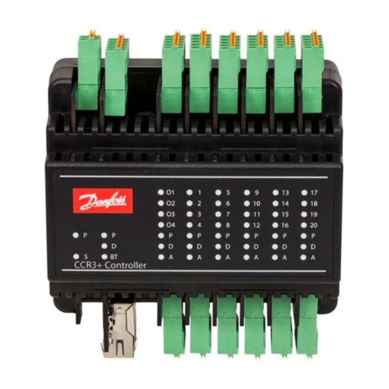
Summary of Contents for Danfoss CCR3+
- Page 1 Operating Guide CCR3+ Controller ENGLISH CCR3+ Controller www.danfoss.com © Danfoss | 2019.02 VI.GM.A2.02 | 1...
- Page 2 CCR3+ Controller Fig. 1 Installation with CCR3+ Controller (up to 20 risers/loops) Fig. 2 Installation with CCR23 Controller (Master) and CCR+ Slave Unit (more that 20 risers) 2 | © Danfoss | 2019.02 VI.GM.A2.02...
- Page 3 G – common ground dedicated to sensors S17-20 C – common port dedicated to actuators V9-12 V9-12 V9..V12 – outputs to actuators C – common port dedicated to actuators V13-16 V13-16 V13..V16 – outputs to actuators VI.GM.A2.02 © Danfoss | 2019.02 | 3...
- Page 4 B2 - Def.input B2 sensor LBus 2x0.5mm2 Type of sensor - PT1000 Type of sensor - PT1000 B3 - Def.input B3 PT1000 (L=max. 100m) Fig. 4 Wiring scheme CCR3+ Master Controller with CCR+ Slave 4 | © Danfoss | 2019.02 VI.GM.A2.02...
- Page 5 G – common ground dedicated to sensors C – common port dedicated to actuators S33-36 S33..S36 – inputs from sensors V33-36 V33..V36 – outputs to actuators G – common ground dedicated to sensors VI.GM.A2.02 © Danfoss | 2019.02 | 5...
-
Page 6: Product Description
Power consumption (Slave Unit only) 3 VA Weight 0.3 kg Installation DIN rail 35 mm To select proper power transformer please follow formula: 24 V 10 VA (controller) + 7 VA*/per each actuator 6 | © Danfoss | 2019.02 VI.GM.A2.02... -
Page 7: Installation
7. Types of Logins and Access Controller has a built in WEB Server App to communicate with all devices with html browsers via following communication interfaces: • Wi-Fi communication port • LAN cable connection (TCP/IP port) VI.GM.A2.02 © Danfoss | 2019.02 | 7... - Page 8 - date list of settings for the given firmware is • Network: BMS and IP/TPC settings • Firmware: Firmware upgrade tool available on the Danfoss website. • Login: Login option New settings can automatically upgrade according to guidelines in instruction. 8 | © Danfoss | 2019.02 VI.GM.A2.02...
-
Page 9: Readings Menu
Required return temperature for measure supply temperature: 63°C TRet(63) Factory setting: 45°C Required return temperature for measure supply temperature: 70°C TRet(70) Factory setting: 48°C Required return temperature for measure supply temperature: 80°C TRet(80) Factory setting: 54°C VI.GM.A2.02 © Danfoss | 2019.02 | 9... - Page 10 Click »Set Settings« to confirm changes. Load settings 1 Load settings from memory 1. Load settings 2 Load settings from memory 2. Save settings 1 Save settings into memory 1. Save settings 2 Save settings from memory 2. 10 | © Danfoss | 2019.02 VI.GM.A2.02...
-
Page 11: Tests Menu
Note: In case of changing IP address in Possible (readable values): 0 – 100% CCR+ Controller, changes should also be Save Settings Click »Save Settings« to confirm changes applied in PC local network settings. VI.GM.A2.02 © Danfoss | 2019.02 | 11... -
Page 12: Firmware Menu
FIRMWARE MENU: 11. CCR3+ DASHBOARD Name Description (Web App Screen) To update CCR3+ with new firmware first download firmware file from Danfoss website. Upgrade of firmware (continuous) Then follow procedure: Browse file -> Start upgrade! Reset settings to default To return all setting to default (except Network settings) click on “Return Defaults”... -
Page 13: Modbus Settings
2. Write single register – data can be written into start addresses: from 300 to 331 - from 400 to 435 3. Write multiple register – data can be written into start addresses: - from 300 to 331 - from 400 to 435 VI.GM.A2.02 © Danfoss | 2019.02 | 13... - Page 14 CCR3+ Controller 14 | © Danfoss | 2019.02 VI.GM.A2.02...
- Page 15 CCR3+ Controller VI.GM.A2.02 © Danfoss | 2019.02 | 15...
- Page 16 CCR3+ Controller VI.GM.A2.02 16 | © Danfoss | DHS-SRMT/SI | 2019.02...


Need help?
Do you have a question about the CCR3+ and is the answer not in the manual?
Questions and answers