Subscribe to Our Youtube Channel
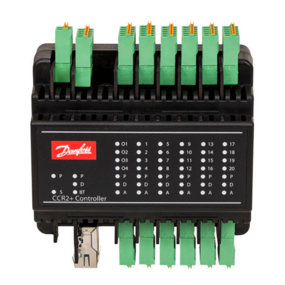
Summary of Contents for Danfoss CCR2+
- Page 1 Operating Guide CCR2+ Controller Master Controller Slave Unit ENGLISH CCR2+ Disinfection Process Control & Temperature Registration www.danfoss.com © Danfoss | 2019.02 VI.D3.C2.02 | 1...
- Page 2 24 VDC 24 VDC Fig. 3a Installation with CCR2+ Controller (Master) and CCR+ Slave Unit (more that 20 risers) ECL... S... V... MTCV MTCV MTCV MTCV MTCV MTCV MTCV MTCV 24 VDC Fig. 3b 2 | © Danfoss | 2019.02 VI.D3.C2.02...
- Page 3 G – common ground dedicated to sensors S13-16 C – common port dedicated to actuators V9-12 S17-20 S17..S20 – inputs from sensors V9-12 V9..V12 – outputs to actuators G – common ground dedicated to sensors S17-20 VI.D3.C2.02 © Danfoss | 2019.02 | 3...
- Page 4 B1 - start dis. S0 - main Risers’ temperature sensors S1...S20 B2 - stop dis. sensor Type of sensor - PT1000 B3 - ext. alarm PT1000 Wiring scheme CCR2+ Master Controller Fig. 4b 4 | © Danfoss | 2019.02 VI.D3.C2.02...
- Page 5 G – common ground dedicated to sensors C – common port dedicated to actuators S33-36 S33..S36 – inputs from sensors V30-36 V33..V36 – outputs to actuators G – common ground dedicated to sensors VI.D3.C2.02 © Danfoss | 2019.02 | 5...
- Page 6 TCP/IP - LAN B1 - start dis. B2 - stop dis. B3 - ext. alarm TEMP S . 0 Fig. 7 Connection of two CCR2+ with individual S0 sensor in sequence mode 20180904 6 | © Danfoss | 2019.02 VI.D3.C2.02...
- Page 7 TCP/IP - LAN B1 - start dis. B2 - stop dis. B3 - ext. alarm TEMP S . 0 Fig. 9 Connection of two CCR2+ with one S0 sensor in parallel mode 20180904 VI.D3.C2.02 © Danfoss | 2019.02 | 7...
-
Page 8: Product Description
To select proper power enclosure are not included. transformer please follow formula: 24 V 10VA (controller) + 7 VA*/per each actuator Example (building with 20 risers): 10VA (for controller) + 7VA x 20 actuators = 150VA 8 | © Danfoss | 2019.02 VI.D3.C2.02... -
Page 9: Types Of Logins And Access
8. Local Network settings (only for LAN cable connection with PC) 1. Go to »Local Network settings« 2. Go to »Properties« -> »Internet Protocol Version 4 (TCP/IPv4) 3. Configure IP address: 4. Confirm with »OK« and close menu in PC. VI.D3.C2.02 © Danfoss | 2019.02 | 9... -
Page 10: Readings Menu
How much data can be stored per day in the system memory (for actually settings) The Real Time clock, show current time, date, day of the week RT Clock Data used in archive file and scheduler. 10 | © Danfoss | 2019.02 VI.D3.C2.02... - Page 11 % of riser disinfection progress Disinfection Count down timer is counting when temp. on riser is higher that Dis.Set.Temp. Time to end [HH:MM] After timer count down to zero, riser is disinfected successfully. VI.D3.C2.02 © Danfoss | 2019.02 | 11...
-
Page 12: Installer Menu
C. This is the signal for CCR2+ to start the disinfection. Parallel function allows the start of the disinfection in all system (all CCR2+ with CCR+ Slave Units in the same time). Main CCR2+ Master revokes the disinfection order for other CCR2+s (with CCR+ Slave Units). Factory setting: Parallel Integration time of the disinfection temperature (and circulation temperature) sustenance process in risers controlled by MTCV valves. - Page 13 For longer cable then 10 meters, used correction factors from table below. Cable Length Cable Usefull tool for calculating cable corrections by selecting cable length (m) and cross (mm Calculator Save settings Click »Save Settings« to confirm changes VI.D3.C2.02 © Danfoss | 2019.02 | 13...
-
Page 14: Scheduler Menu
Password name (can be changed) Factory setting: admin1234 char., max. 15 char.) WIFI connected Shows IP and name of Wi-Fi connected device client Change Login Password name for access to CCR2+ App password: Factory setting: admin1234 14 | © Danfoss | 2019.02 VI.D3.C2.02... -
Page 15: Firmware Menu
Note: In case of changing IP address in CCR+ Controller, changes should also be applied in PC local network settings. FIRMWARE MENU: Name Description To update CCR2+ with new firmware first download firmware file from Danfoss website. Upgrade of firmware Then follow procedure: Browse file -> Start upgrade! Reset settings to default To return all setting to default (except Network settings) click on “Return Defaults”... -
Page 16: Modbus Settings
- from 300 to 303 - from 300 to 303 - from 400 to 421 - from 400 to 421 - from 600 to 620 - from 600 to 620 VI.D3.C2.02 16 | © Danfoss | DHS-SRMT/SI | 2019.02...


Need help?
Do you have a question about the CCR2+ and is the answer not in the manual?
Questions and answers